Introduction
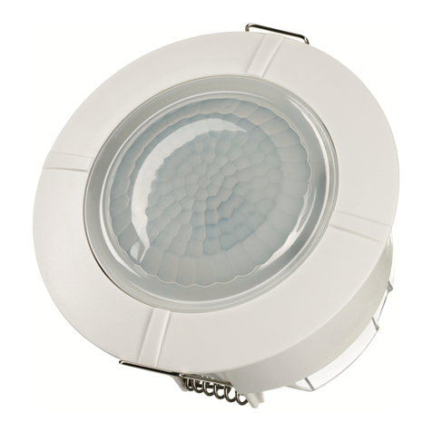
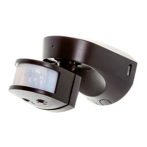
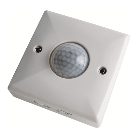
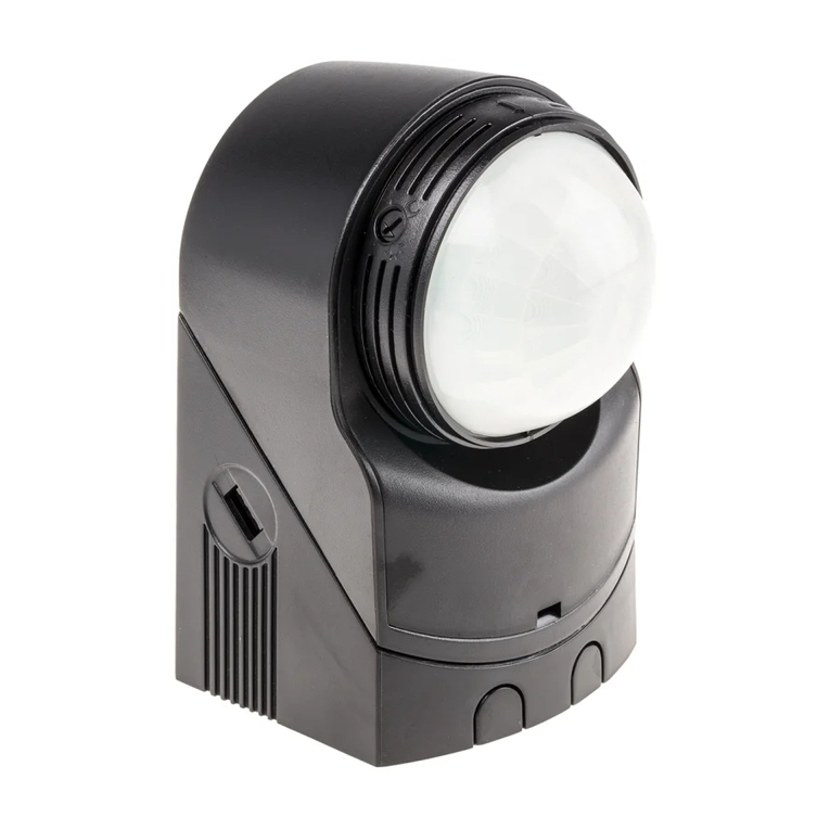
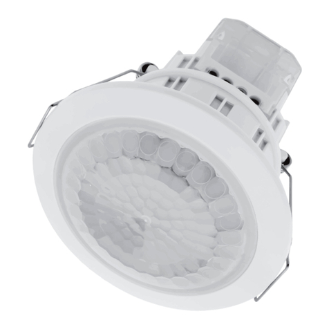
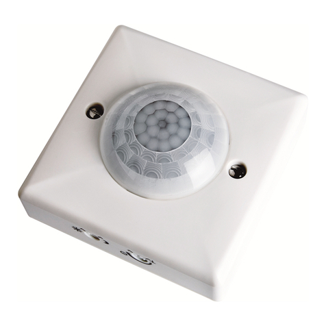
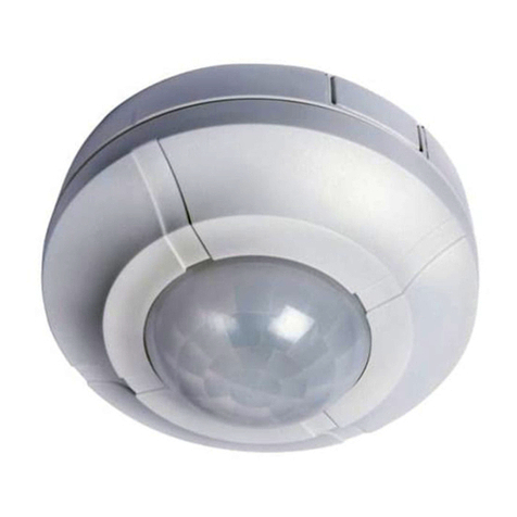
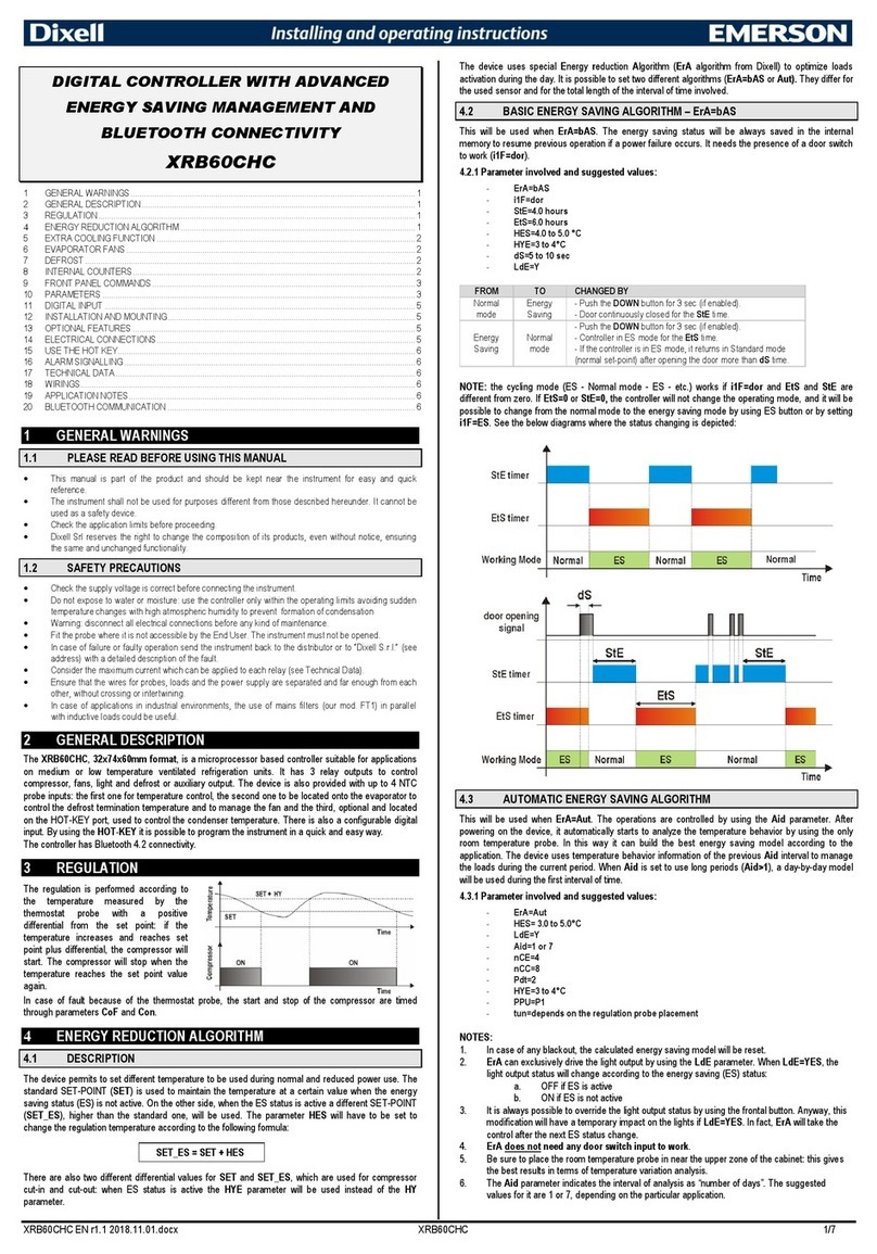
The PDFM1500.1 utilises passive infrared technologyto
detectheatradiationof moving human bodies.Upon
detection,the lightingload will illuminatefor
a user-determinedtime period.An integraldaylight
sensor ensures all day or night-onlyoperation.
ImportantInformation: Light Pollution and
Considerate Lighting
Please be aware of theannoyanceover-lightingan area
can cause to your immediateneighbours.Light
pollutioncaused by incorrectly installing a unit or
over-lightingan area can be limited by carefully
consideringthelocationand positionof your unit
before installation.The light spread on all halogen
floodlightscan be reducedby anglingthefloodlight
downwards on themountingbracket.This will also
concentratethelight on your propertyand limit the
potentialinconvenienceof thelight shining into your
neighbourswindows etc.
Please see Selectinga Location for informationon
choosingtheoptimum locationfor any security light
controlled by this unit.
A
Parts included
•PIR Sensor unit.
•Instruction manual.Please keep safe for future
reference.
•Accessory Pack. Includes cable clampwiring cover
and 2x screws.
Tools and parts needed
•3core flexiblecable.
•Electric/hand-helddrill & bits.
•65mm or 2.5 inch diameterhole r.
•Terminal or Electricians screwdriver.
•Small philips screwdriver.
•Wire
•Suitablemains interconnectcable.
This product is suitablefor indoor use only. Connected
load must notexceedmaximum 2300Whalogen
or 400W fluorescent/lowenergy lighting.
Do not to install if you are suering from
nauseaor dizzy spells or on medicationwith similar
side eects. If in any doubt,consult a qualified
electrician.
Not suitable for use with discharge lighting.
Selectinga location
The motiondetectorhas a numberof detectionzones,
at various vertical and horizontalanglesas shown (see
diagramA).
A moving human body needs to cross/enteroneof
thesezones to activatethesensor. The bestall-round
coverageis achievedwith theunit mountedat the
optimum heightof 3m.
up
Walk Test Procedure
TIME - Fully anti-c lockwise (Test Mode)
DUSK - Fully clockwise
The unit will now operateduring daytime as well as at
night,illuminating thelamp for approx. 5 seconds each
time. This allows testing to be carried out to establis h
whetherthesensor is covering therequired area.
The lamp will immediately illuminate as theunit goes
through its "warm-up" period . Aapproximately 1
minute thelamp will extinguish. Try to remain outside
thedetectionarea during thewarm-up period.
Walk around thesens or to establis h thedetection area.
The sens or will detect within an approximately 9 metr e
diametercircle from the centre of the sensor locationwith a
3m ceiling.
As you cross a detection "zone"thelamp will illuminate.
Now stand still until thelamp extinguishes(this should
take approx. 5 seconds).
Start moving As you cross each
"zone"thelamp will illuminate.
Repeat theabove,walking at various distancesand
angles to theunit. This will help you to confirm the
detection .
B
Side View
Top View
Careful positioningof thesensor will be required to
ensure optimum performance.See diagramA detailing
detectionrangeand direction.
The sensor is more sensitive to movementACROSS its
field of vision thanto movementdirectly TOWARDS
(see diagramB). Therefore positiontheunit so thatthe
sensor looks ACROSS thelikely approach path.
Avoid positioningthesensor where there are any
sources of heatin thedetectionarea (extractorfans,
tumble dryer exhaustsetc.) including oppositeany
otherlight sources such as othersecurity lights.
Reflectivesurfaces (ie pools of wateror white-painted
walls) and overhangingbranchesmay cause false
activationunder extremeconditions.
During extremeweatherconditionsthemotionsensor
may exhibit unusual behaviour . This does notindicate
a faultwith thesens or. Once normal weatherconditions
return,thesensor will resume normal operation.
Connection
Connectthemains supply cable Live core (brown) to L
and Neutral core(Blue) to N terminal.
Connect thelighting cableNeutral core (blue) to N
and Lighting Live core(brown) totheL1 terminal
on theunit as follows (seediagram D):-
NEUTRA L (Blue) N
NEUTRA L (Blue) N
LIVE (Brown) L1
LIVE (Brown) L
Set thetwo adjustment controls on theside of the
unit (diagram C) to the followingpositions:
When wiring is complete, fit the cable clampwiring
cover to the sensor unit with the 2 screws provided.
(diagram E)
TIME -Fully anti-clockwise (Test mode).
DUS K-Fully clockwise.
Push back thelocatingsprings (diagramD) and feed
theunit into theceiling void via the65mm hole.The
locatingsprings will now fold back and hold the
PDFM1500.1 inplace.
Installation
IMPO RTANT
Switch othe electricity at the fuse box by removing the
relevantfuse or switching o
the circuit breaker beforeproceedingwith the installation.
All should be installed by competentperson in
accordance with IEE Wiring Regulations (BS7671)
choosinga suitable location(see previous section)
install theunit as follows:
The unit is suitable for connection to a 230V ac 50Hz
electricity supply. It is suggested that 3-core round
flexible cable of 1.5 sq. mm gauge is used. An isolating
switch should be installed to switch the power to the unit
ON & OFF. This allows the sensor to be easily switched
owhen not required or for maintenancepurposes.
Mark thepositionof the65mm diameterlocatinghole
centre takingcare to avoid ceiling joists and other
obstructions within the65mm diameter. Drill a pilot
hole to takethecentre of thehole r. Use the
hole to cut therequired hole.
Levering area
C
D
Sensor
ECable clamp
Wiring cover
L1 N
Switched
Load
OUT
Mains
Supply
IN
LN
L
ocating
springs
pulled
back
Min 12mm
Max 20mm
3m
3m
Presence detection
Motion detection
9m
360
More
sensitive
Less
sensitive
52 3 4 6
Introduction
The PDFM1500.1 utilises passive infrared technologyto
detectheatradiationof moving human bodies.Upon
detection,the lightingload will illuminatefor
a user-determinedtime period.An integraldaylight
sensor ensures all day or night-onlyoperation.
ImportantInformation: Light Pollution and
Considerate Lighting
Please be aware of theannoyanceover-lightingan area
can cause to your immediateneighbours.Light
pollutioncaused by incorrectly installing a unit or
over-lightingan area can be limited by carefully
consideringthelocationand positionof your unit
before installation.The light spread on all halogen
floodlightscan be reducedby anglingthefloodlight
downwards on themountingbracket.This will also
concentratethelight on your propertyand limit the
potentialinconvenienceof thelight shining into your
neighbourswindows etc.
Please see Selectinga Location for informationon
choosingtheoptimum locationfor any security light
controlled by this unit.
A
Parts included
•PIR Sensor unit.
•Instruction manual.Please keep safe for future
reference.
•Accessory Pack. Includes cable clampwiring cover
and 2x screws.
Tools and parts needed
•3core flexiblecable.
•Electric/hand-helddrill & bits.
•65mm or 2.5 inch diameterhole r.
•Terminal or Electricians screwdriver.
•Small philips screwdriver.
•Wire
•Suitablemains interconnectcable.
This product is suitablefor indoor use only. Connected
load must notexceedmaximum 2300Whalogen
or 400W fluorescent/lowenergy lighting.
Do not to install if you are suering from
nauseaor dizzy spells or on medicationwith similar
side eects. If in any doubt,consult a qualified
electrician.
Not suitable for use with discharge lighting.
Selectinga location
The motiondetectorhas a numberof detectionzones,
at various vertical and horizontalanglesas shown (see
diagramA).
A moving human body needs to cross/enteroneof
thesezones to activatethesensor. The bestall-round
coverageis achievedwith theunit mountedat the
optimum heightof 3m.
up
Walk Test Procedure
TIME - Fully anti-c lockwise (Test Mode)
DUSK - Fully clockwise
The unit will now operateduring daytime as well as at
night,illuminating thelamp for approx. 5 seconds each
time. This allows testing to be carried out to establis h
whetherthesensor is covering therequired area.
The lamp will immediately illuminate as theunit goes
through its "warm-up" period . Aapproximately 1
minute thelamp will extinguish. Try to remain outside
thedetectionarea during thewarm-up period.
Walk around thesens or to establis h thedetection area.
The sens or will detect within an approximately 9 metr e
diametercircle from the centre of the sensor locationwith a
3m ceiling.
As you cross a detection "zone"thelamp will illuminate.
Now stand still until thelamp extinguishes(this should
take approx. 5 seconds).
Start moving As you cross each
"zone"thelamp will illuminate.
Repeat theabove,walking at various distancesand
angles to theunit. This will help you to confirm the
detection .
B
Side View
Top View
Time On Lux
Dusk/Dawn
Careful positioningof thesensor will be required to
ensure optimum performance.See diagramA detailing
detectionrangeand direction.
The sensor is more sensitive to movementACROSS its
field of vision thanto movementdirectly TOWARDS
(see diagramB). Therefore positiontheunit so thatthe
sensor looks ACROSS thelikely approach path.
Avoid positioningthesensor where there are any
sources of heatin thedetectionarea (extractorfans,
tumble dryer exhaustsetc.) including oppositeany
otherlight sources such as othersecurity lights.
Reflectivesurfaces (ie pools of wateror white-painted
walls) and overhangingbranchesmay cause false
activationunder extremeconditions.
During extremeweatherconditionsthemotionsensor
may exhibit unusual behaviour . This does notindicate
a faultwith thesens or. Once normal weatherconditions
return,thesensor will resume normal operation.
Connection
Connectthemains supply cable Live core (brown) to L
and Neutral core(Blue) to N terminal.
Connect thelighting cableNeutral core (blue) to N
and Lighting Live core(brown) totheL1 terminal
on theunit as follows (seediagram D):-
NEUTRA L (Blue) N
NEUTRA L (Blue) N
LIVE (Brown) L1
LIVE (Brown) L
Set thetwo adjustment controls on theside of the
unit (diagram C) to the followingpositions:
When wiring is complete, fit the cable clampwiring
cover to the sensor unit with the 2 screws provided.
(diagram E)
TIME -Fully anti-clockwise (Test mode).
DUS K-Fully clockwise.
Push back thelocatingsprings (diagramD) and feed
theunit into theceiling void via the65mm hole.The
locatingsprings will now fold back and hold the
PDFM1500.1 inplace.
Installation
IMPO RTANT
Switch othe electricity at the fuse box by removing the
relevantfuse or switching o
the circuit breaker beforeproceedingwith the installation.
All should be installed by competentperson in
accordance with IEE Wiring Regulations (BS7671)
choosinga suitable location(see previous section)
install theunit as follows:
The unit is suitable for connection to a 230V ac 50Hz
electricity supply. It is suggested that 3-core round
flexible cable of 1.5 sq. mm gauge is used. An isolating
switch should be installed to switch the power to the unit
ON & OFF. This allows the sensor to be easily switched
owhen not required or for maintenancepurposes.
Mark thepositionof the65mm diameterlocatinghole
centre takingcare to avoid ceiling joists and other
obstructions within the65mm diameter. Drill a pilot
hole to takethecentre of thehole r. Use the
hole to cut therequired hole.
Levering area
C
D
Sensor
ECable clamp
Wiring cover
L1 N
Switched
Load
OUT
Mains
Supply
IN
LN
L
ocating
springs
pulled
back
Min 12mm
Max 20mm
3m
3m
Presence detection
Motion detection
9m
360
More
sensitive
Less
sensitive
52 3 4 6
Locating springs fitted position
Min 12mm
Max 20mm
Time On
setting
Lux
Dusk/Dawn
setting


