manuals.online logo
Brands
  1. Home
  2. •
  3. Brands
  4. •
  5. Elko
  6. •
  7. Controllers
  8. •
  9. Elko iNELS RFGB-20 User manual

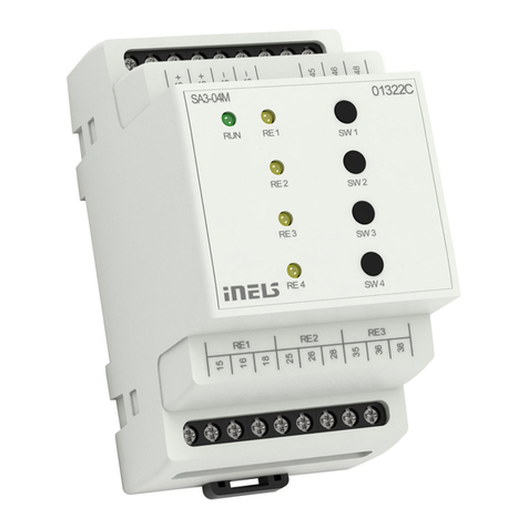
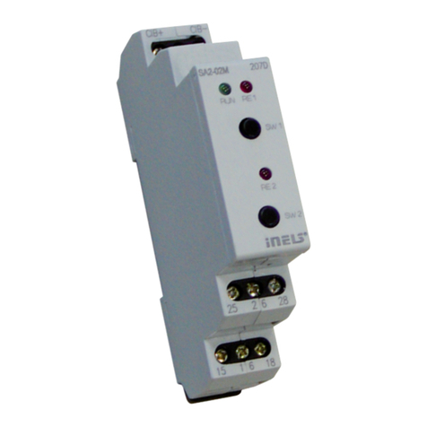
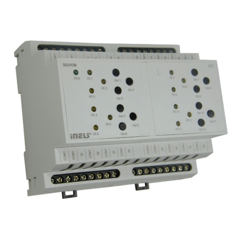
Elko iNELS RFGB-20 User manual

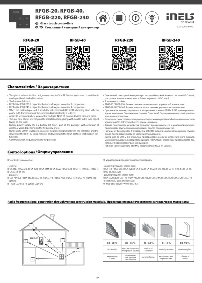
RFGB-20, RFGB-40,
RFGB-220, RFGB-240
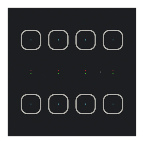
Glass touch controllers
EN
02-01/2021 Rev.0
Characteristics /
RFGB-20 RFGB-40 RFGB-220 RFGB-240
EN
• The glass touch control is a design component of the RF Control system and is available in
an elegant black and white variant.
• Thickness only 8 mm.
• RFGB-20 / RFGB-220: 2 capacitive buttons allow you to control 2 components.
• RFGB-40 / RFGB-240: 4 capacitive buttons allow you to control 4 components.
• When the button is pressed, it sends the set command (ON / OFF, dimming, time off / on,
push/ pull). Transmission of the command is indicated by a red LED.
• Ability to set scenes where you control multiple iNELS RF Control devices with one press.
• The rear base allows screwing on the installation box, gluing with double-sided tape or just
laying on the table.
• Battery power supply (2x 3 V battery CR 2032 - part of the package) with a lifespan of
approx. 2 years depending on the frequency of use.
• Range up to 200 m (outdoors), in case of insufficient signal between the controller and the
device use the RFRP-20 signal repeater or devices with the RFIO2protocol that support this
function.
• Communication frequency with RFIO2protocol.
RF controlers can control:
• switches
RFSA-11B, RFSA-61B, RFSA-62B, RFSA-61M, RFSA-66M, RFSAI-61B, RFSC-11, RFSC-61, RFUS-11,
RFUS-61, RFJA-12B
• dimmers
RFDA-73/RGB, RFDA-11B, RFDA-71B, RFDEL-71B, RFDEL-71M, RFDSC-11, RFDSC-71, RFDAC-71B
• lighting
RF-RGB-LED-550, RF-White-LED-675
Control options /
Radio frequence signal penetration through various construction materials /
x
RFRP-20
60 - 90 % 80 - 95 % 20 - 60 % 0 - 10 % 80- 90 %
brick walls wooden structures
with plaster boards
reinforced
concrete metal partitions common glass
1 /4
• Szklany sterownik dotykowy jest elementem stylistycznym systemu RF Control i jest
dostępny w eleganckiej czerni i bieli.
• Grubość tylko 8 mm.
• RFGB-20 / RFGB-220: 2 przyciski pojemnościowe pozwalają na sterowanie 2 urządzeniami.
• RFGB-40 / RFGB-240: 4 przyciski pojemnościowe pozwalają na sterowanie 4 urządzeniami.
• Po naciśnięciu przycisku nadaje ustawione polecenie (ON/OFF, ściemnianie, czas włączenia/
wyłączenia, wciągnięcie/opuszczenie). Nadanie polecenia sygnalizuje czerwona dioda
LED.
• Możliwość ustawienia scen, w których można sterować większą ilością urządzeń iNELS RF
Control.
• Tylna podstawa umożliwia przymocowanie do puszki instalacyjnej, przyklejenie taśmą
dwustronną lub proste położenie na stole.
• Zasilanie bateriowe (2x 3 V bateria CR2032 – w składzie urządzenia) o żywotności około 2
lat, w zależności od częstotliwości używania.
• Zasięg do 200 m (w wolnej przestrzeni), w przypadku niewystarczającego sygnału
pomiędzy sterownikiem oraz urządzeniem użyj wzmacniacza sygnału (repeatera) RFRP-20
lub urządzenia s protokołem RFIO2, wspierającego tę funkcję.
• Częstotliwość komunikacji z protokołem iNELS RF Control.
Urządzenia RF pozwalają na sterowanie:
• włączniki
RFSA-11B, RFSA-61B, RFSA-62B, RFSA-61M, RFSA-66M, RFSAI-61B, RFSC-11, RFSC-61, RFUS-11,
RFUS-61, RFJA-12B
• ściemniacze
RFDA-73/RGB, RFDA-11B, RFDA-71B, RFDEL-71B, RFDEL-71M, RFDSC-11, RFDSC-71, RFDAC-71B
• oświetlenie
RF-RGB-LED-550, RF-White-LED-675
Charakterystyka
Przenikanie fal radiowych przez różnego rodzaju materiały budowlane
ściana z cegły konstrukcje
drewniane
z płytami gipsowo-
kartonowymi
ściana
żelbetowa
ścianki
metalowe zwykłe szkło
Możliwości sterowania
Szklane sterowniki dotykowe
PL
CR2032
+
CR2032
+
Mounting jig (with brackets) - 1x
Battery*- 2x
* Batteries are inserted in the product. Before
using for the first time, remove the insulating
tape from the battery contacts by pulling in
the direction of the arrow.
Double-sided adhesive label - 4x
Package contents /
Screws- 2x
After inserting the battery, the red LED lights up continuously for 3 seconds and then for 5
seconds, the selected controller function is indicated by flashing LED.
• double flash - standard RFIO2operating mode
• rapid flashing - mode of compatibility with older actuators
If you do not want to change the function of the controller, you must not press any buttons
during this time
To switch between RFIO2mode and compatibility mode:
If you need to change the operating mode of the controller, after inserting the battery, when
the LED is constantly lit. press buttons 1 and 2 simultaneously and hold until the LED starts to
signal the changed mode (double flash or rapid flash). Then the buttons must be released. The
selected function mode is stored in memory and after replacing the battery, the controller
continues to operate in the same mode.
If the controller is used in RFIO2mode, then it is necessary to instruct the controller and link to
the actuators switch to learn mode not only the actuator (according to the instructions for the
actuator), but also the controller in the following way: Remove the battery from the controller,
press some of the buttons several times to discharge the internal capacitors and replace the
battery. When the LED lights up, press button 1 and keep it pressed until the controller starts
signaling the learning mode with short flashing LEDs. Then release the button and the button
now works in RFIO2learning mode. To end the learning mode, remove the battery, press some
of the buttons several times and then replace the battery. Now we do not press any button and
the controller will start again in RFIO2operating mode.
Indicators, settings /
Insertion and replacement of a battery /
1CR2032
+
CR2032
+
2
1
CR2032
CR2032
2
CR2032
3
Press to open the plug-in battery
holder (you can use a flat-blade
screwdriver to open it).
Insert the CR2032 battery into
Battery holder. Watch out for
polarity.
Insert the holder into the device.
or /
CR2032
+
CR2032
+
3
Never mix new and old batteries when replacing! It is always necessary to replace both
batteries at the same time with new ones
2 / 4
Zawartość Paczki
Etykieta dwustronna samoprzylepna - 4x
Urządzenie montażowe
(ze wspornikami) - 1x
Baterie* - 2x
* Baterie założone są w urządzeniu. Przed pier-
wszym użyciem zdejmij taśmę izolacyjną ze
styków baterii, pociągając w kierunku strzałki.
Wkręt - 2x
Po włożeniu baterii przez 3 sekundy świeci czerwona dioda LED, później przez 5 sekund
miganie diody LED sygnalizuje wybraną funkcję sterownika.
• dwukrotne mignięcie – standardowy tryb pracy RFIO2
• szybkie miganie – tryb zgodności ze starszymi aktorami
Jeżeli nie chcesz zmieniać funkcji sterownika, to nie możesz w tym czasie naciskać żadnych
przycisków.
Przełączenie pomiędzy trybem RFIO2i trybem zgodności: Jeżeli zajdzie potrzeba zmiany trybu
pracy sterownika, to po włożeniu baterii, gdy dioda świeci, równocześnie naciśnij przyciski 1 i
2, i przytrzymaj je do momentu, kiedy dioda zacznie sygnalizować zmianę trybu (dwukrotne
mignięcie lub szybkie miganie). Następnie należy zwolnić przyciski. Wybrany tryb funkcji
zostaje zapisany w pamięci, po wymianie baterii sterownik kontynuuje pracę w tym samym
trybie.
Jeżeli sterownik pracuje w trybie RFIO2, to w celu przypisania sterownika do aktorów,
koniecznie należy wprowadzić w tryb nauki nie tylko aktor (zgodnie z instrukcją aktora), ale
również sterownik w następujący sposób: Wyjmij baterię ze sterownika, kilkukrotnie naciśnij
dowolny przycisk, aby rozładować kondensatory wewnętrzne i włóż baterię z powrotem. Gdy
dioda LED się zaświeci, naciśnij przycisk 1 i przytrzymaj go naciśnięty, dopóki sterownik nie
zacznie sygnalizować krótkim miganiem diody LED trybu nauki. Następnie zwolnisz przycisk,
sterownik rozpoczyna pracę w trybie nauki RFIO2. W celu zakończenia trybu nauki, wyjmij
baterię, kilkukrotnie naciśnij dowolny przycisk, następnie załóż z powrotem baterię. Po czym
nie naciskasz żadnych przycisków, sterownik rozpocznie ponownie tryb pracy RFIO2.
Sygnalizacja, ustawienia
Instalacja oraz wymiana baterii
Włóż baterię CR2032 do
uchwytu baterii. Zwróć uwagę
na biegunowość.
Poprzez naciśnięcie otworzysz
zintegrowany uchwyt baterii (możesz
go otworzyć za pomocą płaskiego
śrubokręta).
Wsuń uchwyt do urządzenia.
lub
Nigdy nie kombinuj nowych i starych baterii podczas wymiany! Zawsze konieczna jest wy-
miana obu baterii na nowe.
Technical parameters /
More detailed information can be found in the iNELS RF Control Installation Manual:
https://www.elkoep.com/catalogs-and-brochures
ELKO EP, sro hereby declares that the type of radio equipment RFGB-20, RFGB-40,
RFGB-220, RFGB-240 is in accordance with Directives 2014/53 / EU, 2011/65 / EU,
2015/863 / EU and 2014 / 35 / EU. The full text of the EU Declaration of Conformity is
available on the following websites:
www.elkoep.com/glass-touch-controllers-white-sharp-rfgb-20w
www.elkoep.com/glass-touch-controller---2-buttons-black-sharp-rfgb-20b
www.elkoep.com/glass-touch-controller---4-buttons-white-sharp-rfgb-40w
www.elkoep.com/glass-touch-controller-4-buttons-black-sharp-rfgb-40b
www.elkoep.com/glass-touch-controller---2-buttons-white-round--rfgb-220w
www.elkoep.com/glass-touch-controller---2-buttons-black-round-rfgb-220b
www.elkoep.com/glass-touch-controller---4-buttons-white-round-rfgb-240w
www.elkoep.com/glass-touch-controller---4-buttons-black-round-rfgb-240b
When handling a device unboxed it is important to avoid contact with
liquids. Never place the device on the conductive pads or objects, avoid
unnecessary contact with the components of the device.
Safe handling /
Attention:
When you instal iNELS RF Control system, you have to keep
minimal distance 1 cm between each units. Between the
individual commands must be an interval of at least 1s.
Instruction manual is designated for mounting and also for user of the device. It is always a
part of its packing. Installation and connection can be carried out only by a person with ad-
equate professional qualification upon understanding this instruction manual and functions
of the device, and while observing all valid regulations. Trouble-free function of the device
also depends on transportation, storing and handling. In case you notice any sign of damage,
deformation, malfunction or missing part, do not install this device and return it to its seller.
It is necessary to treat this product and its parts as electronic waste after its lifetime is termi-
nated. Before starting installation, make sure that all wires, connected parts or terminals are
de-energized. While mounting and servicing observe safety regulations, norms, directives and
professional, and export regulations for working with electrical devices. Do not touch parts of
the device that are energized - life threat. Due to transmissivity of RF signal, observe correct
location of RF components in a building where the installation is taking place. RF Control is
designated only for mounting in interiors. The must not be installed into metal switchboards
and into plastic switchboards with metal door - transmissivity of RF signal is then impossible.
RF Control is not recommended for pulleys etc. - radiofrequency signal can be shielded by
an obstruction, interfered, battery of the transceiver can get flat etc. and thus disable remote
control.
Warning /
Power voltage:
Battery life:
Transmission indication:
Number of capacitive buttons:
Communication Protocal:
Frequence:
Signal transmission method:
Range:
Other data
Operating Temprature:
Working Position:
Mounting:
Protection:
Pollution degree:
Dimension:
Weight:
Related standards:
RFGB-20 RFGB-40 RFGB-220 RFGB-240
3 / 4
Dane techniczne
Napięcie zasilania:
Trwałość baterii:
Sygnalizacjanadawania poleceń:
Ilość przycisków:
Protokół komunikacyjny:
Częstotliwość:
Typ transmisjisygnału:
Zasięg:
Pozostałedane
Temperatura robocza:
Pozycjarobocza:
Umocowanie:
Klasa szczelności:
Stopień zanieczyszczenia:
Wymiary:
Waga:
Normy:
Uwaga:
Podczas instalacji systemu iNELS RF Control koniecznym
jest dotrzymanie minimalnej odległości 1 cm pomiędzy
elementami. Wymagany jest odstęp min. 1s pomiędzy
kolejnymi poleceniami.
2x 3 Vbattery CR 2032/ 2x 3 Vbaterie CR 2032
about 2years depending on the frequency of use / 2lata w zależnościod częstotliwości używania
Red LED/ czerwona LED
24 24
RFIO
866–922 MHz
one-way addressed message/ jednokierunkowoskierowane polecenie
in the open up to 200 m/ w wolnej przestrzeni do 200 m
-10 ... +50 °C
any / dowolna
adhesive, screw / przyklejenie, przyśrubowanie
IP20
2
94 x 94 x 8mm 100 x 100 x 8mm
122 g 122 g 122 g 122 g
EN 60669, EN 300 220, EN 301 489 RTTE Directive,NVNo. 426/2000 Coll.(Directive 1999 / EC),
EN 60669, EN 300 220, EN 301 489 dyrektywaRTTE, NVč.426/2000Sb(dyrektywa1999/ES)
Instrukcja obsługi służy do celów montażu oraz dla użytkowników urządzeń. Instrukcja obsługi zawsze
wchodzi w skład opakowania urządzenia. Montaż oraz podłączenie mogą wykonywać wyłącznie osoby z
odpowiednimi kwalifi kacjami zawodowymi, zgodnie z obowiązującymi przepisami, które w odpowiedni
sposób zapoznały się z instrukcją obsługi oraz działaniem urządzeń. Bezproblemowe działanie urządzeń jest
również zależne od wcześniejszego sposobu transportu, magazynowania oraz manipulacji. W przypadku
wykrycia jakichkolwiek oznak uszkodzenia, odkształcenia, awarii lub brakujących elementów, prosimy
o nieinstalowanie urządzenia oraz zwrócenie się do sprzedawcy. Urządzenie lub jego części muszą być
potraktowane po końcu okresu używania jako odpad elektroniczny. Przed rozpoczęciem instalacji należy
upewnić się, że wszystkie przewody, podłączone części lub terminale nie są pod napięciem. W trakcie
montażu lub konserwacji koniecznym jest dotrzymanie przepisów bezpieczeństwa, norm, dyrektyw
oraz przepisów branżowych, dotyczących pracy z urządzeniami elektrycznymi. Nie należy dotykać części
urządzeń pod napięciem - ryzyko zagrożenia życia. Ze względu na właściwe przenikanie fal radiowych RF,
pamiętaj o właściwym umieszczeniu urządzeń w budynku, w którym są instalowane. Urządzenia RF Control
są przeznaczone wyłącznie do montażu wewnątrz budynków. Urządzenia nie mogą być instalowane na
zewnątrz lub w pomieszczeniach wilgotnych, dalej nie mogą być instalowane w metalowych szafach
rozdzielczych lub plastikowych szafach rozdzielczych z metalowymi drzwiami - uniemożliwi prawidłowe
przenikanie fal radiowych. Urządzeń RF Control nie należy używać do sterowania urządzeniami o
podwyższonym ryzyku, takimi jak pompy, el. urządzenia grzewcze bez termostatu, windy, dźwigi, itp.
przepływ fal radiowych może być przerwany, naruszony przez przeszkodę, bateria nadajnika może być
rozładowana itp. Z wyżej wymienionych powodów może dojść do zakłócenia lub uniemożliwienia
sterowania.
Ostrzeżenie
Nie pozwól na kontakt z cieczami w trakcie korzystania z urządzenia bez obudowy. Nie
należy umieszczać urządzenia na powierzchniach przewodnych. Nie dotykaj części
wewnątrz urządzenia.
Bezpieczna manipulacja urządzeniem
1 3
2
Push the brackets out of the
mounting fixture.
Assembly /
Push the holders into the holes.
Free tting /
1 32
Peel off one protective layer on
the doublesided adhesive she-
ets and stick them to the marked
places on the controller.
Peel off the second protective
layer on the double-sided
adhesive sheets and place the
control in the prepared place.
Adhesive /
Depending on the type of sur-
face, clean (remove dust or de-
grease) the place where you
want to place the controller.
13
Place the mounting jig on the
KU box and screw it on.
Screw /
Snap on the controller.
Made in Czech Republic
2
ELKO EP, s.r.o. | Palackého 493 | 769 01 | Holešov, Všetuly | Czech Republic | e-mail: [email protected] | Support: +420 778 427 366
ELKO EP Poland, sp. z o. o. | ul. Motelowa 21 | 43-400 Cieszyn | Polska | e-mail: [email protected] | GSM: +48 785 431 024
Wypchnij wsporniki z uchwytu
montażowego.
Wepchnij uchwyty w otwory.
Montaż
Luźno położone
Zdejmij jedną warstwę
ochronną z dwustronnych
taśm samoprzylepnych i
przyklej je w zaznaczonych
miejscach na sterowniku.
W zależności od rodzaju
powierzchni wyczyść (odpyl lub
odtłuść) miejsce, w którym chcesz
umieścić sterownik.
Zdejmij drugą warstwę
ochronną z dwustronnej taśmy
samoprzylepnej i umieść sterownik
w przygotowanym miejscu.
Umieść przyrząd montażowy
na puszce KU i przykręć.
Przez wkręcanie
Załóż sterownik.
Przez klejenie
www.elkoep.com / www.elkoep.pl
4 /4

This manual suits for next models

6

Other Elko Controllers manuals

Elko iNELS GSB3-40 User manual

Elko

Elko iNELS GSB3-40 User manual

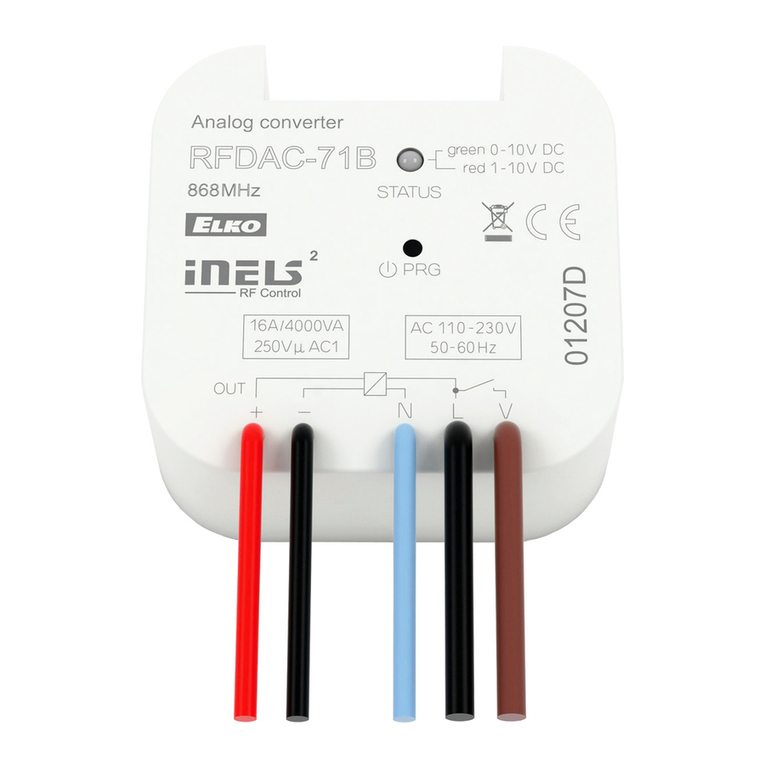
Elko RFDAC-71B User manual

Elko

Elko RFDAC-71B User manual

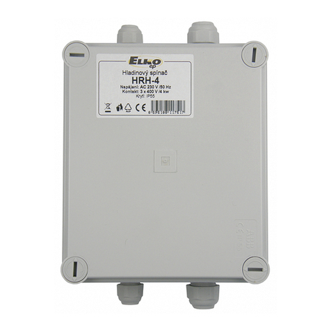
Elko HRH-4 User manual

Elko

Elko HRH-4 User manual

Elko RFWB-20/G User manual

Elko

Elko RFWB-20/G User manual

Elko AirSLC-100L/NEMA User manual

Elko

Elko AirSLC-100L/NEMA User manual

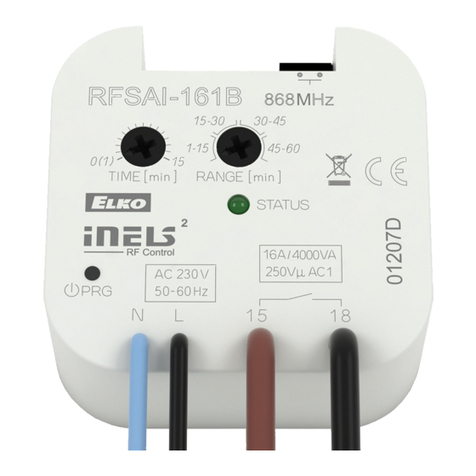
Elko iNels RFSAI-161B User manual

Elko

Elko iNels RFSAI-161B User manual

Elko HRH-4 User manual

Elko

Elko HRH-4 User manual

Elko RFSA-61B User manual

Elko

Elko RFSA-61B User manual

Elko Inels AirSLC-100NB/LWES User manual

Elko

Elko Inels AirSLC-100NB/LWES User manual

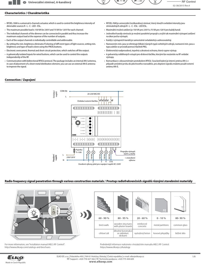
Elko RFDEL-76M User manual

Elko

Elko RFDEL-76M User manual

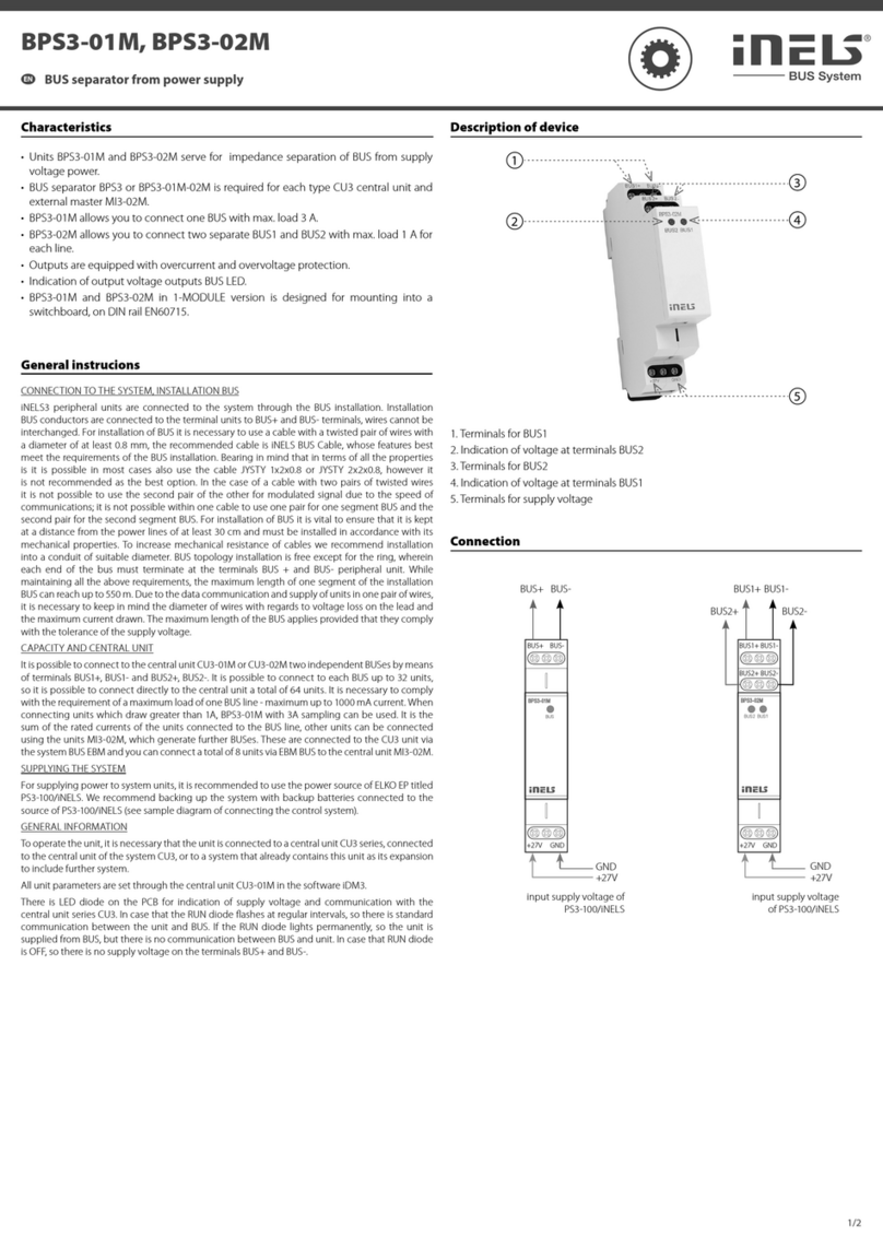
Elko iNels BPS3-01M User manual

Elko

Elko iNels BPS3-01M User manual

Elko inels RFSTI-11B User manual

Elko

Elko inels RFSTI-11B User manual

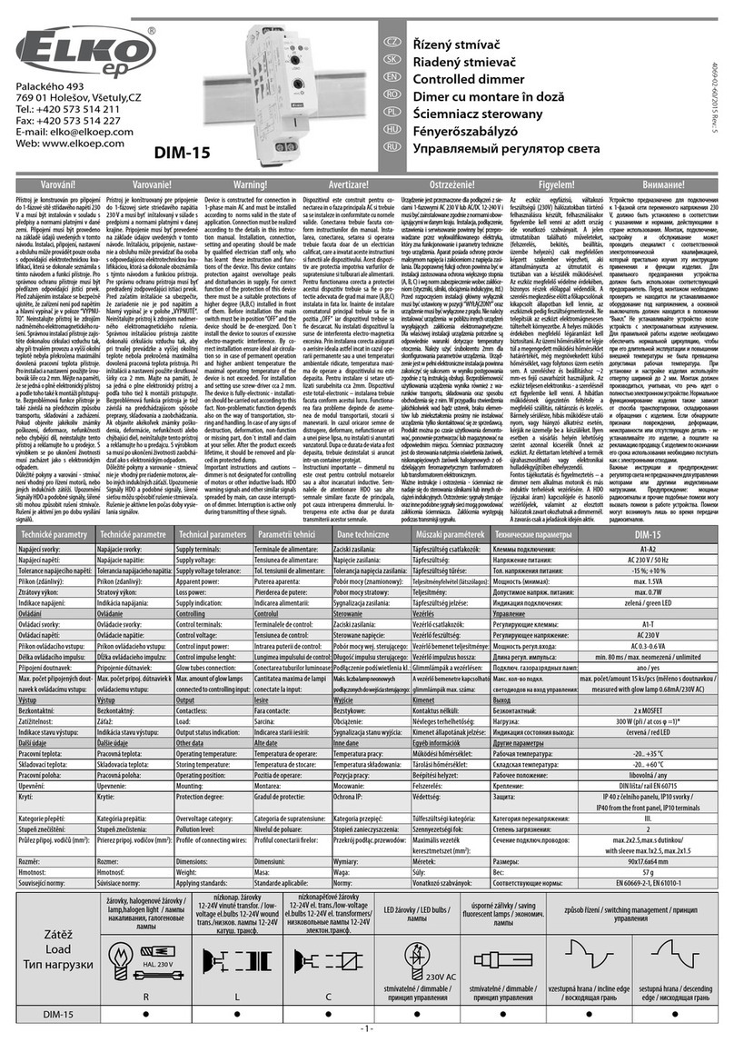
Elko DIM-15 User manual

Elko

Elko DIM-15 User manual

Elko iNELS AirSLC-100NB/NEMA/DALI User manual

Elko

Elko iNELS AirSLC-100NB/NEMA/DALI User manual

Elko iNels SA3-022M User manual

Elko

Elko iNels SA3-022M User manual

Elko RFSA-61B User manual

Elko

Elko RFSA-61B User manual

Elko iNELS AirSLC-100L/LWES Series User manual

Elko

Elko iNELS AirSLC-100L/LWES Series User manual

Elko RFDEL-76M User manual

Elko

Elko RFDEL-76M User manual

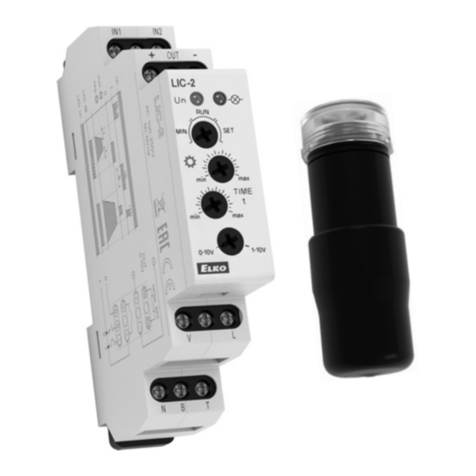
Elko LIC-1 User manual

Elko

Elko LIC-1 User manual

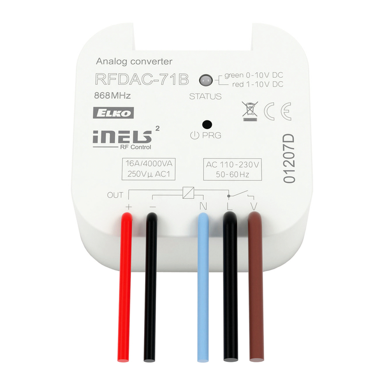
Elko RFDAC-71B User manual

Elko

Elko RFDAC-71B User manual

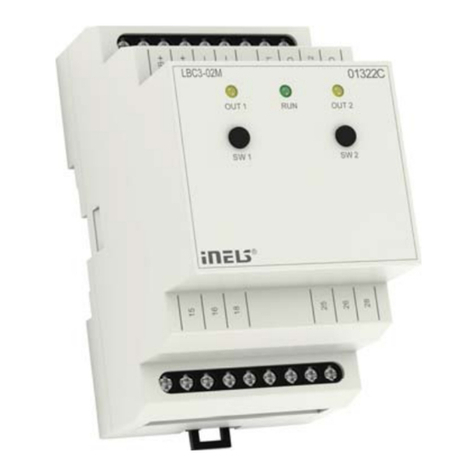
Elko iNels LBC3-02M User manual

Elko

Elko iNels LBC3-02M User manual

Elko iNELS RFGB-20 User manual

Elko

Elko iNELS RFGB-20 User manual

Elko RFWB-20/G User manual

Elko

Elko RFWB-20/G User manual

Elko iNELS Air AirSLC-100 User manual

Elko

Elko iNELS Air AirSLC-100 User manual

Popular Controllers manuals by other brands

Secur ID-11 installation manual

Secur

Secur ID-11 installation manual

Zennio MAXinBOX FANCOIL 4CH2P Technical documentation

Zennio

Zennio MAXinBOX FANCOIL 4CH2P Technical documentation

Mold-Masters TempMaster M1 Plus Series user manual

Mold-Masters

Mold-Masters TempMaster M1 Plus Series user manual

ComAp InteliSys NT troubleshooting manual

ComAp

ComAp InteliSys NT troubleshooting manual

Cielo Perfect Aire PAJS1 manual

Cielo

Cielo Perfect Aire PAJS1 manual

Autogrow IntelliDose Installation and user guide

Autogrow

Autogrow IntelliDose Installation and user guide

USA Technologies VendingMiser VM160 Outdoor Installation Instructions

USA Technologies

USA Technologies VendingMiser VM160 Outdoor Installation Instructions

Alltrax NPX user manual

Alltrax

Alltrax NPX user manual

2VV SC-C quick guide

2VV

2VV SC-C quick guide

Atmel AT91 ARM Thumb Application note

Atmel

Atmel AT91 ARM Thumb Application note

Eaton CDAE-01/04 Installation

Eaton

Eaton CDAE-01/04 Installation

Varian Turbo-V 3KT instruction manual

Varian

Varian Turbo-V 3KT instruction manual

Aqua Environment Inc 211 Owner's operation and maintenance manual

Aqua Environment Inc

Aqua Environment Inc 211 Owner's operation and maintenance manual

ABB RHD250 operating instructions

ABB

ABB RHD250 operating instructions

Niles IRD-8 Quick setup guide

Niles

Niles IRD-8 Quick setup guide

TeeJet 844 Operation manuals

TeeJet

TeeJet 844 Operation manuals

Datakom DKG-379 manual

Datakom

Datakom DKG-379 manual

Controlli MVH56E Mounting instructions

Controlli

Controlli MVH56E Mounting instructions

manuals.online logo
manuals.online logoBrands
  • About & Mission
  • Contact us
  • Privacy Policy
  • Terms and Conditions

Copyright 2025 Manuals.Online. All Rights Reserved.