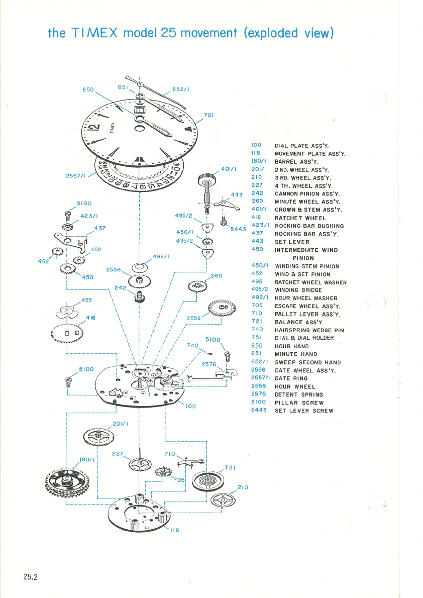
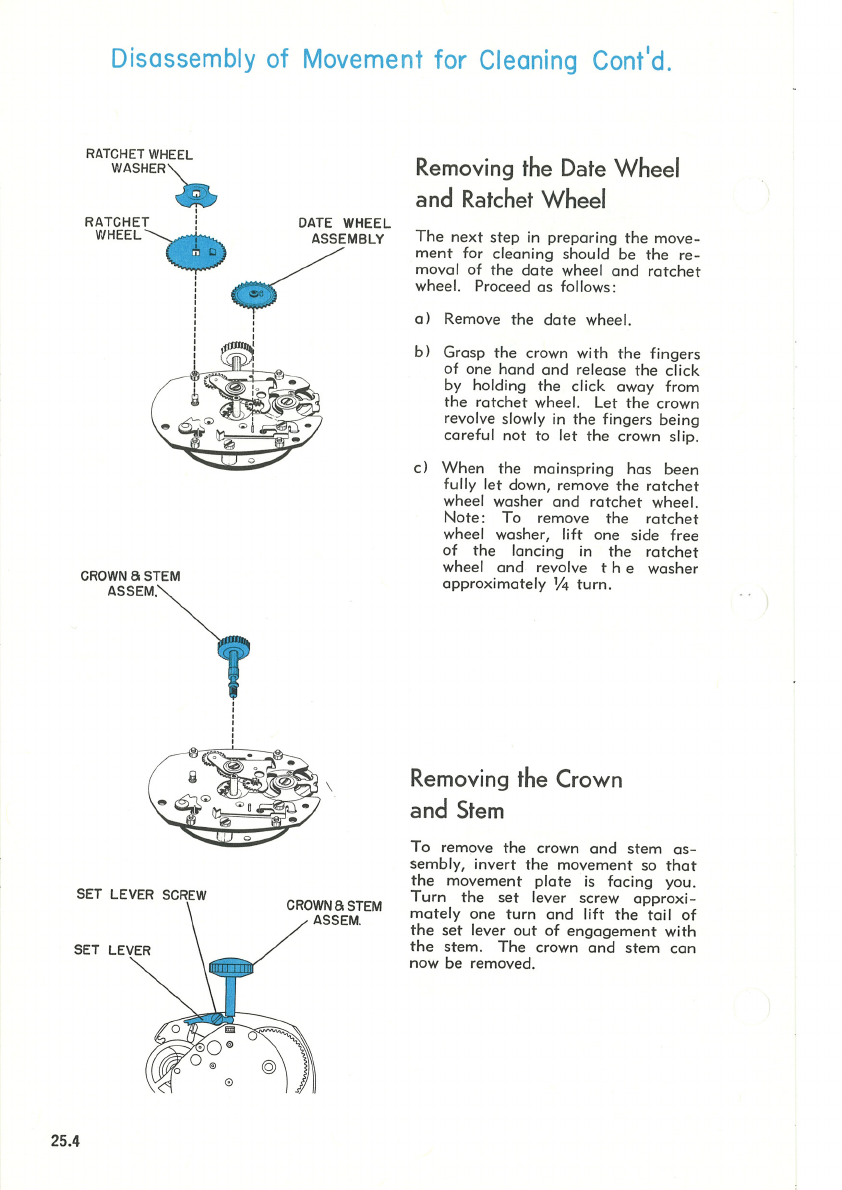
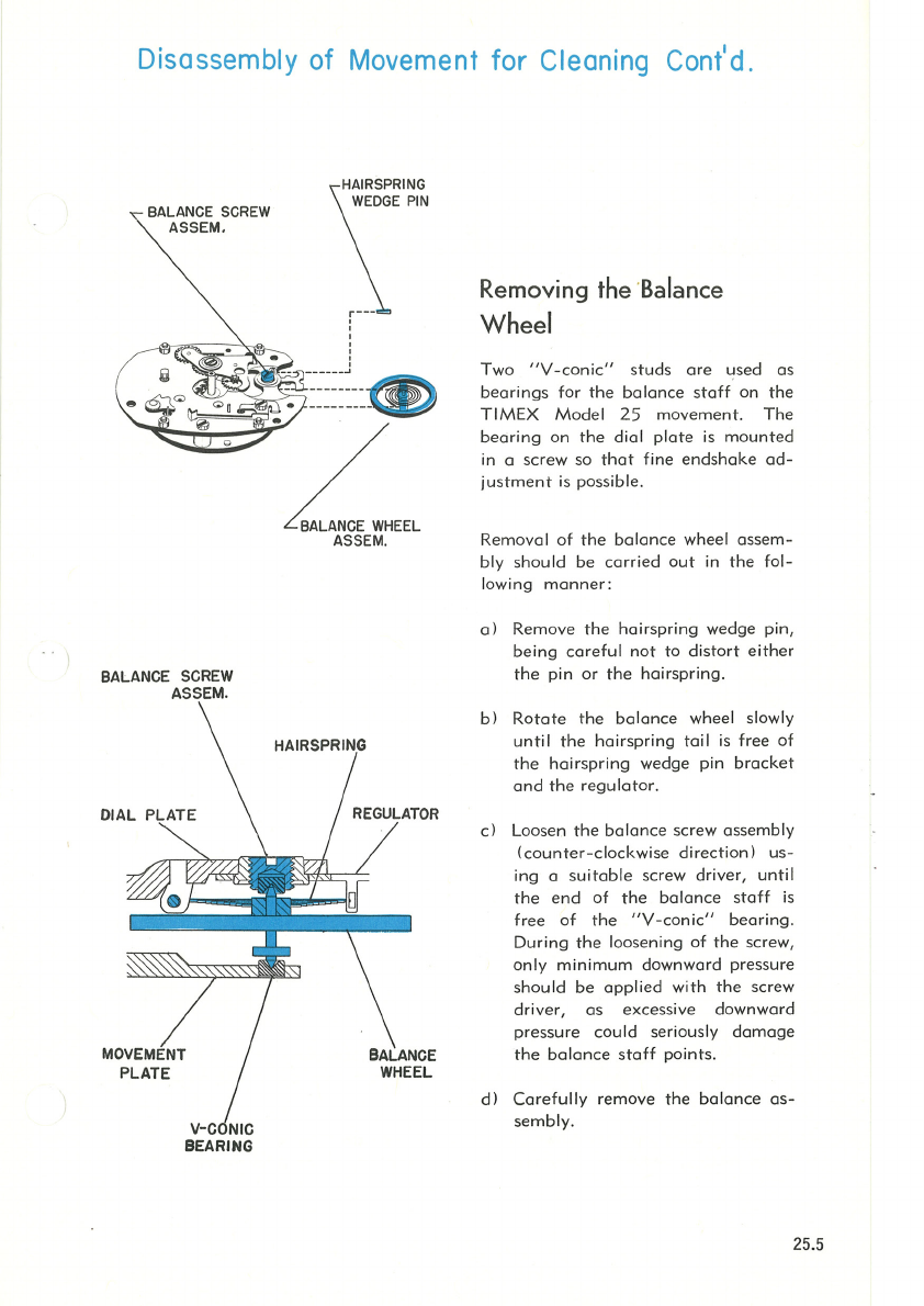
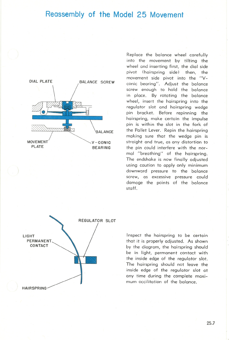
Timex 25 User manual

TIMEX
model 25
calendar watch
9114
by
111,4
lig.
21
.
08
by
25.35
mm
.998
by
.830
in.
(/)
m
JJ
<
s::-
oO
om
~~
N)>
(]1z
c
)>
r

the
TIMEX
Model
25
Movement
The
Timex
Model
25
is
on
11
1
/4
'"
x 9
1;4
"'
calendar
movement
utilizing
the
basic
construction
of
the
Model
24
. Like
the
Model
24
it
features
a
"V-Conic"
Bearing system
and
rugged
two
plate
design.
The
entire
Calendar
mechanism
is
efficiently
housed
between
the
dial
plate
and
dial.
Whereas
most
watches
utilize
bridges, TIMEX
has
constructed
the
Model
25
movement
with full
plates
to
toke
advantage
of
the
accuracy
inherent
in this
type
of design.
This
accuracy
insures
complete
interchangeability
for
the
escape-
ment
and
gear
train
without
the
need
for
selective
fitting
and
adjustments
which
complicate
the
repair
of
most
watches
.
To
clean
the
TIMEX Model
25
it
is
necessary
to remove only
the
sweep
second
hand,
dial,
dote
ring,
dote
wheel
assembly,
ratchet
wheel,
and
balance
.
The
illustrations
on
pages
25.3
through
25.5
show
proper
procedures
. TIMEX
has
found
through
long
and
careful
research
that
the
best
method
of
cleaning
is
with only
the
above
mentioned
ports
removed.
The
cleaning
fluid, while
remov-
ing
any
contamination
from
the
movement
will also remove oil from
the
gear
•rain, pivots
and
holes.
If
further
dismantling
is
required,
removal
of
the
movement
plate
will
expose
the
gear
train
and
associated
ports
.
Re-assembly
should
start
with
the
dial
plate,
exercising normal
core
to
insure
proper
positioning
of
pivots in
their
respective
holes.
The
exploded
view
of
the
movement
on
page
25
.2 will
guide
re-assembly.
Cleaning
and
re-oiling
instructions
for
the
Model
25
movement
ore
given
on
page
25
.
6.
Re-assembly
techniques
ore
shown
on
page
25.7
and
25
.8.
25.1
..

25.2
the
Tl
MEX
model
25
movement
(exploded
view)
495
I /
~
~
416
(
~
~
I
498/ 1
255B
......._
0
242
®
.........
I
I
L
--
--
--
--
----,
r
-
- -
---
-
----
~
1
I I
I 201/1 I
:
~
:
;
~
l
i :
227
'--
$
:
180/1:
_,_,
,.,
) " / I :::;:::)(2
~
m·
·
:
~~
l
___
_
L
----
-
-----
i..
751
5100
740 \
:;::-,
_ '
'
I
__
__
_
___
__
.J
10
0
l i B
100 DIAL PLATE ASS'Y.
118
MOVEMENT
PLATE ASS'Y.
180/1 BARREL ASS'Y.
201
/ 1 2
NO
.
WHEEL
ASS'Y.
210
3
RD.
WHEEL ASS'Y.
227
4TH.
WHEEL ASS'Y.
242
CANNON PINION ASS'Y.
260
MINUTE WHEEL
ASS'Y
.
401/1
CROWN
a
STEM
ASS'Y
.
416 RATCHET
WHEEL
423/1
ROCKING BAR BUSHING
437
ROCKING BAR
ASS'Y
.
443
SET
LEVER
450
INTERMEDIATE
WIND
PINION
450/1
WINDING STEM PINION
452
WIND
a
SET PINION
495
RATCHET WHEEL
WASHER
495
/ 2
WINDING
BRI
DGE
498/1
HOUR
WHEEL WASHER
705
ESCAPE WHEEL ASS'Y.
710
PALLET
LEVER ASS'Y.
721
BALANCE
ASS'Y.
74 0 HAlRSPRING
WEDGE
PIN
751
DIALS
DIAL
HOLDER
850
HOUR HAND
851
MINUTE
HAND
852
/ 1 SWEEP SECOND HAND
2556
DATE WHEEL ASS
'Y
.
2557/1
DATE RING
255B
HOUR
WHEEL
257
6 DETENT SPRING
5100
PILLAR
SCREW
5443
SET
LEVER
SCREW

Disassembly
of
Movement
for
Cleaning
(model
25)
Ml
HAND
DIAL
DIAL
TAB
HOLE
DIAL
HOLDER
DIAL
PLATE
DIAL
HOLE
Removing the dial, date ring
and hands.
a)
Remove
sweep second
hand.
Do
not
remove
the
minute
or
hour
hand.
b)
The
dial
holder,
to
which
the
dial
is
clamped
is
held
on
the
move-
ment
by
means
of
three
tabs
which
are
bent
through
dial
holes,
onto
the
dial
plate.
c)
Once
the
dial
is
off
the
movement,
the
date
ring
can
be
removed.
There
is
no
need
for
further
dis-
assembly
of
the
dial
assembly
for
cleaning
unless severe
contamina-
tion
is
present
on
the
friction
and
cannon
pinions.
Should
further
disassembly
be necess
ary,
removal
of
the
minute
hand
wi
II
free
the
friction
and
cannon
pinion
as-
s
embly.
The
friction
pinion
is
held
in
the
cannon
pinion
by
a
snap
tit.
25.3

Disassembly
of
Movement
for
Cleaning
Cont'd.
RATCHET WHEEL
w
RATCHET
WHEEL
CROWN
SSTEM
ASSEM
l
SET LEVER
SCREW
SET LEVER
25.4
'
'
'
DATE
WHEEL
Removing the Date
Wheel
and
Ratchet
Wheel
ASSEMBLY
The
next
step
in
preparing
the
move-
ment
for
cleaning
should
be
the
re-
\
CROWNS STEM
ASS
EM.
moval of
the
date
wheel
and
ratchet
wheel. Proceed
as
follows :
a)
Remove
the
date
wheel.
b)
Grasp
the
crown with
the
fingers
of
one
hand
and
release
the
click
by holding
the
click
away
from
the
ratchet
wheel. Let
the
crown
revolve slowly
in
the
fingers
being
careful
not
to let
the
crown slip.
c)
When
the
mainspring
has
been
fully let down, remove
the
ratchet
wheel washer
and
ratchet
wheel.
Note
:
Ta
remove
the
ratchet
wheel washer, lift
one
side
free
of
the
lancing
in
the
ratchet
wheel
and
revolve t h e
washer
approximately
V4
turn
.
Removing the Crown
and
Stem
Ta
remove
the
crown
and
stem
as-
sembly, invert
the
movement
sa
that
the
movement
plate
is
facing
you.
Turn
the
set
lever screw
approxi-
mately
one
turn
and
lift
the
tail
of
the
set
lever
out
of
engagement
with
the
stem.
The
crown
and
stem
can
naw
be
removed.

Disassembly
of
Movement
for
Cleaning
Cont'
d.
BALANCE
SCREW
ASSEM.
BALANCE SCREW
~':~
'
'
'
'
'
--------
·
·L,EEL
ASSEM.
Removing the ·Balance
Wheel
Two
"V-conic"
studs
ore
used
as
bearings
for
the
bolance
staff
on
the
TIMEX
Model
25
movement.
The
bearing
on
the
dial
plate
is
mounted
in
a
screw
so
that
fine
endshake
ad-
justment
is possible.
Removal of
the
balance
wheel
assem-
bly
should
be
carried
out
in
the
fol-
lowing
manner:
a)
Remove
the
hairspring
wedge
pin,
being
careful
not
to
distort
either
the
pin
or
the
hairspring.
b)
Rotate
the
balance
wheel slowly
until
the
hairspring
toil
is
free
of
the
hairspring
wedge pin
brocket
and
the
regulator
.
c) Loosen
the
bo
lance
screw
ossemb
ly
(counter-clockwise
direction)
us-
ing a
su
itabl
e screw driver,
until
the
end
of
the
balance
staff
is
free
of
the
"V-conic"
bearing
.
During
the
loosening
of
the
screw,
only
minimum
downward
pressure
should
be
applied
with
the
screw
driver,
as
excessive
downward
pressure
could
seriously
damage
the
balance
staff
points.
d)
Carefully
remove
the
balance
as-
sembly.
25.5

25.6
Cleaning
the
Model
25
Movement
After
removal
of
the
balance
wheel,
and
the
other
ports
mentioned
on
Pages
25.3
through
25.5,
the
movement
is
ready
to
be
cleaned.
If
a
cleaning
machine
is used,
place
the
movement
in
the
basket
with
the
dial
plate
down
to
insure
proper
drainage
of
the
fluid
from
the
mainspring
barrel.
It
should
be
well swirled
in
the
cleaning
fluid
after
which two
sets
of rinsing
fluid
should
be
used.
The
final
cleaning
fluid
must
be
absolutely
clean.
After
cleaning,
the
movement
should
be
thoroughly
dried.
If
a
cleaning
machine
is
not
available,
the
some
procedure
should
be
followed
manually,
by
re-inserting
the
stem
into
the
movement,
grasping
the
movement
firmly
around
the
stem
and
shaking
it
in
the
cleaning
and
rinsing fluids
to
insure
that
the
fluid will
pass
through
the
entire
mechanism.
The
balance
assembly
should
be
cleaned
separately
in a
small
jar
to
prevent
damage
to
the
hairspring.
Only
standard
watch
cleaning
solutions
should
be
used
throughout.
Lubricating
the
Model
25
Movement
The
movement
should
be
re-oiled
in
the
normal
manner
using
only
high
grade
watch
oils (oil
used
in
factory
assembly
is
Elgin
M56b).
The
mainspring
is
permanently
lubricated
with a solid
coating
which
is
not
affected
by
normal
cleaning
solutions
and
should,
therefore,
not
be
oiled.
The
upper
pivot
of
the
escape
wheel
con
be
oiled
through
the
holes in
the
-minute
wheel.
The
"V-conic"
bearings
should
be
oiled
V2
to
%
full
before
replacing
the
balance
wheel.
Oil
both
the
top
and
bottom
sides
of
the
intermediate
wind pinion
and
wind
and
set
pinions.
Oi
I
the
intersection
of
the
rocking
bar
and
set
lever.
A
slot
has
been
provided
at
the
bose
of
the
center
post
to
facilitate
oiling
the
fourth
pinion
upper
pivot.
If
the
friction
pinion
has
been
removed
from
the
cannon
pinion
and
cleaned,
oil
the
friction pinion
before
re-assembly
into
the
cannon
pinion
.
The
impulse pin
should
be
oiled
at
its
working
surface.
Rubber
gaskets
used
on crowns,
such
as
the
type
used
on
waterproof
and
dust-
proof
models,
should
be
lubricated
with silicone
grease
or
silicone oil.

Reassembly
of
the
Model
25
Movement
DIAL PLATE
MOVEMENT
PLATE
LIGHT
PERMANENT
CONTACT
HAIRSPR
BALANCE SCREW
V-CONIC
BEARING
REGULATOR
SLOT
Replace
the
balance
wheel
carefully
into
the
movement
by
tilting
the
wheel
and
inserting
first,
the
dial side
pivot
(hairspring
side)
then,
the
movement
side
pivot
inta
the
"V-
conic
bearing".
Adjust
the
balance
screw
enough
to
hold
the
balance
in
place.
By
rotating
the
balance
wheel,
insert
the
hairspring
into
the
regulator
slot
and
hairspring
wedge
pin
bracket.
Before
repinning
the
hairspring,
make
certain
the
impulse
pin
is
within
the
slat
in
the
fark
of
the
Pallet
Lever. Repin
the
hairspring
making
sure
that
the
wedge
pin is
straight
and
true,
as
any
distortion
ta
the
pin could
interfere
with
the
nor-
mal
"breathing"
of
the
hairspring
.
The
endshake
is
now finally
adjusted
using
caution
to
apply
only
minimum
downward
pressure
to
the
balance
screw,
as
excessive
pressure
could
damage
the
points
of
the
balance
staff.
Inspect
the
hairspring
to
be
certain
that
it
is
properly
adjusted.
As
shown
by
the
diagram,
the
hairspring
should
be
in
light,
permanent
contact
with
the
inside
edge
of
the
regulator
slot
.
The
hairspring
should
not
leave
the
inside
edge
of
the
regulator
slot
at
any
time
during
the
complete
maxi-
mum
occilitation
of
the
balance.
25.7

25.8
Reassembly
of
the
Model
25
Movement
DATE
WHEE
ASSEMBLY
DATE
RING
SWEEP
SECOND
STAFF
INDEXING PIN
SWEEP SECOND HAND
Use
the
following
procedures
in
re-
assembling
the
dote
mechanism
.
a)
Replace
date
wheel
assembly
on
the
movement.
Note:
Dote
wheel
must
be
re-
placed
with Iorge
head
of
bushing
toward
dial
(refer
to
illustrations
on
page
25.4)
b)
Assemble
date
ring
to
the
move-
ment
making
sure
that
the
"Y"
shaped
end
of
the
detent
spring
is
positioned
in
the
space
between
two
teeth
of
the
date
ring.
c)
Rotate
the
dote
wheel
assembly
clockwise so
that
the
indexing
pin
touches
the
exit
side of
the
date
ring
tooth.
d) Position dial
assembly
to
move-
ment
with
hands
set
at
approxi-
mately
2
o'clock.
Then
bend
the
lugs on
the
dial
holder
to
clomp
the
dial
to
movement.
It
is
essen-
tial
that
the
dial
be
clamped
tight
to
the
movement
.
Toke
core
that
the
position of
the
hands,
date
ring
and
date
wheel
assembly
are
not
changed
during
this
operation.
e)
Once
the
dial is
clamped
to
the
movement,
the
action
of
the
date
indexing
can
be
checked.
Index-
ing
should
start
between
the
hours
of
11
and
12. Also,
the
date
ring,
during
the
indexing
and
near
completion
of its
travel,
must
indicate
a
"snapping
effect"
(darts
forward)
of
date
numeral
to
its position in
the
date
window.
If
the
minute
hand
has
been
re-
moved,
replace
it on
the
dial
assembly
·
together
with
the
fric-
tion
and
cannon
pinions
before
the
dial
assembly
is
put
on
the
movement
.
Replace
the
sweep
second
hand
by
driving it
just
below
the
end
of
the
sweep
second
staff
as
shown
in
the
diagram
.
Be
certain
the
sweep
hand
is
set
below
the
chamfer
on
the
top
of
the
staff
.
Other Timex Watch manuals

Timex
Timex 260 User manual

Timex
Timex 100 Lap Ironman Triathlon with the FLIX User manual

Timex
Timex IronMan Run x50+ User manual

Timex
Timex Expedition WS4 User manual

Timex
Timex M921 User manual

Timex
Timex 70 User manual

Timex
Timex W-219 User manual

Timex
Timex M02Q User manual

Timex
Timex W-91 User manual

Timex
Timex W92 User manual

Timex
Timex Run Trainer 2.0 GPS User manual

Timex
Timex W-213 User manual

Timex
Timex M851 User manual

Timex
Timex 896-095000 User manual

Timex
Timex W-184 User manual

Timex
Timex EXPEDITION WORLD TIME DIGITAL User manual

Timex
Timex 52 User manual

Timex
Timex W212 User manual

Timex
Timex UFC KICK DIGITAL User manual

Timex
Timex W-105 User manual