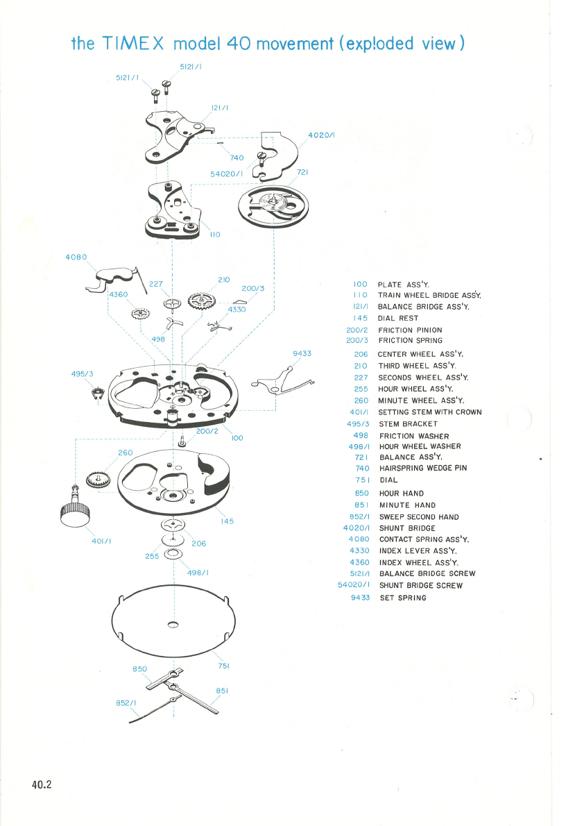
the
TIMEX
Model
40
Movement
The
Timex
Model
40
is
an
9%
x
12%
ligne
electric
watch
movement
.
The
power
to
drive
the
movement
is
supplied
by
a
miniature
energy
cell. Power
from
the
energy
cell drives
the
balance.
The
balance
drives
the
time
train
which,
in
turn,
rotates
the
hands.
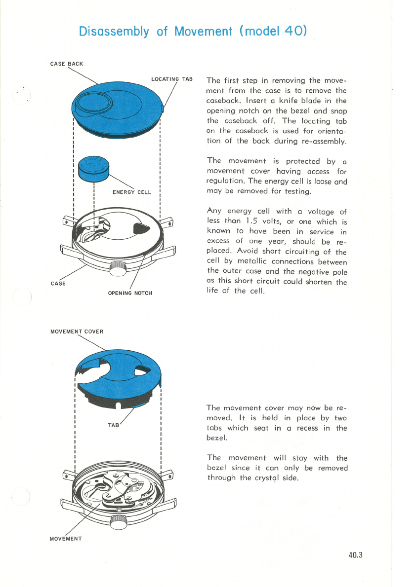
The
energy
cell
is
guaranteed
for
12
months
and
replacement
cells
are
avail-
able
from your local
Timex
dealer,
repair
station
or
the
Timex
Material
Sales
Division.
It
is
important
to
use
only
genuine
Timex
Energy Cells,
Type
A.
Other
types,
although
they
look
the
same,
may
not
deliver
the
necessary
voltage
or
life
and,
in
addition,
may
leak
,
ser
i
ously
damaging
the
movement
.
The
hands
are
set
in
the
normal
method-tha
t is, pulling
out
and
rot
ating
the
crown.
The
Model
40
incorporates
a
device
which
stops
the
movement
when
the
crown
is
in
the
set
position
. In
this
position,
the
flow of
current
from
the
energy
cell
is
interrupted
and
the
energy
cell is
not
being
discharged
.
The
Timex
electric
has
an
hourly
beat
of
21,600
.
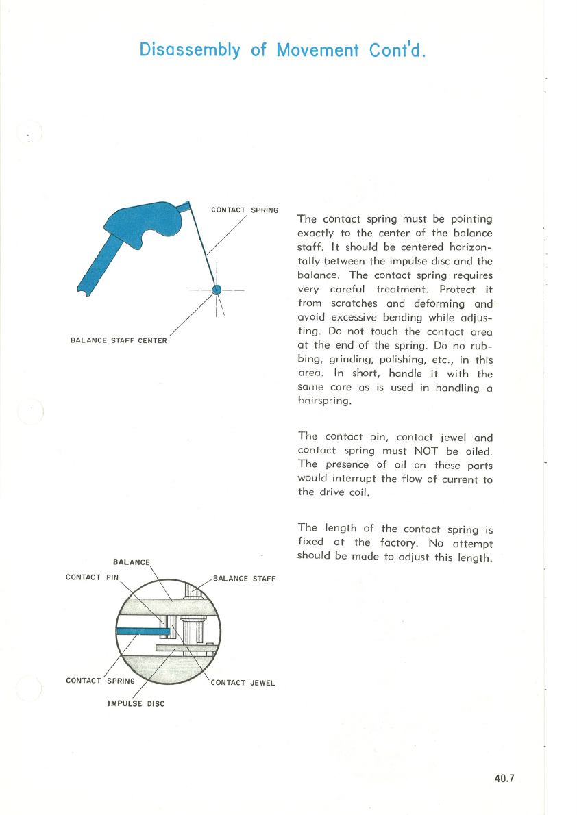
The
large
balance
has
a
temperature
compensated
hairspring
and
the
rate
can
be
adjusted
in
the
usual
way by moving
the
regulator.
The
Timex
electric
can
be
checked
in all positions
on
a
normal
watch
rate
recorder.
The
Timex
electric
can
be
dismantled
and
repaired
with
conventional
tools.
There
is no
need
for special
knowledge
of
electricity
or
electronics,
or
any
need
for
complicated
electrical
measuring
or
inspection
devices, new tools or microscopes.
For
checking
the
battery
voltage,
a
high
ohm
volt
meter
(about
20,000
ohms
per
volt),
which
is
now in
use
in
most
repair
stations,
is
sufficient
.
Since
watch
contains
permanent
magnets,
no
attempt
should
be
made
to
demagnetize
the
watch.
40.1