manuals.online logo
Brands
  1. Home
  2. •
  3. Brands
  4. •
  5. Timken
  6. •
  7. Industrial Equipment
  8. •
  9. Timken ROLLON E-SMART Series User guide

Timken ROLLON E-SMART Series User guide

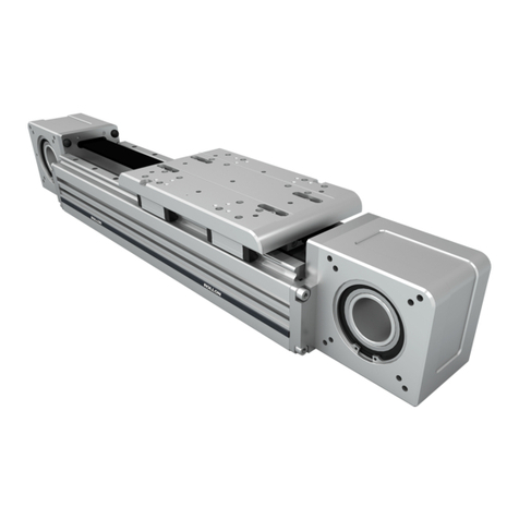
E-SMART
Use and maintenance - Bedienungs- und Wartungsanleitung
BELT DRIVEN LINEAR UNITS
LINEAREINHEITEN MIT RIEMENANTRIEB
Insert the tip of the grease gun in the specific grease blocks.
Repeat this operation every 2000 km or 1 year of use based on the
value reached first.
Type of lubricant: Lithium soap grease of class No. 2.
Quantity of lubricant necessary for re-lubrication for each greaser:
For specially stressed applications or difficult environemental conditions,
lubrication should be carried out more frequently. Apply to ROLLON for
further advice
Die Schmierung erfolgt an den einzelnen Schmiernippeln der Laufwagen.
Das Schmierintervall beträgt 2000 km gefahrener Weg oder eine Be-
triebsdauer von 1 Jahr. Dies ist davon abhängig, welcher Fall zuerst
eintritt.
Zu verwendendes Schmiermittel:
Lithiumseifenfett der Konsistenzklasse 2.
Bei hoher Beanspruchung oder kritischen Umgebungsbedingungen sollte
die Nachschmierung häufiger erfolgen.
Bitte halten Sie hierzu Rücksprache mit unserer Anwendungstechnik.
empfohlene Schmiermittelmenge:
Type/ Typ Quantity [cm3] for greasse nipple
Menge [cm3] pro Schmiernippel
E-SMART 30 1
E-SMART 50 0,2
E-SMART 80 0,5
E-SMART 100 0,6
Lubrication - Schmierung Preliminary operations - Vorbereitende Schritte
1 • Slacken the fixing screws on the upper side of the carriage.
2 • Mark the position of the screws on the tensioning device
and slacken them of the same number of revolutions.
1 • Lösen Sie die Schrauben der Riemenklemmung auf der oberen Seite des
Laufwagens.
2 • Markieren Sie die Position der Schrauben an der Seite der Spanneinheit
und lösen Sie diese jeweils mit der gleichen Anzahl an Umdrehungen.
1
2
Preliminary operations - Vorbereitende Schritte
3 • Remove the fixing screws.
3 • Entfernen Sie die Befestigungsschrauben.
3
WARNING: Perform the same operations on both sides of the carriage. Warnung: Führen Sie die Schritte auf beiden Seiten des Laufwagens aus.
Replacement of the driving belt - Zahnriemenwechsel
4 • Remove the drive belt from both sides of the
carriage and pull off.
To reassemble the belt, carry out the same
operations in the opposite way.
Take particular care to the centering of the belt,
both with regard to the running seat than to the
blocking position of the tensioning device.
4 • Entfernen Sie den Riemen auf beiden Seiten des
Laufwagens und ziehen Sie diesen heraus.
Zur Montage des neuen Zahnriemens führen sie die
vorangegangenen Schritte in umgekehrter Reihenfolge
aus.
Achten Sie auf die exakte Zentrierung des
Zahnriemens. Dieser darf bei einer Bewegung des
Laufwagens in die Endlagen nicht auf einer Seite
anliegen.
4a
4b
Idle removing - Demontage des Umlenkkopfes
FIRST OF ALL CARRY OUT THE OPERATIONS INDICATED AT POINTS 1-2-3
FÜHREN SIE ZUNÄCHST DIE SCHRITTE 1-2-3 AUS
5 • For 80 and 100 version:
For the idle removing unscrew the two screws on
the idle extremity.
6 • For 30 and 50 versions:
For the idle removing is needed to pull off the drive
belt pulley locked in position by a Seeger ring.
7 • End removing by unscrewing the internal screw.
To reassembly the idle, carry out the same
operations in the opposite way.
5 • Für Baugröße 80 und 100:
Lösen und entfernen Sie die Schrauben an der
Stirnseite der Antriebsköpfe.
6 • Für Baugröße 30 und 50:
Zur Demontage des Kopfes muss die Riemenscheibe
entnommen werden. Dazu entfernen Sie zuerst die
Sicherungsringe.
7 • Anschließend lösen und entfernen Sie die
Zentralschraube im Inneren des Kopfes.
Zur Montage der Köpfe führen Sie die Schritte in
umgekehrter Reihenfolge aus.
5
6
7
Sliding block replacement - Ersetzen der Läufer
8 • Remove the fixing screws on the top of the carriage.
9 • Pull off the sliding block.
To reassembly the sliding block, carry out the same
operations in the opposite way.
8 • Entfernen Sie die Befestigungsschrauben an der Oberseite
des Laufwagens
9 • Nehmen Sie die Läufer von der Schiene.
Hinweis: Um den Laufwagen von der Schiene nehmen zu
können, muss mindestens ein Antriebskopf demontiert
werden.
Zur Montage des Laufwagens führen Sie die
vorangegangenen Schritte in umgekehrter Reihenfolge aus.
8
9
Gearbox assembly - Montage eines Planetengetriebes Components / Komponenten
1 Head
2 Pulley unit
3 Transmission belt
4 Profile
5 Ball recirculating linear guide
6 Ball recirculating block
7 Runner
8 Belt tightener
1 Kopf
2 Riemenscheibe mit Lagerung
3 Zahnriemen
4 Aluminiumprofil
5 Linearführungsschiene
6 Linearführungswagen
7 Laufwagen
8 Riemenspanner
- Place the axis as shown in the figure with the gear assembly component facing upwards.
- Assemble the flange on the gear and tighten the screws until the torques shown in Table 1 are reached.
- Place the gearbox complete with flange on the unit without locking it.
- Insert the first spacer from below and then insert the keyless hub without locking it.
- Tighten the gear fixing screws.
- Gradually tighten the keyless hub fixing screws using the cross diagram until the torque shown in Table 2 is reached.
- Loosen and then tighten the gear fixing screws until the torques shown in Table 1 are reached in order for everything
to be correctly set.
Tab. 1 Tab. 2
-Platzieren Sie die Lineareinheit wie in der Abbildung rechts auf einer stabilen Unterlage.
-Montieren Sie den Adapterflansch mit den beiliegenden Befestigungsschrauben an dem Getriebe. (Anzugsmomente siehe Tabelle1)
-Platzieren Sie das Getriebe mit montiertem Flansch auf der Lineareinheit. Beachten Sie dabei, dass die Befestigungsschrauben nicht
angezogen werden.
-Schieben Sie zuerst den Distanzring und dann den Spannsatz auf die Welle, ohne diesen zu verschrauben.
-Ziehen Sie die Befestigungsschrauben am Flansch leicht an
-Ziehen Sie die Schrauben des Spannsatzes in mehreren Schritten und über Kreuz an, bis das erforderliche
Anzugsmonent (siehe Tabelle2) erreicht ist.
-Lösen Sie die Befestigungsschrauben des Flansches und ziehen Sie diese dann mit dem erforderlichen Drehmoment (Tabelle1) an.
Screw 8.8/Schrauben 8.8 Ms in Nm
M2 0.4
M2.5 0.7
M3 1.3
M4 2.8
M5 5.6
M6 9.6
M8 23
M10 46
Shrink ring screw 8.8/Spannsatzschrauben 8.8 Ms in Nm
M2.5 1.2
M3 2.1
M4 4.9
M5 10
M6 17
M8 41
M10 83
1
2
3
4
6
5
8
7
ATTENTION WHEN INSTALLING AND MOVING.
HEAVYEQUIPMENT.
VORSICHT BEI TRANSPORT UND MONTAGE VON SCHWEREN
GEGENSTÄNDEN.
DO NOT OVERLOAD. AVOID TORSIONAL STRESS.
KOMPONENTEN NICHT ÜBERLASTEN ODER VERDREHEN.
AVOID EXPOSURE TO ATMOSPHERIC AGENTS.
VERMEIDEN SIE ES DIE LINEAREINHEIT DER WITTERUNG
AUSZUSETZEN.
IT IS ADVISABLE TO PRE-TEST THE MOTOR BEFORE
CONNECTING AND ASSEMBLING ON THE REDUCTION UNIT.
ES WIRD EMPFOHLEN, DEN MOTOR VOR DER MONTAGE AN
GETRIEBE UND LINEAREINHEIT ZU TESTEN.
AVOID DAMAGE. ALWAYS USE APPROPRIATE TOOLS.
BENUTZEN SIE IMMER GEEIGNETES WERKZEUG UM
BESCHÄDIGUNGEN ZU VERMEIDEN.
PAY ATTENTION TO MOVING PARTS. DO NOT REST
OBJECTS ON THE AXLE.
ACHTEN SIE AUF BEWEGLICHE TEILE. LASSEN SIE KEINE
TEILE AUF DER LINEAREINHEIT LIEGEN.
INSTALLATIONS:CHECK THE DEPTH OF THREADS ON
MOVING PARTS.
PRÜFEN SIE BEI DER MONTAGE DIE GEWINDETIEFE VON
BEWEGLICHEN TEILEN
Warnings - Anmerkungen
FOR FURTHER INFORMATION ABOUT TECHNICAL CHARACTERISTICS, REFER
TO OUR SPECIFIC DOCUMENTATION.
FÜR WEITERE TECHNISCHE DETAILS VERWEISEN WIR AUF UNSERE DETAIL-
LIERTERE (SPEZIFISCHE) DOKUMENTATION.
The Rollon Company shall not be held responsible for damage resulting from incorrect interpretation of these instructions.
The Rollon company reserves the right to modify its products in order to make technical improvements.
Die Rollon GmbH haftet nicht für Schäden, die durch die falsche Interpretation dieser Anleitung entstehen.
Die Rollon GmbH hat das Recht die Produkte, aufgrund von technischen Verbesserungen, zu modifizieren.
Rollon GmbH
Bonner Str. 317-319 - 40589 Düsseldorf
Phone: +49 0211957470 - Fax: +49 021195747100
E-Mail: [email protected] - www.rollon.com
RL_UME-SMART_EN/D_10/18

This manual suits for next models

4

Other Timken Industrial Equipment manuals

Timken ROLLON R-SMART Series User guide

Timken

Timken ROLLON R-SMART Series User guide

Timken Rollon ROBOT User guide

Timken

Timken Rollon ROBOT User guide

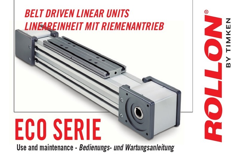
Timken Rollon ECO Series User guide

Timken

Timken Rollon ECO Series User guide

Timken Sheave Pac NP954426-902A1 User manual

Timken

Timken Sheave Pac NP954426-902A1 User manual

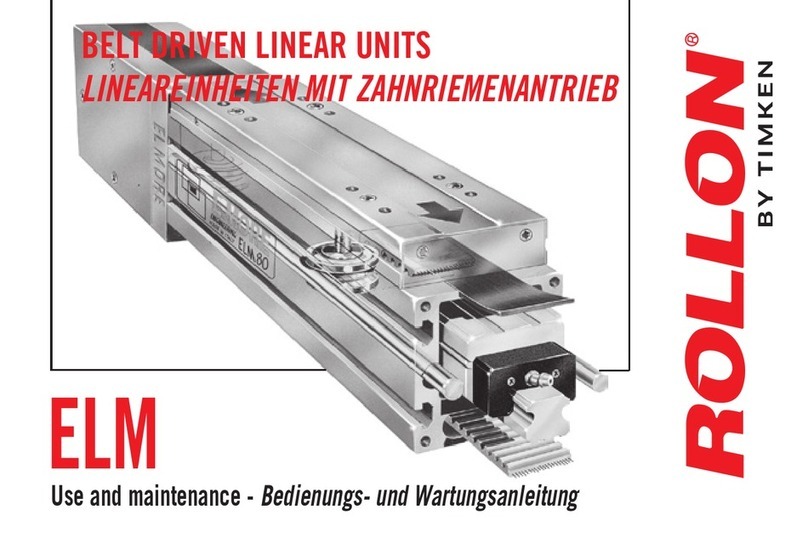
Timken ROLLON ELM Series User guide

Timken

Timken ROLLON ELM Series User guide

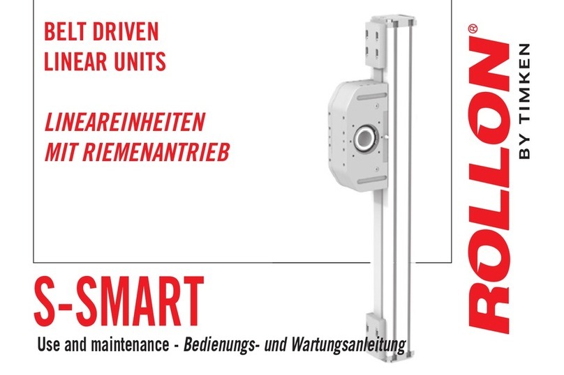
Timken ROLLON S-SMART User guide

Timken

Timken ROLLON S-SMART User guide

Timken ROLLON R-SMART Series User guide

Timken

Timken ROLLON R-SMART Series User guide

Timken Rollon Tecline User guide

Timken

Timken Rollon Tecline User guide

Popular Industrial Equipment manuals by other brands

Axminster PROFESSIONAL AP200SM Original instructions

Axminster

Axminster PROFESSIONAL AP200SM Original instructions

GITRAL VPC Instructions for the user

GITRAL

GITRAL VPC Instructions for the user

ABB HT608464 Operation manual

ABB

ABB HT608464 Operation manual

B&B 3804 Operators safety manual

B&B

B&B 3804 Operators safety manual

Dion PCHM-2 Operation and maintenance instruction

Dion

Dion PCHM-2 Operation and maintenance instruction

Aeroflex S Series instruction manual

Aeroflex

Aeroflex S Series instruction manual

Mototok SPACER 8600 MA Operation manual

Mototok

Mototok SPACER 8600 MA Operation manual

Balluff BTL PA0400 Series Assembly instructions

Balluff

Balluff BTL PA0400 Series Assembly instructions

Reliable B1 Instructions for installation, operation care and maintenance

Reliable

Reliable B1 Instructions for installation, operation care and maintenance

Danfoss DHP-M Commissioning

Danfoss

Danfoss DHP-M Commissioning

schmersal AZM201B-ST2-T-1P2PW-A Instructions for operation

schmersal

schmersal AZM201B-ST2-T-1P2PW-A Instructions for operation

HEIDENHAIN KGM 101 Mounting instructions

HEIDENHAIN

HEIDENHAIN KGM 101 Mounting instructions

Balluff BTL BNC Series installation guide

Balluff

Balluff BTL BNC Series installation guide

Klimawent SCT-2100 Use and maintenance manual

Klimawent

Klimawent SCT-2100 Use and maintenance manual

TRI tool 600RBL-G2 Series Operation manual

TRI tool

TRI tool 600RBL-G2 Series Operation manual

Rondo Econom Series operating manual

Rondo

Rondo Econom Series operating manual

Hoffman PCFF1YZ manual

Hoffman

Hoffman PCFF1YZ manual

Eaton Rapid Link 5 manual

Eaton

Eaton Rapid Link 5 manual

manuals.online logo
manuals.online logoBrands
  • About & Mission
  • Contact us
  • Privacy Policy
  • Terms and Conditions

Copyright 2025 Manuals.Online. All Rights Reserved.