manuals.online logo
Brands
  1. Home
  2. •
  3. Brands
  4. •
  5. Timken
  6. •
  7. Industrial Equipment
  8. •
  9. Timken ROLLON ELM Series User guide

Timken ROLLON ELM Series User guide

ELM UM Ita_IngINTERNAZIONALE:ELM UM Ita_Ing.qxd 26/06/2013 14:37 Pagina 1
ELM
Use and maintenance - Bedienungs- und Wartungsanleitung
BELT DRIVEN LINEAR UNITS
LINEAREINHEITEN MIT ZAHNRIEMENANTRIEB
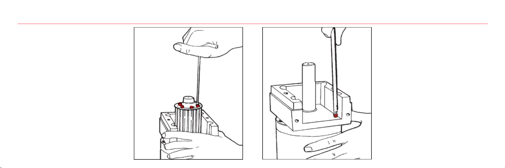
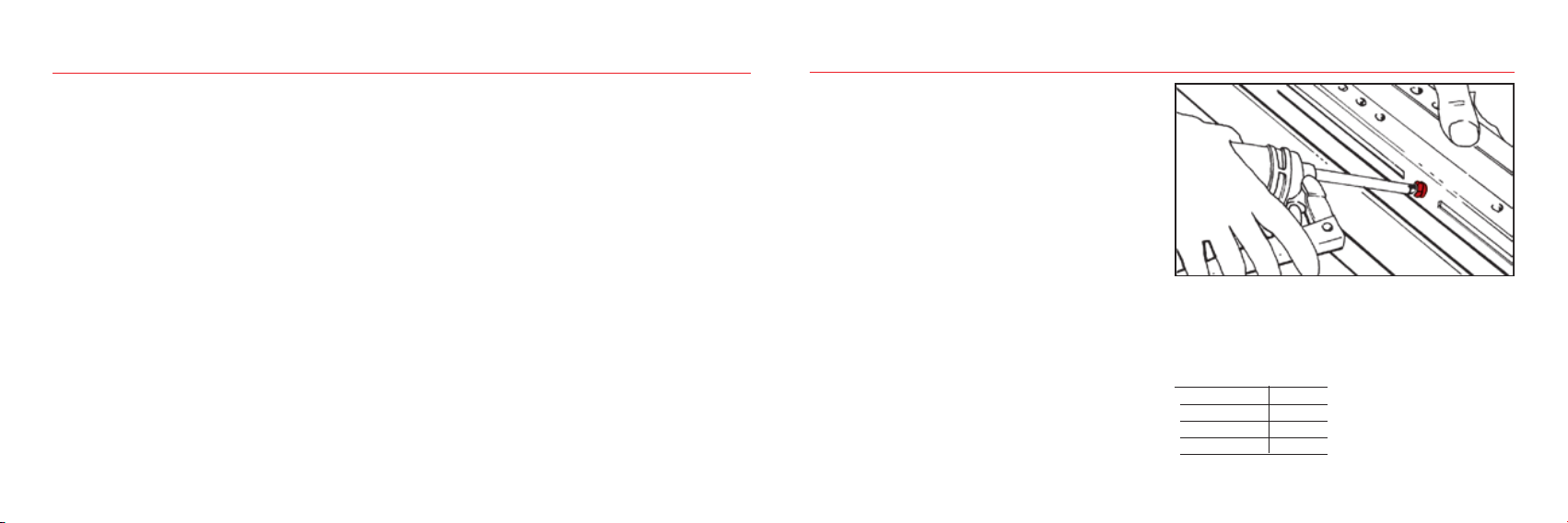
•Insert grease gun into the specific grease nipples.
SP-Type: Repeat this operation every 5000 km or 1 year of use based on the
value reached first.
•Die Schmierung erfolgt an den einzelnen Schmiernippeln.
SP-Version: Das Schmierintervall beträgt 5.000 km gefahrener Weg oder
eine Betriebsdauer von 1 Jahr. Dies ist davon abhängig, welcher Fall zuerst
eintritt.
For lubrication of linear units use lithium soap grease of class No. 2.
Das zu verwendende Schmiermittel ist ein Lithiumseifenfett der
Konsistenzklasse 2.
Lubrication -Schmierung
Unit/Einheit: [cm3]
ELM 50 SP
1
ELM 65 SP
1,4
ELM 80 SP
2,8
ELM 110 SP
4,8
Quantity of lubricant necessary for re-lubrication:
Empfohlene Schmiermittelmenge:
U Manutenzione_UK_DE:ELM UM Ita_Ing.qxd 29/10/2018 22:55 Pagina 3
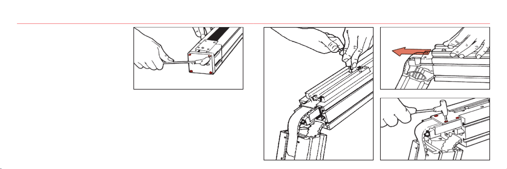
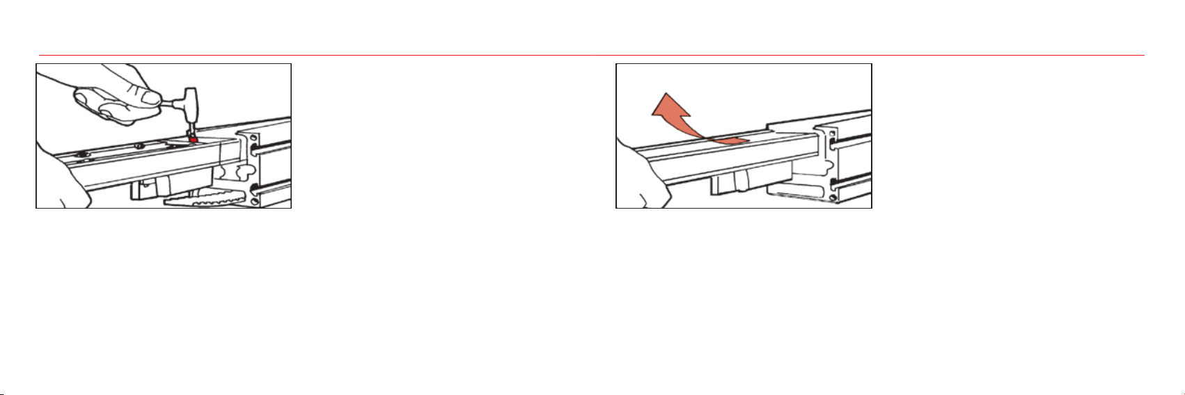
Linear units type SP with linear ball guides
In linear units type SP maintainance-free linear ball guides are used.
On the front plates of the linear blocks special lube-units are mounted
which are continuously providing the necessary quantity of grease to the
ball rows under load.
Linear units type CI with track roller guides
Linear units with track roller guides are equipped with a long period lu-
brication system. Four grease impregnated felt scrapers, complete with
grease reservoirs, guarantee a service life of ca. 6000 km without relu-
brication.
If relubrication is required to obtain a higher service life please con-
tact Rollon.
Lineareinheit Typ SP mit Kugelumlaufführung
In den Lineareinheiten der Ausführung SP werden wartungsarme
Kugelumlauf-Linearführungen eingesetzt. An den Stirnseiten der Line-
arführungswagen sind Schmiervorsätze angebracht, die eine bestimmte
Menge Schmierstoff gespeichert haben und diesen kontinuierlich an die
Kugelumläufe abgeben und so einen wartungsarmen Betrieb ermöglichen.
Lineareinheit Typ CI mit Laufrollenführung
Lineareinheiten mit Laufrollenführungen sind mit einer Langzeitschmierung
ausgestattet. Vier, mit Fett getränkte, Filzabstreifer garantieren eine Ser-
vice Dauer von 6000 km ohne Nachfetten. Wenn eine längere Nachsch-
mierdauer gefordert ist, kontaktieren Sie bitte unsere Anwendungstechnik.
Prior operations - Vorbereitende Arbeitsschritte
1• Lösen Sie die Madenschraube an Position Aund kennzeichnen Sie
die Schrauben der Spannvorrichtung des Antriebriemens.
2• Lösen Sie die Riemenspannschrauben mit 6 vollen Umdrehungen.
3• Lösen und entfernen Sie die seitlichen und stirnseitigen Schrauben
des Antriebskopfes.
4• Entfernen Sie das schwarze U-förmige Blech und anschließend die
dem Antrieb gegenüberliegende Hälfte des Antriebskopfes.
Die andere Hälfte zusammen mit der montierten Zahnriemenscheibe
seitlich aus dem Zahnriemen herausdrehen und herausnehmen.
Für die Montage führen Sie die Schritte in umgekehrter Reihenfolge durch.
1
2
REMOVE THE PROTECTION LABEL FROM THE TAKE-UP SCREWS.
ENTFERNEN SIE DEN SCHUTZAUFKLEBER VON DEN SCHRAUBEN DES UMLENKKOPFES.
AA
1• Slaken the Afixing screws and mark the take-up screws of the belt
tightener.
2• Back off the two screws by 6 turns.
3• Unscrew and remove the side and front screws
of the driving head.
4• Remove the black U-shaped guard and the
half-head opposite the reduction unit.
Slide out the half-block with pulley and reduction unit.
For re-assembly, perform the above operations in reverse order.
U Manutenzione_UK_DE:ELM UM Ita_Ing.qxd 29/10/2018 22:55 Pagina 4
Operations common to each general maintenance phase.
Vorgehensweise für jeden Wartungsschritt
3
4
U Manutenzione_UK_DE:ELM UM Ita_Ing.qxd 29/10/2018 22:55 Pagina 5
5• Loosen and remove the upper screws of the carriage and remove this
checking positioning of the front brushes.
6• Remove the cover of the idle head loosening only the 4 outer screws.
7• Release the belt retention nut.
8• Unscrew the 2 screws of the drive head side and free the belt.
Replace and then re-assemble performing the above operations in reverse
order.
Protection belt replacement - Austausch des Abdeckbandes
5• Lösen und entfernen Sie die oberen Schrauben des Laufwagens und
nehmen Sie ihn ab. Beachten Sie die Position der Bürsten..
6• Entfernen Sie die Abdeckung des Umlenkkopfes, indem Sie die vier
Schrauben lösen.
7• Lösen Sie die Abdeckriemenbefestigungsschraube.
8• Lösen Sie die zwei Schrauben an der Stirnseite des Antriebs und
lösen Sie den Abdeckriemen.
5
6
U Manutenzione_UK_DE:ELM UM Ita_Ing.qxd 29/10/2018 22:55 Pagina 6
First of all carry out the operations indicated at points 1- 2 - 3 - 4
Führen Sie zuerst die Schritte 1 - 2 - 3 - 4 aus
7
8
U Manutenzione_UK_DE:ELM UM Ita_Ing.qxd 29/10/2018 22:55 Pagina 7
Drive belt replacement - Zahnriemenwechsel
9• Unscrew the 4 screws of the idle head and remove this. To facilitate
this operation, traverse the carriage manually at the same time.
10 • Remove the T-shaped part.
11 • Partially extract the carriage.
12 • Remove belt tightener plate A.
13 • Fully extract the carriage and remove the rear belt tightener plate B.
Replace the belt.
For re-assembly, repeat the above operations in reverse order.
9• Lösen Sie die vier Schrauben des Umlenkopfes an der Seite und
entfernen Sie diesen. Bewegen Sie den Laufwagen manuell, um dies
zu erleichtern..
10 • Demontieren Sie das T-förmige Bauteil.
11 • Schieben Sie den Laufwagen zum Teil aus der Lineareinheit raus.
12 • Entfernen Sie die Riemenklemmung A
13 • Entfernen Sie nun den ganzen Laufwagen. Lösen und entfernen Sie
die Riemenklemmunge B.
Ersetzen Sie den Zahnriemen.
Für die Montage die Schritte in umgekehrter Reihenfolge durchführen.
9
U Manutenzione_UK_DE:ELM UM Ita_Ing.qxd 29/10/2018 22:55 Pagina 8
First of all carry out the operations indicated at points 1 - 2 - 3 - 4 - 5 - 6
Führen Sie zuerst die Schritte 1 - 2 - 3 - 4 - 5 - 6 aus
A
1 0
1 1
1 2
U Manutenzione_UK_DE:ELM UM Ita_Ing.qxd 29/10/2018 22:55 Pagina 9
14 • Release the carriage from the guides and replace
the bearings or sliding blocks.
During re-assembly, particular attention must be paid
to alignment and mechanical tolerances
14 • Entfernen Sie den Laufwagen von der Schiene und ersetzen Sie den
Laufwagen.
Beachten Sie bitte bei der Montage die Ausrichtungen sowie mechanische
Toleranzen.
Replacement of bearings or ball re-circulation
sl
B
1 3
U Manutenzione_UK_DE:ELM UM Ita_Ing.qxd 29/10/2018 22:55 Pagina 10
n s
liding blocks - Austausch des Laufwagen der Rollen- oder Kugelumlaufführung
1 4
FIRST OF ALL CARRY OUT THE OPERATIONS
INDICATED UNTIL HERE
FÜHREN SIE ZUERST DIE SCHRITTE AUS, DIE BIS HIERHIN
ERLÄUTERTWORDEN SIND.
U Manutenzione_UK_DE:ELM UM Ita_Ing.qxd 29/10/2018 22:55 Pagina 11
15 • Loosen the screws of the tapered spline of the drive pulley TAKING
CARE to mark their position on the shaft of the reduction unit.
16 • Slide out the pulley.
Remove the screws fastening the reduction unit to the drive
half-head.
Separate the parts.
15 • Lösen Sie die Schrauben des Spannsatzes der Riemenscheibe.
Achten Sie darauf die Position auf der Welle des
Getriebes zu markieren.
16 • Entnehmen Sie die Riemenscheibe.
Entfernen Sie die Schrauben, die das Getriebe am
Antriebskopf befestigen.
Separieren Sie die verschiedenen Teile.
Reduction unit side replacement or change - Austausch des Getriebes
1 5
U Manutenzione_UK_DE:ELM UM Ita_Ing.qxd 29/10/2018 22:55 Pagina 12
FIRST OF ALL CARRY OUT THE OPERATIONS
INDICATED AT POINTS 1 - 2 - 3 - 4
BITTE FÜHREN SIE ZUERST DIE ZUVOR GENANNTEN
SCHRITTE 1 - 2- 3 - 4 AUS.
REDUCTION UNIT SIDE REPLACEMENT OR CHANGEOVER MUST BE
CARRIED OUT VERY CAREFULLY IN ORDER TO GUARANTEE PERFECT
FUNCTIONING OF THE SYSTEM.
THE ELMORE COMPANY SHALL NOT BE HELD RESPONSIBLE FOR
INCORRECT RE-ASSEMBLY OF THE PARTS CONCERNED.
EIN EINWANDFREI FUNKTIONIERENDES SYSTEM KANN NUR
GEWÄHRLEISTET WERDEN, WENN DER AUSTAUSCH DES GETRIEBES
GEWISSENHAFT ERFOLGT.
DIE ROLLON GMBH HAFTET NICHT FÜR SCHÄDEN, DIE DURCH
FALSCHE (DE-) MONTAGE DER BETROFFENEN BAUTEILE,
ENTSTANDEN SIND.
5
1 6
U Manutenzione_UK_DE:ELM UM Ita_Ing.qxd 29/10/2018 22:55 Pagina 13
ELM SP Linear unit - Components Lineareinheit ELM SP - Komponenten
1 Anodised aluminium extrusion
2 Driving head
3 Driving pulley
4 Idle pulley with tensioning unit
5 Linear guide rail
6 Driving belt
7 Protection belt
8 Grease nipple
9 Brush-seal holder
10 Carriage
11 Linear guide block
1 Eloxiertes Aluminiumprofil
2 Antriebskopf
3 Antriebsriemenscheibe mit Spannsatz
4 Umlenkscheibe mit Spanneinheit
5 Schiene der Kugelumlaufführung
6 Zahnriemen
7 Abdeckband
8 Schmiervorsatz
9 Bürstenhalterung
10 Laufwagen
11 Linearführungswagen
U Manutenzione_UK_DE:ELM UM Ita_Ing.qxd 29/10/2018 22:55 Pagina 14
ELM CI Linear unit - Components Lineareinheit ELM CI - Komponenten
1 Anodised aluminium extrusion
2 Driving head
3 Driving pulley
4 Idle pulley with tensioning unit
5 Ball bearing guides
6 Driving belt
7 Protection belt
8 Greaser
9 Brush holder
10 Carriage
11 Gothic arch bearing
1 Eloxiertes Aluminiumprofil
2 Antriebskopf
3 Antriebsscheibe mit Spannsatz
4 Umlenkscheibe mit Spanneinheit
5 Geschliffene Stahl Rundstäbe
(CI verwendet Laufrollen, keine
Kugelumlaufführung)
6 Zahnriemen
7 Abdeckband
8 Schmierfilz
9 Bürstenhalterung
10 Laufwagen
11 Gotische Laufrolle
U Manutenzione_UK_DE:ELM UM Ita_Ing.qxd 29/10/2018 22:55 Pagina 15
RL_UMELM_UK/DE_10/18
ATTENTION WHEN INSTALLING AND MOVING.
HEAVYEQUIPMENT.
VORSICHT BEI TRANSPORT UND MONTAGE VON SCHWEREN
GEGENSTÄNDEN.
DO NOT OVERLOAD. AVOID TORSIONAL STRESS.
KOMPONENTEN NICHT ÜBERLASTEN ODER VERDREHEN.
AVOID EXPOSURE TO ATMOSPHERIC AGENTS.
VERMEIDEN SIE ES DIE LINEAREINHEIT DER WITTERUNG
AUSZUSETZEN.
IT IS ADVISABLE TO PRE-TEST THE MOTOR BEFORE
CONNECTING AND ASSEMBLING ON THE REDUCTION UNIT.
ES WIRD EMPFOHLEN, DEN MOTOR VOR DER MONTAGE AN
GETRIEBE UND LINEAREINHEIT ZU TESTEN.
AVOID DAMAGE. ALWAYS USE APPROPRIATE TOOLS.
BENUTZEN SIE IMMER GEEIGNETES WERKZEUG UM
BESCHÄDIGUNGEN ZU VERMEIDEN.
PAY ATTENTION TO MOVING PARTS. DO NOT REST
OBJECTS ON THE AXLE.
ACHTEN SIE AUF BEWEGLICHE TEILE. LASSEN SIE KEINE
TEILE AUF DER LINEAREINHEIT LIEGEN.
INSTALLATIONS:CHECK THE DEPTH OF THREADS ON
MOVING PARTS.
PRÜFEN SIE BEI DER MONTAGE DIE GEWINDETIEFE VON
BEWEGLICHEN TEILEN
Warnings - Anmerkungen
FOR FURTHER INFORMATION ABOUT TECHNICAL CHARACTERISTICS, REFER
TO OUR SPECIFIC DOCUMENTATION.
FÜR WEITERE TECHNISCHE DETAILS VERWEISEN WIR AUF UNSERE DETAIL-
LIERTERE (SPEZIFISCHE) DOKUMENTATION.
The Rollon Company shall not be held responsible for damage resulting from incorrect interpretation of these instructions.
The Rollon company reserves the right to modify its products in order to make technical improvements.
Die Rollon GmbH haftet nicht für Schäden, die durch die falsche Interpretation dieser Anleitung entstehen.
Die Rollon GmbH hat das Recht die Produkte, aufgrund von technischen Verbesserungen, zu modifizieren.
Rollon GmbH
Bonner Str. 317-319 - 40589 Düsseldorf
Phone: +49 0211957470 - Fax: +49 021195747100
E-Mail: [email protected] - www.rollon.com

This manual suits for next models

4

Other Timken Industrial Equipment manuals

Timken Sheave Pac NP954426-902A1 User manual

Timken

Timken Sheave Pac NP954426-902A1 User manual

Timken ROLLON R-SMART Series User guide

Timken

Timken ROLLON R-SMART Series User guide

Timken Rollon ROBOT User guide

Timken

Timken Rollon ROBOT User guide

Timken Rollon Tecline User guide

Timken

Timken Rollon Tecline User guide

Timken ROLLON R-SMART Series User guide

Timken

Timken ROLLON R-SMART Series User guide

Timken Rollon ECO Series User guide

Timken

Timken Rollon ECO Series User guide

Timken ROLLON S-SMART User guide

Timken

Timken ROLLON S-SMART User guide

Timken ROLLON E-SMART Series User guide

Timken

Timken ROLLON E-SMART Series User guide

Popular Industrial Equipment manuals by other brands

Axminster PROFESSIONAL AP200SM Original instructions

Axminster

Axminster PROFESSIONAL AP200SM Original instructions

GITRAL VPC Instructions for the user

GITRAL

GITRAL VPC Instructions for the user

ABB HT608464 Operation manual

ABB

ABB HT608464 Operation manual

B&B 3804 Operators safety manual

B&B

B&B 3804 Operators safety manual

Dion PCHM-2 Operation and maintenance instruction

Dion

Dion PCHM-2 Operation and maintenance instruction

Aeroflex S Series instruction manual

Aeroflex

Aeroflex S Series instruction manual

Mototok SPACER 8600 MA Operation manual

Mototok

Mototok SPACER 8600 MA Operation manual

Balluff BTL PA0400 Series Assembly instructions

Balluff

Balluff BTL PA0400 Series Assembly instructions

Reliable B1 Instructions for installation, operation care and maintenance

Reliable

Reliable B1 Instructions for installation, operation care and maintenance

Danfoss DHP-M Commissioning

Danfoss

Danfoss DHP-M Commissioning

schmersal AZM201B-ST2-T-1P2PW-A Instructions for operation

schmersal

schmersal AZM201B-ST2-T-1P2PW-A Instructions for operation

HEIDENHAIN KGM 101 Mounting instructions

HEIDENHAIN

HEIDENHAIN KGM 101 Mounting instructions

Balluff BTL BNC Series installation guide

Balluff

Balluff BTL BNC Series installation guide

Klimawent SCT-2100 Use and maintenance manual

Klimawent

Klimawent SCT-2100 Use and maintenance manual

TRI tool 600RBL-G2 Series Operation manual

TRI tool

TRI tool 600RBL-G2 Series Operation manual

Rondo Econom Series operating manual

Rondo

Rondo Econom Series operating manual

Hoffman PCFF1YZ manual

Hoffman

Hoffman PCFF1YZ manual

Eaton Rapid Link 5 manual

Eaton

Eaton Rapid Link 5 manual

manuals.online logo
manuals.online logoBrands
  • About & Mission
  • Contact us
  • Privacy Policy
  • Terms and Conditions

Copyright 2025 Manuals.Online. All Rights Reserved.