manuals.online logo
Brands
  1. Home
  2. •
  3. Brands
  4. •
  5. Timken
  6. •
  7. Industrial Equipment
  8. •
  9. Timken Rollon ECO Series User guide

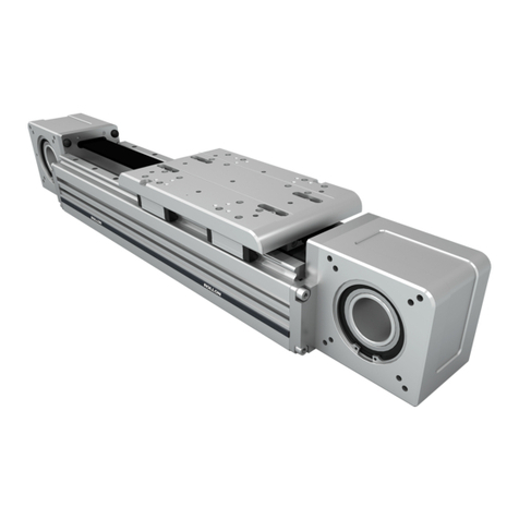
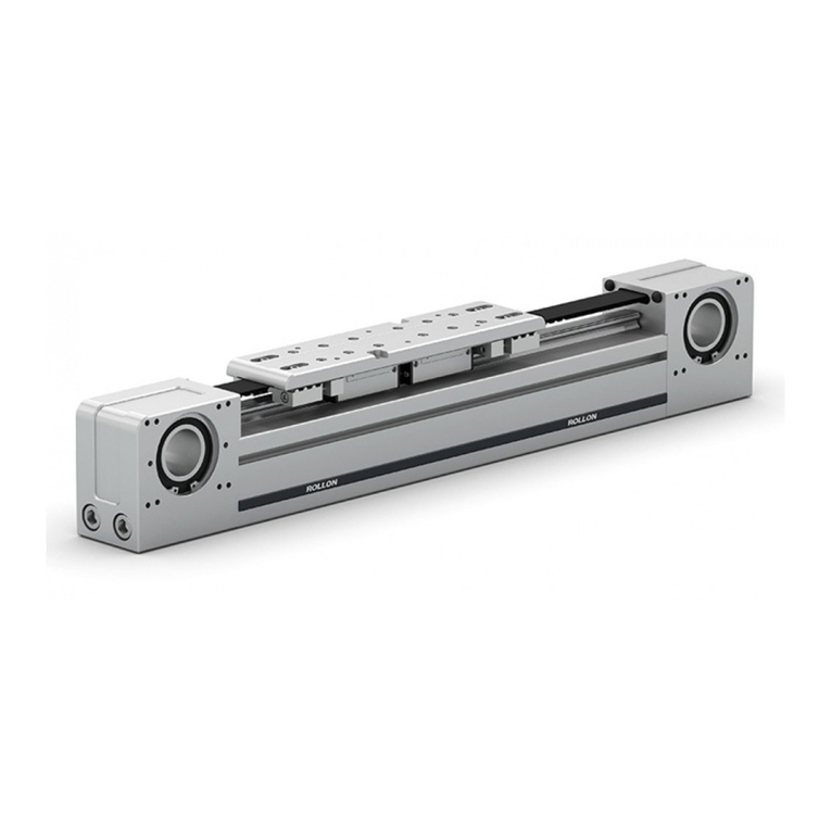
Timken Rollon ECO Series User guide

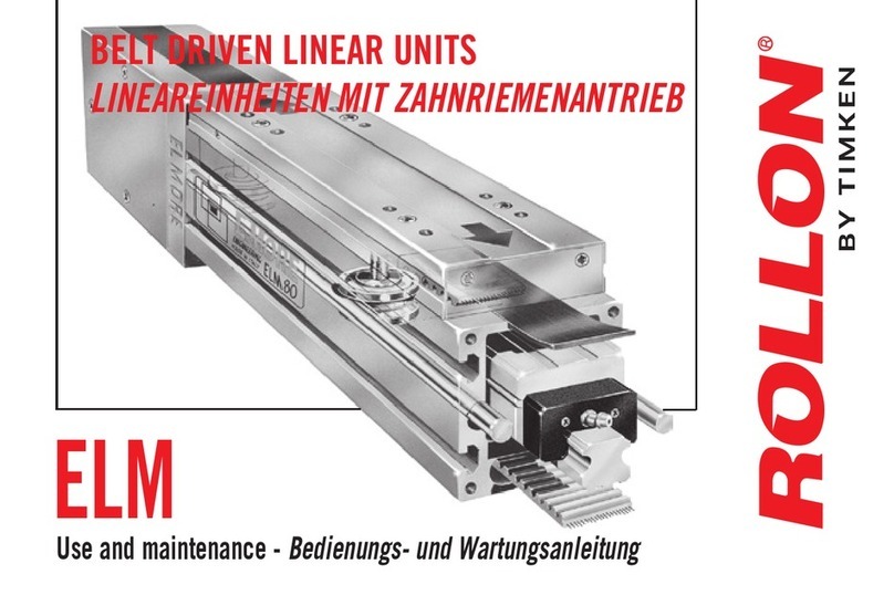
BELT DRIVEN LINEAR UNITS
LINEAREINHEIT MIT RIEMENANTRIEB
ECO SERIE
Use and maintenance - Bedienungs- und Wartungsanleitung
• Insert grease gun into the specific grease nipples.
SP-Type: Repeat this operation every 5000 km or 1 year of use based on the
value reached first.
• Die Schmierung der Führungswagen erfolgt über die Schmieröffnungen im
Aluminiumprofil. Schmieren Sie jeden Führungswagen über die jeweiligen Sch-
miernippel. Das Schmierintervall beträgt 5000Km gefahrener Weg oder eine
Betriebsdauer von 1 Jahr.
For lubrication of linear units use lithium soap grease of class No. 2.
Verwenden Sie zur Nachschmierung Lithiumseifenfett der Klasse NLGI2.
Quantity of lubricant necessary for re-lubrication:
Empfohlene Schmiermenge pro Laufwagen:
Lubrication - Schmierung
Unit/Einheit: [cm3]
ECO 60 1
ECO 80 1,4
ECO 100 2,8
OPERATIONS COMMON TO EACH GENERAL MAINTENANCE PHASE.
VORGEHENSWEISE FÜR JEDEN WARTUNGSSCHRITT.
1 • Unscrew and take off the fixing screws of the protection cover
on both extremities of the axle.
2 • Remove both covers carrying out the operation as indicated in
the drawing.
3 • Slacken the tightening screws of the tensioning device on the
idler extremity.
4 • Mark the position of the tensioning device, then slacken it for
about two revolutions.
1• Lösen Sie die Schrauben des Antriebs- und Umlenkkopfes.
2• Die Blenden durch leichtes Abkippen entfernen.
3• Lösen Sie die Sicherungsschrauben der Spannvorrichtung am
Umlenkkopf.
4• Markieren Sie sich die Position der Zahnriemenklemmung,
lösen Sie anschließend die Schrauben der Klemmung mit zwei
Umdrehungen.
Preliminary operations - Vorbereitende Schritte zur Demontage
1
2 3 4
FIRST OF ALL CARRY OUT THE OPERATIONS INDICATED AT POINTS 1-2-3-4
FÜHREN SIE VORHER DIE SCHRITTE 1-2-3-4 AUS
5 • Unscrew and remove the idle end fixing screws.Remove the two
lateral elements.
6 • Pull of the pulley.
7 • Move the carriage toward the extremity of the axle free from the
idler end and make it protrude outward. Turn upside down the
axle and then remove the fixing screws of the forward tensioning
device, than the rearward one.
8 • To reassemble the belt, carry out the same operations in the
opposite way.
Take particular care to the centering of the belt,both with
regard to the running seat than to theblocking position of
the tensioning device.
5• Lösen und entfernen Sie die seitlichen Schrauben des Umlenkkopfes.
Entfernen Sie anschließend beide Lagerplatten.
6• Entfernen Sie die Zahnriemenscheibe.
7• Ziehen Sie den gesamten Laufwagen aus dem Aluminiumprofil und
lösen Sie die Zahnriemenklemmung auf der unterseite des Linea-
reinheit. Drehen Sie dazu die gesamte Lineareinheit auf den Kopf.
8• Zur Montage der Einheit führen Sie die vorausgegangenen Schritte
in umgekehrter Reihenfolge aus.
Legen Sie beim Zusammenbau besonderen Wert auf die
Zentrierung des Zahnriemens am Laufwagen, sowie in der
Spannvorrichtung.
Replacement of the driving belt - Zahnriemenwechsel
5 7
86
FIRST OF ALL CARRY OUT THE OPERATIONS INDICATED AT POINTS 1-2-3-4-5-6-7
FÜHREN SIE VORHER DIE SCHRITTE 1-2-3-4-5-6-7 AUS
9 • Remove the M4 shoe fixing screws unscrewing them, with a key,
from the upper side.
Remove the shoe to be replaced.
10 • Insert the new shoe in its seat, blocking it, without tightening,
with the M4 shoes.
Insert the aligning rail.
11 • Using a flat support surface, press the aligning rail to bring
the shoe to adhere perfectly to the seat built on the bottom of
the carriage.
Tighten the M4 screws in progression.
9• Lösen und entfernen Sie die Schrauben auf der Oberseite des
Laufwagens.
Entfernen Sie die Führungswagen im Anschluss.
10 • Schrauben Sie die neuen Führungswagen an den Laufwagen
ohne die Schrauben fest anzuziehen.
Führen Sie den Laufwagen auf die Führungsschiene, sodass
sich die Führungswagen ausrichten können.
11 • Richten Sie den Laufwagen entsprechend der Referenzkante
aus. Diese befindet sich auf der Laufwagenunterseite.
Ziehen Sie die Schrauben nach erfolgter Ausrichtung fest.
Shoe replacement - Führungswagenwechsel
9 11
10
REPLACEMENT OR CHANGE OF SIDE OF THE GEAR REDUCTION BOX
GETRIEBEAUSTAUSCH/ ANTRIEBSSEITENWECHSEL
12 • Slacken and remove the screws of the fixing flange. Take out the
gear reduction bow
For changing the side or for the replacement, it is sufficient to position
the gear reduction box on the desired side and block it progressively with
its screws
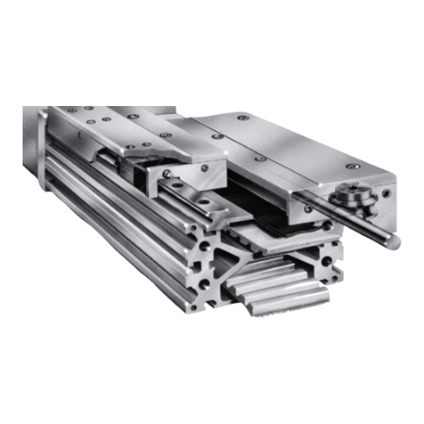
1 Anodized aluminum profile
2 Driving end
3 Hollow shaft driving pulley
4 Idle pulley with tensioning device
5 Ball recirculating linear guide
6 Driving belt
7 Idle end
8 Ball recirculating block
9 Carriage
1 Aluminiumprofil
2 Antriebskopf
3 Zahnriemenscheibe mit Hohlwelle
4 Umlenkscheibe mit Spannvorrichtung
5 Führungsschiene
6 Zahnriemen
7 Umlenkkopf
8 Führungswagen
9 Laufwagen
12 • Lösen und entfernen Sie die Schrauben des Flansches und
entnehmen Sie das Getriebe.
Bei einem Getriebe- oder Antriebsseitenwechsel ist auf eine exakte
Ausrichtung und Befestigung des Flansches und Getriebes wertzulegen.
ECO linear units - Components / Komponenten
1
7
4
6
5
8
9
6
6
3
2
12
RL_UMECO_UK/DE_10/18
ATTENTION WHEN INSTALLING AND MOVING.
HEAVYEQUIPMENT.
VORSICHT BEI TRANSPORT UND MONTAGE VON SCHWEREN
GEGENSTÄNDEN.
DO NOT OVERLOAD. AVOID TORSIONAL STRESS.
KOMPONENTEN NICHT ÜBERLASTEN ODER VERDREHEN.
AVOID EXPOSURE TO ATMOSPHERIC AGENTS.
VERMEIDEN SIE ES DIE LINEAREINHEIT DER WITTERUNG
AUSZUSETZEN.
IT IS ADVISABLE TO PRE-TEST THE MOTOR BEFORE
CONNECTING AND ASSEMBLING ON THE REDUCTION UNIT.
ES WIRD EMPFOHLEN, DEN MOTOR VOR DER MONTAGE AN
GETRIEBE UND LINEAREINHEIT ZU TESTEN.
AVOID DAMAGE. ALWAYS USE APPROPRIATE TOOLS.
BENUTZEN SIE IMMER GEEIGNETES WERKZEUG UM
BESCHÄDIGUNGEN ZU VERMEIDEN.
PAY ATTENTION TO MOVING PARTS. DO NOT REST
OBJECTS ON THE AXLE.
ACHTEN SIE AUF BEWEGLICHE TEILE. LASSEN SIE KEINE
TEILE AUF DER LINEAREINHEIT LIEGEN.
INSTALLATIONS:CHECK THE DEPTH OF THREADS ON
MOVING PARTS.
PRÜFEN SIE BEI DER MONTAGE DIE GEWINDETIEFE VON
BEWEGLICHEN TEILEN
Warnings - Anmerkungen
FOR FURTHER INFORMATION ABOUT TECHNICAL CHARACTERISTICS, REFER
TO OUR SPECIFIC DOCUMENTATION.
FÜR WEITERE TECHNISCHE DETAILS VERWEISEN WIR AUF UNSERE DETAIL-
LIERTERE (SPEZIFISCHE) DOKUMENTATION.
The Rollon Company shall not be held responsible for damage resulting from incorrect interpretation of these instructions.
The Rollon company reserves the right to modify its products in order to make technical improvements.
Die Rollon GmbH haftet nicht für Schäden, die durch die falsche Interpretation dieser Anleitung entstehen.
Die Rollon GmbH hat das Recht die Produkte, aufgrund von technischen Verbesserungen, zu modifizieren.
Rollon GmbH
Bonner Str. 317-319 - 40589 Düsseldorf
Phone: +49 0211957470 - Fax: +49 021195747100
E-Mail: [email protected] - www.rollon.com

This manual suits for next models

3

Other Timken Industrial Equipment manuals

Timken Rollon Tecline User guide

Timken

Timken Rollon Tecline User guide

Timken ROLLON R-SMART Series User guide

Timken

Timken ROLLON R-SMART Series User guide

Timken Sheave Pac NP954426-902A1 User manual

Timken

Timken Sheave Pac NP954426-902A1 User manual

Timken ROLLON S-SMART User guide

Timken

Timken ROLLON S-SMART User guide

Timken ROLLON ELM Series User guide

Timken

Timken ROLLON ELM Series User guide

Timken ROLLON R-SMART Series User guide

Timken

Timken ROLLON R-SMART Series User guide

Timken Rollon ROBOT User guide

Timken

Timken Rollon ROBOT User guide

Timken ROLLON E-SMART Series User guide

Timken

Timken ROLLON E-SMART Series User guide

Popular Industrial Equipment manuals by other brands

Lenze G50BS113 Mounting instruction

Lenze

Lenze G50BS113 Mounting instruction

Siemens SIMATIC V2 operating instructions

Siemens

Siemens SIMATIC V2 operating instructions

Lissmac FAM 300 P operating manual

Lissmac

Lissmac FAM 300 P operating manual

Schmalz 10.01.38.06443 Assembly instructions

Schmalz

Schmalz 10.01.38.06443 Assembly instructions

ABB REU 523 manual

ABB

ABB REU 523 manual

Siemens 3VL9300-8BG00 operating instructions

Siemens

Siemens 3VL9300-8BG00 operating instructions

SMC Networks EX260-VPN1 Operation manual

SMC Networks

SMC Networks EX260-VPN1 Operation manual

ABB HT576683 Operation manual

ABB

ABB HT576683 Operation manual

TRAK VMC10 Site preparation guide

TRAK

TRAK VMC10 Site preparation guide

Parallax RX-101 Instruction booklet

Parallax

Parallax RX-101 Instruction booklet

LYSON C-01 manual

LYSON

LYSON C-01 manual

Group Dynamics S/TP Technical manual

Group Dynamics

Group Dynamics S/TP Technical manual

Interroll SH 1100 Installation and operating instructions

Interroll

Interroll SH 1100 Installation and operating instructions

Grundfos TPE 1000 Series Installation and operating instructions

Grundfos

Grundfos TPE 1000 Series Installation and operating instructions

Rittal VX25 Blue e+ Assembly and operating instructions

Rittal

Rittal VX25 Blue e+ Assembly and operating instructions

AQC MAXIBENCH MB-1000 manual

AQC

AQC MAXIBENCH MB-1000 manual

IEMCA BOSS 542 CNC Manual for use and maintenance

IEMCA

IEMCA BOSS 542 CNC Manual for use and maintenance

Siemens 3VM9 0JB1 Series operating instructions

Siemens

Siemens 3VM9 0JB1 Series operating instructions

manuals.online logo
manuals.online logoBrands
  • About & Mission
  • Contact us
  • Privacy Policy
  • Terms and Conditions

Copyright 2025 Manuals.Online. All Rights Reserved.