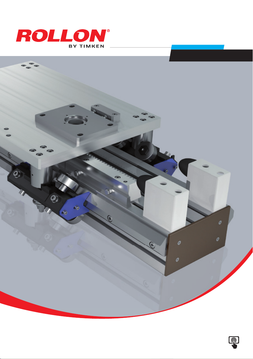
Timken Rollon Tecline User guide

www.rollon.com
Tecline
Interactive catalogs
on: www.rollon.com
Use and Maintenance
English

WARRANTY
In accordance with section 1512 of the Civil Code, Rollon S.p.A. guarantees the good performance of products manufactured
for one year after delivery, when their actual application is recommended by the Technical of Commercial Department of our
company provided that the report of poor operation is made in writing within eight days of its discovery. The warranty does not
cover damage or defects due to external agents, poor maintenance, overload, unsuitable lubricant, normal wear, inappropriate
choice of the type, installation error or other causes traceable to incorrect use or not imputable to the manufacture of the article.
The warranty is limited to repair and/or replacement, excluding major damage.

Tecline
UM-3
Warranty
Warnings and legal notes UM-4
Residual risks, Basic components, Tightening torque and traction vector values UM-5
Instructions of an environmental nature, Safety warnings for handling and transport,
Notes on lubrication UM-6
Note, Packaging UM-7
Transport, Handling and lifting, Check axis integrity after shipment UM-8
PAR - Main components list and spare parts UM-9
PAS - Main components list and spare parts UM-11
Routine maintenance
Manual greasing and lubrication, Automatic rack lubrication UM-13
Replacing the lubrication cartridge, Replacing the lubricator pinion UM-14
Extraordinary maintenance
Removal and replacement of the rack pinion, Removal and replacement of the drive shaft UM-15
Removal and replacement of the support bearing UM-16
Removal and replacement of the rack UM-17
PAR: carriage, sliders and guides replacement
Removal and replacement of the Y-axis carriages,
Removal and replacement of the Z-axis carriages UM-18
“V-shaped” rollers UM-19
Roller oscillating slides ø30 mm, ø40 mm, ø52 mm e ø62 mm UM-20
4 Rollers fixed slide ø40 mm, ø52 mm e ø62 mm UM-21
6 Rollers oscillating slides ø52 mm and ø62 mm UM-22
6 Rollers Single Fixed Slide Ø52 Mm E Ø62 Mm UM-23
Removal and replacement of the prismatic guides UM-24
PAS: sliders and guides replacement
Recirculating ball sliders UM-25
Recirculating ball guides UM-26
Accessories
Removal and replacement of the “rod locking” safety system (optional) UM-28
Removal and replacement of the stopper cylinder security system (optional) UM-29
Index

Use and Maintenance
UM-4
Warnings and legal notes
Before incorporating the partly completed machinery, we recom-
mend consulting this chapter carefully, in addition to the assembly
manual supplied with the individual modules. The information con-
tained in this chapter and in the manuals for the individual modules,
is provided by highly qualified and certified personnel, possessing
adequate competence in incorporating the partly completed ma-
chinery.
Avoid damage. Do not operate with inadequate tools
Precaution in installation and handling operations. Signifi-
cantly heavy equipment.
When handling the axis or system of axes, always make sure
that the support or anchoring surfaces do not leave room
for bending.
In order to stabilize the axis or system of axes, before han-
dling it is mandatory to securely block the mobile parts.
When moving axes with vertical translation (Z AXES) or
combination systems (horizontal X and/or more than one
vertical Z), it is mandatory to use the vertical movement to
put all of the axes at the corresponding lower limit switch.
Warning: moving parts. Do not leave objectson the axis
Do not overload. Do not subject to torsion stress.
Do not leave exposed to atmospheric agents.
Special installations: check the depth of the threads on
moving elements
Make sure that the system has been installed on a level
floor surface.
In use, accurately comply with the specific performance
values declared in the catalog or, in particular cases, the
load and dynamic performance characteristics requested
in the phase prior to design.
Before mounting the motor on the gearbox, it is advisable to
perform a pre-test of the motor itself, without connection to
the gear unit. The testing of this component was not carried
out by the manufacturer of the machine. It will therefore be
the responsibility of the customer of Rollon to perform the
testing of the same, in order to verify its correct operation.
For modules or parts of modular systems with vertical
movement (Z axis), it is mandatory to mount self-braking
motors to neutralize the risk of the axis dropping.
The images in this manual are to be considered merely an
indication and not binding; therefore, the supply received
could be different from the images contained in this man-
ual, and Rollon S.p.A has deemed it useful to insert only
one example.
Systems supplied by Rollon S.p.A. were not designed/en-
visaged to operate in ATEX environments.
The manufacturer cannot be considered responsible for any
consequences derived from improper use or any use other
than the purpose the axis or system of axes was designed
for, or derived from failure to comply, during incorporation
phases, with the rules of Good Technique and with what is
indicated in this manual.

Tecline
UM-5
The Partly Completed Machinery shown in this catalog is to be
considered a mere supply of simple Cartesian axes and their ac-
cessories agreed when the contract is stipulated with the client. The
following are therefore to be considered excluded from the contract:
1. Assembly on the client’s premises (direct or final)
2. Commissioning on the client’s premises (direct or final)
3. Testing on the client’s premises (direct or final)
It is therefore understood that the aforementioned operations
in points 1.,2., and 3. are not chargeable to Rollon. Rollon is the
supplier of Partly Completed Machinery, the (direct or final) client
• Mechanical risks due to the presence of moving elements (X, Y axes).
• Risk of fire resulting from the flammability of the belts used on the axes,
for temperatures in excess of 250 °C in contact with the flame.
• The risk of the Z axis dropping during handling and installation
operations on the partly completed machinery, before commissioning.
• Risk of the Z axis dropping during maintenance operations in the case
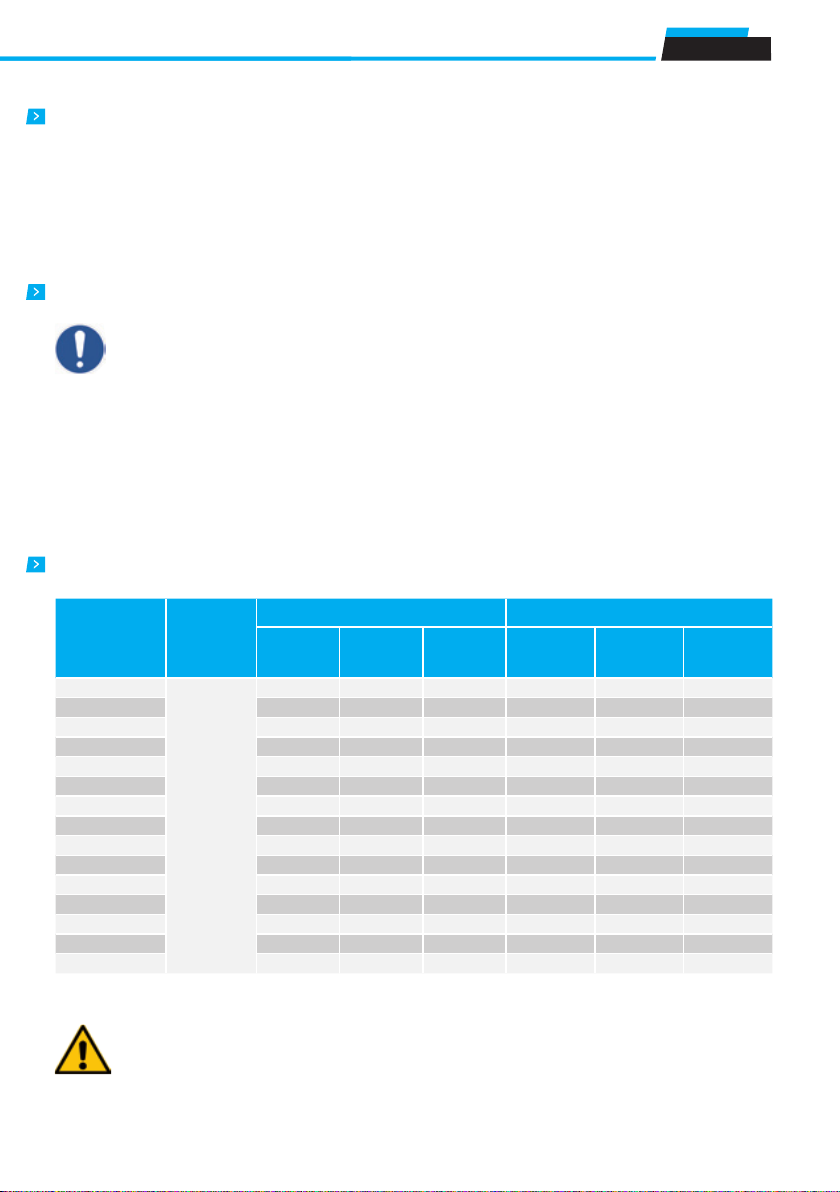
All the screws belong to the UNI-3740. Locking assemblies are provided with class 12.9 fastening screws.
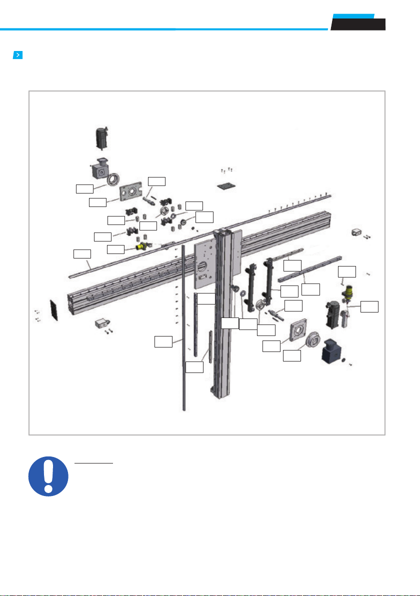
Basic components
Residual risks
Tightening torque and traction vector values
Thread
Friction
coefficient
Tightening torque [Nm] Traction vector [Nm]
Resistance
grade
8,8
Resistance
grade
10,9
Resistance
grade
12,9
Resistance
grade
8,8
Resistance
grade
10,8
Resistance
grade
12,8
M3
0,15
1,21 1,21 2,09 2075 3048 3567
M4 2,78 4,09 4,79 3594 5279 6178
M5 5,5 8,1 9,5 5886 8645 10116
M6 9,5 14,0 16,4 8302 12194 14269
M8 23 34 40 15242 22388 226498
M10 46 67 79 24275 35655 41724
M12 79 116 136 35401 51995 60845
M14 127 187 219 46816 71408 83563
M16 1998 291 341 66955 98340 115079
M18 283 402 471 8346 119454 139787
M20 402 570 667 107941 153657 179811
M22 552 783 917 134806 192157 224865
M24 691 981 1148 155489 221266 258928
M27 1022 1452 1700 204577 291534 341157
M30 1387 1969 2305 248811 354209 414500
is responsible for testing and safely checking all equipment whi-
ch, by definition, cannot be theoretically tested or checked at our
facilities where the only movement possible is manual movement
(for example: motors or reduction gears, cartesian axes movements
that are not manually operated, safety brakes, stopper cylinders,
mechanical or induction sensors, decelerators, mechanical limit
switches, pneumatic cylinders, etc.). The partly completed machine
must not be commissioned until the final machine, in which it is to
be incorporated, has been declared compliant, if necessary, with the
instructions in Machinery Directive 2006/42/CE.
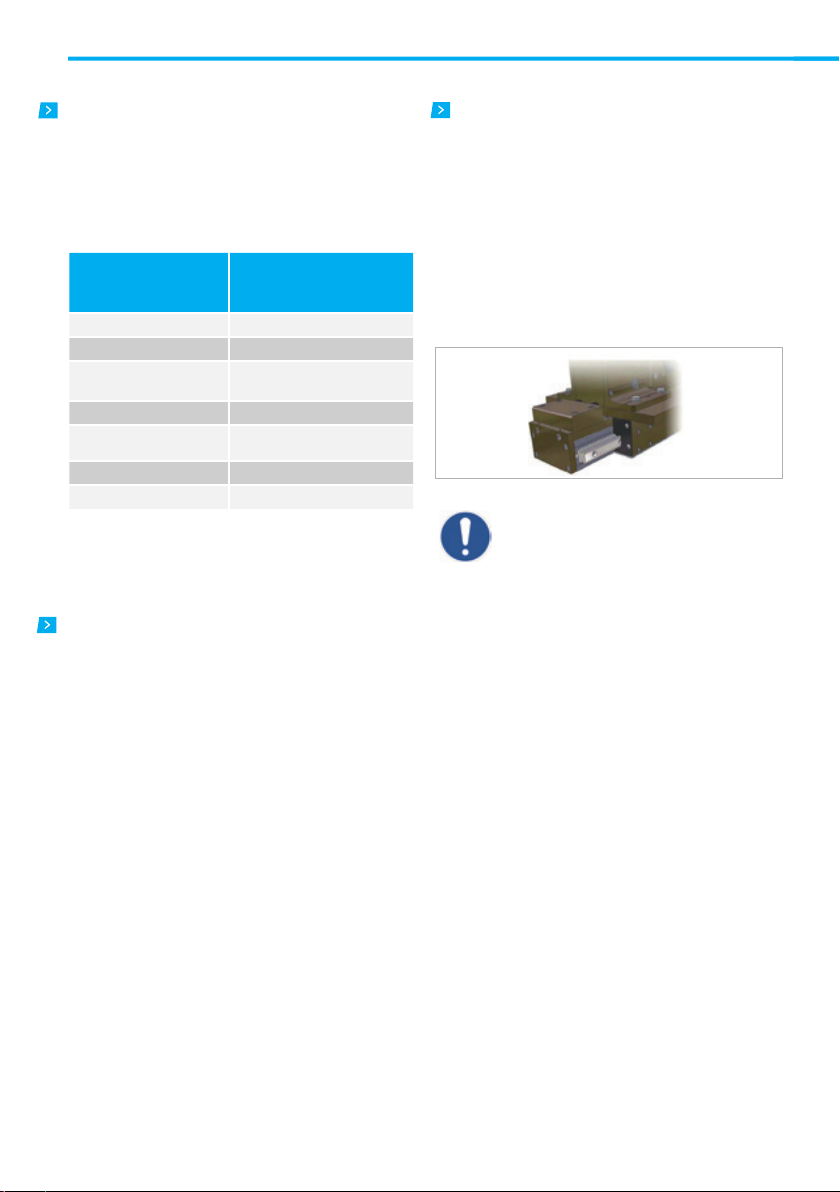
IMPORTANT!
All screws used for installing ROLLON modules have self-
locking washers or semi-permanent threadlock fluid (blue,
such as Loctite 243). We recommend that the user also
employ these devices, both while setting up the partially
assembled machine in this manual, and during the assembly
or maintenance phases: If this is not done, the manufacturer
of the partially assembled machine declines all responsibility
for any accidents, breakage, damage and the consequences
of said events on people, animals and property, due to the
failure of fixing elements.
of a drop in the electrical power supply voltage.
• Crushing hazard near moving parts with divergent and convergent
motion.
• Shearing hazard near moving parts with divergent and convergent
motion.
• Cutting and abrasion hazards.

Use and Maintenance
UM-6
Notes on lubrication
Safety warnings for handling and transport
Keep the prismatic rail lubricated using oil type VACTRA 2 every 1 year or
2000 km of operations. Keep recirculating ball sliders and rails lubricated
every 1 year or 2000 km of operations using greases between ISO VG 68
and ISO VG 100. In case of heavy loads it is necessary to use greases
type ISO VG 220.
• The manufacturer has paid the utmost attention to packaging to
minimize risks related to shipping, handling and transport.
• Transport can be facilitated by shipping certain components dismantled
and appropriately protected and packaged.
• Handling (loading and unloading) must be carried out in compliance
with information directly provided on the machine, on the packing and
in the user manuals.
• Personnel authorized to lift and handle the machine and its components
shall possess acquired and acknowledged skills and experience in the
specific sector, besides having full control of the lifting devices used.
• During transport and/or storage, temperature shall remain within the
allowed limits to avoid irreversible damage to electric and electronic
components.
• Handling and transport must be carried out with vehicles presenting
adequate loading capacity, and the machines shall be anchored to the
established points indicated on the axes.
• DO NOT attempt to bypass handling methods and the established lifting
points in any way.
• During handling and if required by the conditions, make use of one or
more assistants to receive adequate warnings.
• If the machine has to be moved with vehicles, ensure that they are
adequate for the purpose, and perform loading and unloading without
risks for the operator and for people directly involved in the process.
Never lubricate bearings type 2RS wherever they are present: the pres-
sure exerted during the operation would get the side seals out of seat.
• Before transferring the device onto the vehicle, ensure that both the
machine and its components are adequately secured, and that their
profile does not exceed the maximum bulk allowed. Place the necessary
warning signs, if necessary.
• DO NOT perform handling with an inadequate visual field and when
there are obstacles along the route to the final location.
• DO NOT allow people to either transit or linger within the range of action
when lifting and handling loads.
• Download the axes just near the established location and store them in
an environment protected against atmospheric agents.
• Failure to comply with the information provided might entail risks for the
safety and health of people, and can cause economic loss.
• The Installation Manager must have the project to organize and monitor
all operative phases.
• The Installation Manager shall ensure that the lifting devices and
equipment defined during the contract phase are available.
• The Manager of the established location and the Installation Manager
shall implement a “safety plan” in compliance with the legislation in
force for the workplace.
• The “safety plan” shall take into account all surrounding work-related
activities and the perimeter spaces indicated in the project for the es
tablished location.
• Mark and delimit the established location to prevent unauthorized
IMPORTANT!
The machine rails are protected with a layer of rust-proof
oil or specific grease. Use suitable gloves when handling.
Instructions of an environmental nature
Material
Details of the supply
Alluminum alloys Profiles, pleates, various details
Steel with various composition Screws, racks and pinions, and rails
Plastic
PA6 – Chains
PVC – Covers and sliding
block scrapers
Rubber of various types Plugs, seals
Lubrification of various types Used for the lubrication of sliding
rails and bearings
Rust proof protectione Rust proof protection oil
Wood, polyethylene, cardboard Transport packaging
Rollon operates with respect for the envirorment, in order to limit environ-
mental impact. The following is a list of some instructions of an environ-
mental nature for correct management of our supplies. Our products are
mainly composed of:
At the end of the product’s life cycle, it is therfore possible to recover the
various elements, in compliance with current regulations on waste issues.

Tecline
UM-7
Note
Fitting out the established location in advance allows to avoid wa-
sting the time of installation technicians.
personnel from accessing the installation area.
• The installation site must have adequate environmental conditions
(lighting, ventilation, etc.).
• Installation site temperature must be within the maximum and minimum
range allowed.
• Ensure that the installation site is protected against atmospheric agents,
does not contain corrosive substances and is free of the risk of
explosion and/or fire.
• Installation in environments presenting a risk of explosion and/or of fire
must ONLY be carried out if the machine has been DECLARED
COMPLIANT for such use.
• Check that the established location has been correctly fitted out, as
defined during the contract phase and based on indications in the
relative project.
• The established location must be fitted out in advance to carry out
complete installation in compliance with the defined methods and
schedule.
• Evaluate in advance whether the machine must interact with other
production units, and that integration can be implemented correctly, in
compliance with standards and without risks.
• The manager shall assign installation and assembly interventions ONLY
to authorized technicians with acknowledged know-how.
• State of the art connections to power sources (electric, pneumatic, etc.)
must be ensured, in compliance with relevant regulatory and legislative
requirements.
• “State of the art” connection, alignment and leveling are essential to
avoid additional interventions and to ensure correct machine function.
• Upon completion of the connections, run a general check to ascertain
that all interventions have been correctly carried out and compliance
with requirements.
• Failure to comply with the information provided might entail risks for the
safety and health of people, and can cause economic loss.
Packaging
The illustrations present the most common types of packaging used.
• Packaging is done keeping in mind the bulk reduction and the type of
transport chosen.
• Transport can be facilitated by shipping certain components dismantled
and appropriately protected and packaged.
• Some parts, particularly electric, are protected with anti-humidity nylon.
• Packaging for maritime transport is the “overseas” type to guarantee
preservation of the packaged elements.
• The packaging states all the necessary information for loading and
unloading.
• Every shipment is accompanied by a document (“Packing list”) with the
list and description of the axes.
• For shipments via road transport or in “open top” containers, axes that
are not covered by packaging are appropriately protected with a “barrier
bag”.
• Bulk components are appropriately placed along with the axes (with or
without packaging) to avoid sudden and unexpected movements.
• Bulk components that cannot be put together in packages shall be
deposited and appropriately secured to a pallet.
• The packaging material must be appropriately disposed of in compliance
with the legislation in force.
Packing on pallet
with nylon protection
Packing on pallet
with protective cage
Packing with
cardboard box
Packing in box

Use and Maintenance
UM-8
Transport
Handling and lifting
Check axis integrity after shipment
• Transport, also based on the final destination, can be done with different
vehicles.
• Perform transport with suitable devices that have adequate loading
capacity.
• Ensure that the machine and its components are adequately anchored
to the vehicle.
• Correctly connect the lifting devices to the established points on the
packages and/or on the dismantled parts.
• Before handling, read the instructions, especially safety instructions,
provided in the installation manual, on the packages and/or on the
dismantled parts.
• DO NOT attempt, in any way, to bypass handling methods and the
established lifting, moving and handling points of each package and/or
dismantled part.
• Slowly lift the package to the minimum necessary height and move it
with the utmost caution to avoid dangerous oscillations.
• DO NOT perform handling with an inadequate visual field and when
there are obstacles along the route to reach the final location.
• DO NOT allow people to either transit or linger within the range of action
when lifting and handling loads.
• Do not stack packages to avoid damaging them, and reduce the risk of
sudden and dangerous movements.
• In case of prolonged storage, regularly ensure that there are no
variations in the storage conditions of the packages.
Every shipment is accompanied by a document (“Packing list”) with the
list and description of the axes.
• Upon receipt check that the material received corresponds to specifica-
tions in the delivery note.
• Check that packaging is perfectly intact and, for shipments without
packaging, check that each axis is intact.
• In case of damages or missing parts, contact the manufacturer to define
the relevant procedures.

Tecline
UM-9
PAR - Main components list and spare parts
IMPORTANT!
Purely indicative picture, only to be taken as example.
PAR1
PAR2
PAR4
PAR5
PAR6
PAR7
PAR8
PAR3
PAR9
PAR12
PA R 19
PA R 13
PA R 14
PA R 22
PA R 11
PA R 15
PA R 16
PA R 17 PA R 10
PA R 20
PA R 26
PA R 18
PA R 23
PA R 24

Use and Maintenance
UM-10
Pos Description
PAR1 Bell-shaped flange axis-Z
PAR2 Mounting plate and gear registration axis-Z
PAR3 Drive shaft axis-Z
PAR4 Spacer carriages axis-Y
PAR5 Carriages axis-Y
PAR6 Flange bearing axis-Z
PAR7 Lubrication group axis-Z
PAR8 Prismatic guide axis-Y
PAR9 Support bearing axis-Z
PAR10 Lubrication group axis-Z
PAR11 Bell-shaped flange axis-Y
PAR12 Pinion axis-Z
PAR13 Prismatic guide axis-Z
PAR14 Pinion axis-Y
PAR15 Support bearing axis-Y
PAR16 Flange bearing axis-Y
PAR17 Drive shaft axis-Y
PAR18 Carriages axis-Z
PAR19 Bead rack axis-Y
PAR20 Rack axis-Y
PAR22 Mounting plate and gear registration axis-Y
PAR23 Rack axis-Z
PAR24 Tallone cremagliera axis- Z
PAR26 Cylindrical pin

Tecline
UM-11
PAS - Main components list and spare parts
IMPORTANT!
Purely indicative picture, only to be taken as example.

Use and Maintenance
UM-12
Pos Description
PAS1 Lubrication cartridge
PAS2 Lubrication pinion
PAS3 Energy chain
PAS4 Recirculating ball slides
PAS5 Drive pinion
PAS6 Ball bearing
PAS7 Drive shaft
PAS8 Rack
PAS9 Cylindrical pin
PAS10 Recirculating slides guide
PAS11 Bearing holder flange
PAS12 Rod locking safety system
PAS13 Mounting plate and registration gearbox
ATTENTION!
If the “Rod Locking” safety system has been
provided with the axis, the correct function-
ing of the fall-stop safety system must be
ensured by a device that releases the pres-
surised air from the pneumatic system each
time an emergency situation arises, due to
either electrical, electronic, mechanical or
pneumatic origin or human factors: the safety
system can only brake the load’s fall if this
condition is met.
Rollon S.p.A. shall not be held responsible if these conditions
are not met.

Tecline
UM-13
The scraper with felt (PAR axes) requires no special main-
tenance, it is sufficient its replacement every 12, 24 or 36
months according to the specific case. However, depending
on the dynamics incurred by the system, it may be necessary
to maintain the surface of the prismatic steel guides slightly
moistened, injecting into the scraper with felt cm3of grease
such as “Purpose”, consistency 2, every 500 hours or 10,000
km of operation.
The guides for the recirculating ball slides (PAS axes) must not
be lubricated. Provide greasing the slides for every 500 hours
or 10,000 km of operation, using grease
ranging between ISO VG 68 and ISO VG-100. In the case of
high loads must be used grease type ISO VG 220.
Automatic rack lubrication
Rack lubrication is provided by an automatic greasing system
(optional), which can be operated by an on/off switch located
in the rear part of the lubrication unit: this unit comprises a
replaceable cartridge, a pinion made form Vulkollan and ad-
justable lubrication frequency, depending on the particular
dynamic requirements.
Manual greasing and lubrication
For both PAR and PAS axes, never lubricate bearings type
2RS wherever they are present: the pressure exerted during
the operation would get the side seals out of seat. For axes
equipped with “Rod Locking” safety system unit, never lubri-
cate the sliding calibrated bar.
ATTENTION!
For instructions on routine and special maintenance and for the safety informations about the automatic
greasing system of the rack, refer to the specific manual assembly of the accessory in question.
ATTENTION!
The lubricator cartridge unit must be replaced before having completely run out,
otherwise abnormal consumption of the pinion or the rack may occur.
Routine maintenance

Use and Maintenance
UM-14
Replacing the lubrication cartridge
Replacing the lubricator pinion
a. open black plastic support “A”, by working
on the snap-in latch;
b. undo the lubricator from the L-support without
removing or damaging the grease pipe (C);
c. release the transparent rear cover and
remove the empty cartridge from the motor unit;
d. replace the empty cartridge;
e. perform the operations in reverse for refitting.
a. undo the socket head cap screws (A) and remove greasing
pipe (C) from the fitting so that unit (B) can be completely
removed from the base plate;
b. undo the countersunk hex head screws (D) and remove
washer (E);
c. remove the lubrication pinion from shaft (G) and replace it
with a new one;
d. perform the operations in reverse for refitting.
e. Before axis commissioning, make sure that the lubrication
pinion is soaked with grease again.

Tecline
UM-15
Removal and replacement of the rack pinion
a. remove the motor;
b. remove the hex head screws (A) securing the plate and
remove the plate;
c. undo countersunk hex head screws (B) securing the shaft
with the washer (C) for pinion (D);
d. remove pinion (D) and replace it with a new one;
e. perform the operations in reverse for refitting.
Extraordinary maintenance
Removal and replacement of the drive shaft
Proceed as follows to replace the drive shaft:
a. Remove the motor;
b. Remove the hex head screws (A) securing the plate and
remove the plate;
c. undo countersunk hex head screws (B) securing the shaft
with the washer (C) for pinion (D);

Use and Maintenance
UM-16
Proceed as follows to replace the rack pinion:
d. Remove the pinion (D).
e. Remove tab (E) from shaft (H).
f. Undo socket head cap screws (G) and remove the reduction
gear with the shaft from the plate.
g. Remove the head screw for connecting the shaft to the
reduction gear.
h. Remove the shaft from the reduction gear and remove key (I).
i. Replace the drive shaft.
j. Perform the operations in reverse for refitting.
Removal and replacement of the support bearing.
a. Remove the motor.
b. Remove the hex head screws (A) securing the plate and
remove the plate.
c. Undo countersunk hex head screws (B) securing the shaft
with the washer (C) for pinion (D).
d. Remove the pinion (D).
e. Remove tab (E) from shaft (H).
f. Undo socket head cap screws M10 (G) and remove the
reduction gear with the shaft from the plate.
g.
Remove the support bearing (F) from the flange and replace it.
h. Perform the operations in reverse for refitting.

Tecline
UM-17
To replace one or more rack segments it is necessary to
remove the axis from its vertical position and put it in horizon-
tal position. After this, secure it firmly and proceed as follows:
a. Remove the motor and the reduction gear but leave the
shaft and pinion fitted for the subsequent adjustment (refer
to section “Removal and replacement of the drive shaft”).
b. Move the carriage into a position that does not interfere
with the segment of rack to be replaced.
c. Remove plugs (A) using the correct removal tool.
d. Undo socket head cap screws (B).
e. Remove the rack segment concerned (C)
f. Check the positioning of the rack beads (D) and the M8
securing plugs inserted in the profile slot, and carefully
arrange the new segment of rack without working
on the grub screws mounted on the support beads (D)
g. Tighten screws (B) in the respective threaded plugs without
blocking them, to allow the subsequent adjustment
of the rack.
h. Insert plugs (A) in their housings, making sure they are
Removal and replacement of the rack
flush with the upper level of the rack. If one or more plugs
get damaged during the removal, they must be replaced
with equivalent plugs.
i. By moving the carriage slowly, manually check that the
pinion/rack clearance and the pitch on the joint of the
replaced segment are the same as the area in which
nothing has been worked on (for a starting reference do
more tests along the said section). If the clearance is
greater the rack needs to be brought closer to the pinion,
where the clearance is lower the rack needs to be moved
further away from the pinion. Once the clearance has
been properly adjusted, proceed with the final tightening
of the screws, at the end of which a new clearance check
is recommended.
If the clearance between the teeth is more than antic-
ipated, it will result in noisy and inaccurate movement
(especially for changes of direction). If the clearance
is lower, there will be abnormal consumption of the
teeth which would result in damage to the system. If
the pitch between the rack segments is incorrect, it
could cause serious damage to the teething.
j. Proceed with greasing the replaced segment. If the rack
segments to be replaced total more than one, you must
replace one segment at a time, to avoid losing the initial
references.
k. Perform the operation in reverse for refitting.

Use and Maintenance
UM-18
Removal and replacement of the Y-axis carriages
Removal and replacement of the Z-axis carriages
If replacing one or more carriages, it is recommended that the
utmost care is taken when handling the axes and remember
that is essential to work on one slider at a time.
a. Use any support to lock the plate.
b. Remove elements that hold the roller or the carriage on the
base plate (refer to the section dedicated to the type of
carriages or rollers on the axis).
c. Remove the carriage or the V-roller to be replaced.
d. Perform the operation in reverse for refitting the cart.
e. Check the preload setting of carriages (refer to the
section dedicated to thetype of carriages or rollers on the
axis).
a. Use any support to lock the vertical profile.
b. Remove the elements that fix the carriage or roller on the base
plate (refer to the section dedicated to type of carriages or
rollers on the axis).
c. Remove the carriage or the roller to be replaced.
d. Perform the operation in reverse for refitting the carriage and
check the setting of the preloading of carriages (refer to the
section dedicated to the type of carriages or rollers on the
axis).
PAR: carriage, sliders and guides replacement

Tecline
UM-19
“V-shaped” rollers
a. Loosen (clockwise or counterclockwise) the eccentric
rollers to retrieve the axial play on the axis on which it is
intervening.
b. Undo the screws (C) and remove the washer (D).
c. Remove the spacer (E), with the roller (F) still mounted.
d. Unscrew the nut (A) and remove the washer (B), then
remove the roller (F) and replace it with a new one.
e. Perform the operation in reverse for refitting.
Replacement:
Preloading setting:
To ensure the proper alignment and to minimize the clearance
during the translation, each axis is equipped with opposed
concentric and eccentric sliding bearings. Proceed as follows
to get the right preloading setting:
a. Loosen the nut (B);
b. Rotate the hexagonal pivot (A) until the roller will be
completely in contact with the guide (up to when it will be
possible to rotate the roller by hand).
c. Proceed with the tightening of the nut while holding the
exagonal pivot (A).

Use and Maintenance
UM-20
Roller oscillating slides ø30 mm, ø40 mm, ø52 mm e ø62 mm.
Replacement:
Preloading setting:
a. Unscrew the Ch24 self locking nut (A)
b. Loosen the STEI M6 grain (B) upon the locking pivot (C)
c. Unscrew (Ch10) and remove the locking pivot (C).
d. Now the slide is loose and it is removable.
e. Perform the operation in reverse for refitting, positioning
with care the two fifth-wheel with the teflon side in direct
contact with the slide replaced.
a. Loosen the Ch17 nut (A) of eccentric pivots.
b. Adjust the slide until all contact with the guide bearings,
turning the eccentric bushing (B) towards right or left.
c. Screw the Ch17 nut (A).
To ensure the proper alignment and to minimize the clearance
during the translation, each axis is equipped with opposed
concentric and eccentric sliding bearings. Proceed as follows
to get the right preloading setting:
Table of contents
Other Timken Industrial Equipment manuals

Timken
Timken ROLLON ELM Series User guide

Timken
Timken ROLLON S-SMART User guide

Timken
Timken ROLLON R-SMART Series User guide

Timken
Timken Rollon ROBOT User guide

Timken
Timken ROLLON E-SMART Series User guide

Timken
Timken Rollon ECO Series User guide

Timken
Timken ROLLON R-SMART Series User guide

Timken
Timken Sheave Pac NP954426-902A1 User manual