TKO 522DBS User manual

2
Owner’s Manual
DELUXE HEAVY BAG
STAND W/ PLATFORM
Model 522DBS
www.tko.com
V2.0—06.2012

3
THIS PAGE INTENTIONALLY LEFT BLANK

4
Safety
3
Read this owner’s manual carefully before assembling or using TKO equipment.
WARNING: Serious injury could occur if these safety precautions are not observed
Safety Precautions
•Before beginning any exercise program, consult your personal physician. Evaluate
your present fitness level and determine the exercise program that is most
appropriate for your particular age and condition.
•If you experience any pain or tightness in your chest, irregular heartbeats, shortness
of breath, faintness or other unusual discomfort while exercising, stop and consult
your physician before continuing.
•Make sure that the equipment(s) are set up and operated on a solid level surface.
DO NOT install or use the equipment on an uneven surface.
•Exercise equipment has moving parts. In the interest of safety, keep others,
especially children, at a safe distance while exercising.
•Make sure there are enough room for access and operate the equipment(s) safely.
•Inspect and maintain the equipment(s) regularly.
•Replace the worn or damaged parts / components immediately to ensure safety.
•Use a spotter.
•Back support cushion may drop when knob is pulled. Hold the back support cushion
when adjusting it.
•Make sure the pull pin is fully engaged before use.
•Lower the back support cushion to the lowest position when not in use.
•Warm up 5 to 10 minutes before each workout and cool down 5 to 10 minutes
afterward. Never hold your breath while exercising.
•Remove all jewelry, including rings, chains and pins before commencing exercise.
•Always wear suitable clothing and footwear during exercise. Do NOT wear loose
fitting clothing that could become entangled with the moving parts of your exercise
machine.
•Rest adequately between workouts. Muscles tone and develop during these rest
periods.
•Most exercise equipment is not recommended for small children. Children should
not use the machine unless they are under adult supervision.
If you have any question or need assistance please contact us at,
Customer Service: 866-856-3488 or 713-895-9270
Hours: Monday-Friday 8:30am to 4:30pm CT
©Copyright 2011, TKO Sports Group USA Limited. All rights reserved.
TKO Sports Group USA Limited. 4660 Pine Timbers, Suite 198, Houston, TX 77041
Phone + 713-895-9270 Fax + 713-934-8495
www.tko.com
✚Safety

5
Safety
BEFORE YOU BEGIN
Thank you for Purchasing TKO Fitness products.
TKO Fitness products are designed and manufactured to the highest standards in order to provide
you with years of great workouts. We proudly stand behind all our products with the best customer
service in the fitness industry. If you have any question or need assistance please contact us at:
CUSTOMER SERVICE: service@tkosportsgroup.com
Toll free: 866-856-3488 or 713-895-9270 Fax: 713-895-9379
Monday-Friday 8:30am to 4:30pm Central Standard Time
TKO hereby extends the following limited warranties for the following components of the equipment,
for the time period indicated:
FRAME.
TKO warrants this product to be free from defects in materials and workmanship for a period of 1
year from date of purchase, provided the product is used for its intended purpose, and provided the
product has not been subjected to obvious abuse, misuse or neglect. The extent of TKO’s liability
under this warranty is to defect to materials and workmanship, and is limited to the repair of such
defects or replacement of any equipment of part defective at the time of purchase. TKO shall not
have any liability to repair and/or replace said equipment or part if the purchaser uses the
equipment or part in contravention of the instructions provided by TKO, or if damage is caused by
the purchaser in any way.
COMPONENTS (HEAVY BAG / SPEED BAG / WOODEN PLATFORM / SWIVEL)
TKO warrants the components against defects in workmanship and material for a period of six
months from the date of original purchase, so long as the equipment remains in the possession of
the original owner.
Remove all parts from packaging and match against the parts list to ensure that all parts are present.
Read all assembly and operating instructions carefully before using this product.
All warnings and instructions should be followed to prevent personal injury and property damage.
Follow all directions when assembling, adjusting and using this product.
Inspect product for worn or broken parts before each use. Replace it before use it. Ensure all bolts
are tight and secure before each use.
Do not use this product in a commercial or institutional environment. This product is intended for
home use only.
Consult your physician prior to starting any fitness program. TKO cannot be responsible for the
misuse, unauthorized, or improper use of this product.
1

6
Safety
USAGE INSTRUCTIONS
TKO recommends using only TKO brand Heavy bag
TKO recommends that you use a heavy bag with a tie-down. Hang your heavy bag from the
assembled eye bolt (25) using the hardware provided with your heavy bag. The eye bolt (25) is
intentionally left open-ended to help hang your bag.
WARNING: When using a 75lb.Heavy bag or less, it is required that a
minimum of 50lbs.of standard weight plates (sold separately) be
placed on each of the three plate holders (6) to ensure the stability of
the unit. Do not use a heavy bag weighing more than 100 lbs.
If your heavy bag is equipped with a tie down option, tie to the tie down loop on the two R and L
bases shown.
Punch heavy bag as required by your workout regimen.
TKO recommends using only TKO brand Speed bag
Inflate your speed bag according to the manufacture’s instructions, and hang it from the swivel
assembly (13) attached to the wood platform (11)
To adjust the speed bag platform, loosen the knob (18) by turning it counterclockwise and turn
the handle of the spring loaded lock pin (9) counterclockwise until it begins to pop.
Place one hand on the handlebar (27) and use the other hand to pull the spring lock pin (9). Then
adjust the platform to the desired height.
Once in place, release the spring lock pin (9). A "click" sound be heard when the lock pin has fully
engauged to the hole in the speedbag platform frame.
Tighten the lock pin (9) and the knob (18) by turning the handles clockwise until snug. Use the
speed bag as requires by your workout regimen.
CAUTION: ALWAYS MAKE SURE THE KNOB AND LOCK PIN ARE
TIGHTENED BEFORE EXERCISE.
2

7
Product Diagram
Model # 522DBS
Heavy Bag/Speed Bag Workout Station

8
Exploded Diagram
EXPLODED DIAGRAM
PLEASE DO NOT RETURN TO STORE, CALL OUR CUSTOMER SERVICE DEPARTMENT
FIRST AT 1-866-856-3488 or 713-895-9270
4

9
Parts List
PARTS LIST
Part Numbers & Description
1L. Left Base Stabilizer (1pc)
1R. Right Base Stabilizer (1pc)
2. Center Base Frame (1pc)
3. Heavy Bag Angle Support Tube (1pc)
4L. Left Angle Support (1pc)
4R. Right Angle Support (1pc)
5. Curved Lower Upright (1pc)
6. Rod-Bolt Down Weight Horn (2pcs)
7. Rear Weight Horn w/M10x40 Hex Bolt (1pc)
8. Speed Bag Support Tube (1pc)
9. Spring Lock Pin (1pc)
10. M6 x 40mm Screw (4pcs)
11. Speed Bag Platform (1pc)
12. M8 x 45mm Screw (4pcs)
13. Swivel Hook (1pc)
14. Swivel Kit (1pc)
15. Square Plastic Bushing (2pcs)
16. Square Inner Plug (2pcs)
17. Round Foot Cap (4pcs)
18. Knob (1pc)
19. 1/4” Nylon Locknut (4pcs)
20. 1/4” Washer (4pcs)
21. 3/8” Washer (27pcs)
22. 3/8” Nylon Lock Nut (15pcs)
23. 3/8” x 4” Half Thread Hex Bolt (12pcs)
24. 1” Round Inner Plug (5pcs)
25. Heavy Bag Eye Bolt (1pc)
26. Sit-Up Rod (1pc)
27. Hand Grip (1pc)
28. Foam Cover (2pcs)
29. Anchor Bracket (2pcs)
30. Speed Bag Platform Support Plate (2pcs)
31. Dome Shaped End Cap (1pc)
32. 3/8” x 3-3/4” Screw (2pcs)
33. M8 Nylon Locknut (6pcs)
34. M8 Washer (8pcs)
35. Reinforcement Plate (2pcs)
36. M8 x 4” Half Thread Hex Bolt (2pcs)
37. M10 x 1” Washer (2pcs)
38. Swivel Plastic Cushion (1pc)
PLEASE DO NOT RETURN TO STORE, CALL OUR CUSTOMER SERVICE DEPARTMENT
FIRST AT 1-866-856-3488 or 713-895-9270
5
10
Assembly
ASSEMBLY INSTRUCTIONS
Note: Clean up an area at least 6’ by 6’ and a ceiling height of 7’3” high.
Before starting assembly remove all parts and hardware from the
carton and ensure you have everything according to the list.
Do not tighten nuts and bolts until you have completed all the
assembly steps.
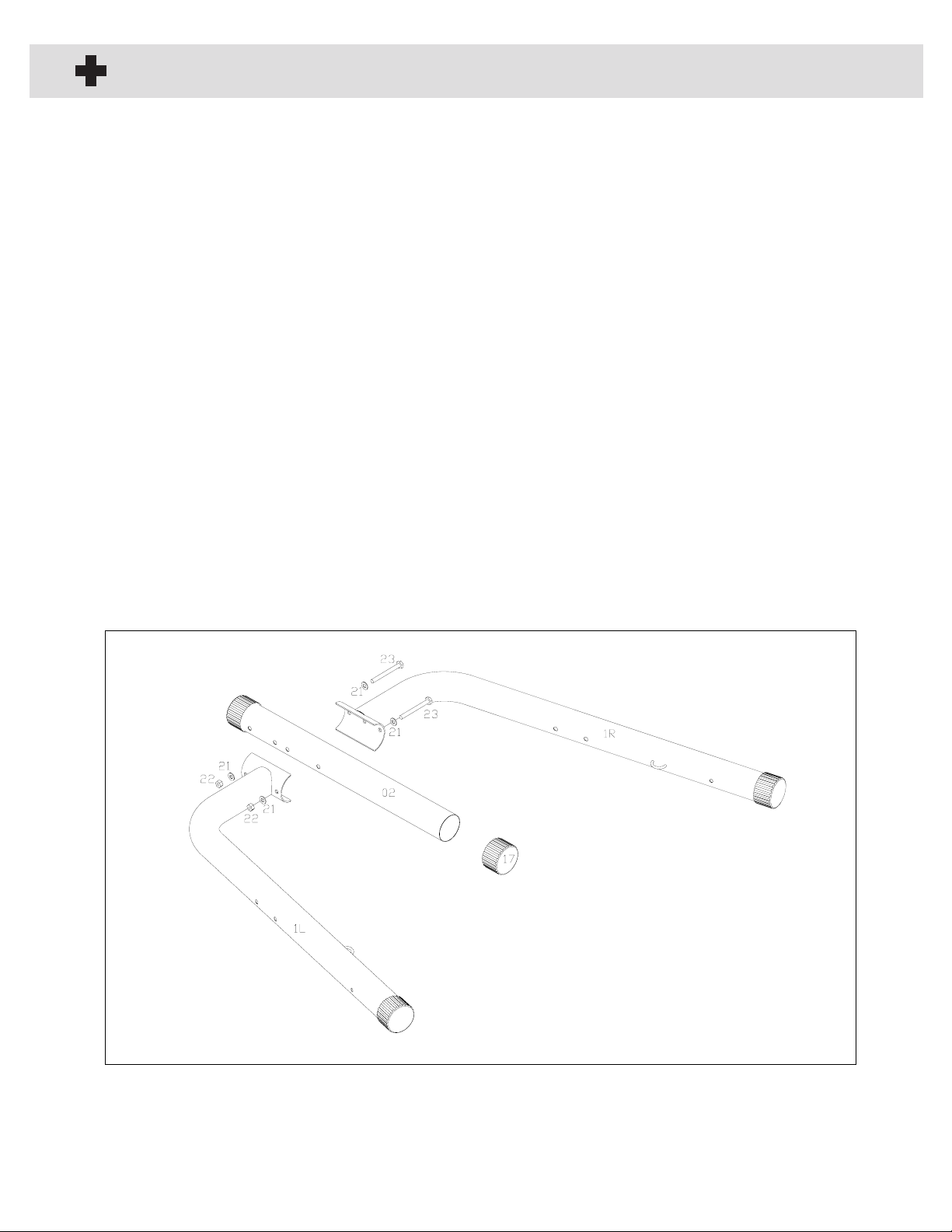
STEP 1.
Place Center Base Frame (2), the Left (1L) and Right (1R) Base Stabilizerson the floor as shown.
Align the Base Stabilizers with the first set of holes of the Center Base as shown. Use two Hex
Bolts (23), four Washers(21),and two Nylon Locknuts (22) to secure. If not pre-installed, insert
the Round Foot Cap (17) into the end of each Base Tube.
PLEASE DO NOT RETURN TO STORE, CALL OUR CUSTOMER SERVICE DEPARTMENT
FIRST AT 1-866-856-3488 or 713-895-9270
6

11
Assembly
ASSEMBLY INSTRUCTIONS
STEP 2.
Place the Mounting Bracket of the Curved Lower Upright (5) over the Center Base Frame. Aligning
the bolt holes with the second set of holes on the Center Base Frame, secure with two Hex Bolts (23),
four Washers (21),and two Nylon Locknuts (22).
Set the Left (4L) and Right (4R) Angle Supportsover the Left and Right Base Stabilizersas shown.
Use two Hex Bolts (23),four Washers (21),and two Nylon Locknuts (22) to secure each Angle
Support to the Base Stabilizer.
PLEASE DO NOT RETURN TO STORE, CALL OUR CUSTOMER SERVICE DEPARTMENT
FIRST AT 1-866-856-3488 or 713-895-9270
7

12
Assembly
ASSEMBLY INSTRUCTIONS
STEP 3
Insert the Heavy Bag Eye Bolt (25) into the end bolt hole on the Heavy Bag Angle Support Tube (3).
Attach from the top using one Washer (21) and one Nylon Locknut (22) and tighten,however leave
the bolt just loose enough that it can turn around in the bolt hole.
PLEASE DO NOT RETURN TO STORE, CALL OUR CUSTOMER SERVICE DEPARTMENT
FIRST AT 1-866-856-3488 or 713-895-9270
8

13
Assembly
ASSEMBLY INSTRUCTIONS
STEP 4
Slide the Heavy Bag Support Tube (3) between the Mounting Bracket of the Left and Right Angle
Supports, and then insert into the top of the Curved Lower Upright as shown. The Heavy Bag
Support should be facing the front of the Stand.
Align the holeson the Bracketsand the Heavy Bag Support Tube and secure using two Hex
Bolts (23),four Washers (21),and two Nylon Locknuts (22).
9
PLEASE DO NOT RETURN TO STORE, CALL OUR CUSTOMER SERVICE DEPARTMENT
FIRST AT 1-866-856-3488 or 713-895-9270

14
Assembly
ASSEMBLY INSTRUCTIONS
STEP 5
Install two Reinforcement Plates (35) around the connection position of the Curved Lower Upright
and the Heavy Bag Support Tube. Aligning the bolt holes,secure using two Hex Bolts (23),
four Washers (21),and two Nylon Locknuts (22).
10
PLEASE DO NOT RETURN TO STORE, CALL OUR CUSTOMER SERVICE DEPARTMENT
FIRST AT 1-866-856-3488 or 713-895-9270

15
Assembly
ASSEMBLY INSTRUCTIONS
STEP 6
Attach the Swivel hook (13), Swivel Kit (14),and Swivel Plastic Cushion (38) to the Speed
Bag Platform (11), with 4 Phillips Screws(10), 4 Washers (20),and 4 Lock Nuts(19). (This
has been pre-assembled in factory). Tighten it securely before you use it.
Mount each Speed Bag Platform Support Plate (30) to the Speed Bag Platform (11) using
two Screws (12),two Washers (34), and two Nylon Locknuts (33).
PLEASE DO NOT RETURN TO STORE, CALL OUR CUSTOMER SERVICE DEPARTMENT
FIRST AT 1-866-856-3488 or 713-895-9270
11

16
Assembly
ASSEMBLY INSTRUCTIONS
STEP 7
Attach the Speed Bag Platform (11) to the Speed Bag Support Tube (8) using two Screws (32),
two Washers (37),two Washers (21),and two Nylon Locknuts (22) as shown.
PLEASE DO NOT RETURN TO STORE, CALL OUR CUSTOMER SERVICE DEPARTMENT
FIRST AT 1-866-856-3488 or 713-895-9270
12

17
Assembly
ASSEMBLY INSTRUCTIONS
STEP 8
Loosen the Spring Pin (9) and T-Lock Pin (18), and slide the Speed Bag Support Tube into the
square holder on the rear of the Heavy Bag Angle Support Tube.
To adjust the height of the Speed Bag Platform: Loosen the T-Lock Pin, place one hand on the
handle at the bend of the Speed Bag Support Tube and use the other hand to pull the Spring Pin,
adjust the Platform to the desired height.
Once in place, release the Spring Pin such that it locates in one of the adjustment holes. Tighten
the Spring Pin and T-Lock Pin until snug.
13
PLEASE DO NOT RETURN TO STORE, CALL OUR CUSTOMER SERVICE DEPARTMENT
FIRST AT 1-866-856-3488 or 713-895-9270

18
Assembly
ASSEMBLY INSTRUCTIONS
STEP 9
Set each of the Rod-Bolt Down Weight Horns(6) on the end of the Base Stabilizer as shown.
Push oneHex Bolt (36) and one Washer (34) through one side of the Weight Horn Bracket of the
Base Stabilizer and out through the opposite side of the Weight Horn Bracket, then Anchor
Bracket (29). Secure the parts using one Washer (34) and a Nylon Locknut (33).
PLEASE DO NOT RETURN TO STORE, CALL OUR CUSTOMER SERVICE DEPARTMENT
FIRST AT 1-866-856-3488 or 713-895-9270
14

19
Assembly
ASSEMBLY INSTRUCTIONS
STEP 10
Insert the Sit-Up Rod (26) into the hole on the lower section of the Curved Lower Upright as
shown. Align the hole on the Sit-Up Rod with the hole on the rear of the Curved Lower Upright.
Secure with the threaded Bolt on the end of the Rear Weight Horn (07).
Install the Form Covers (28) onto each end of the Sit-Up Rod as shown.
PLEASE DO NOT RETURN TO STORE, CALL OUR CUSTOMER SERVICE DEPARTMENT
FIRST AT 1-866-856-3488 or 713-895-9270
15
20
Assembly
ASSEMBLY INSTRUCTIONS
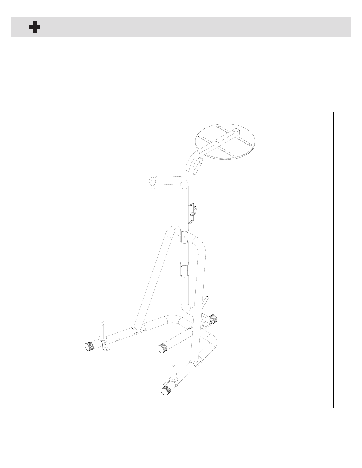
STEP 11
Tighten all nuts and bolts with wrenches at this time.
PLEASE DO NOT RETURN TO STORE, CALL OUR CUSTOMER SERVICE DEPARTMENT
FIRST AT 1-866-856-3488 or 713-895-9270
16
Table of contents
Other TKO Fitness Equipment manuals


