TLV SS1NL User manual

172-65390MA-04 (SS1 Series) 13 September 2021
Free Float Steam Trap
SS1NL / SS1NH
SS1VL / SS1VH
Copyright © 2021 by TLV CO., LTD.
All rights reserved

172-65390MA-04 (SS1 Series) 13 Sep 2021
1
Contents
Introduction .......................................................................1
Safety Considerations.......................................................2
Checking the Piping..........................................................4
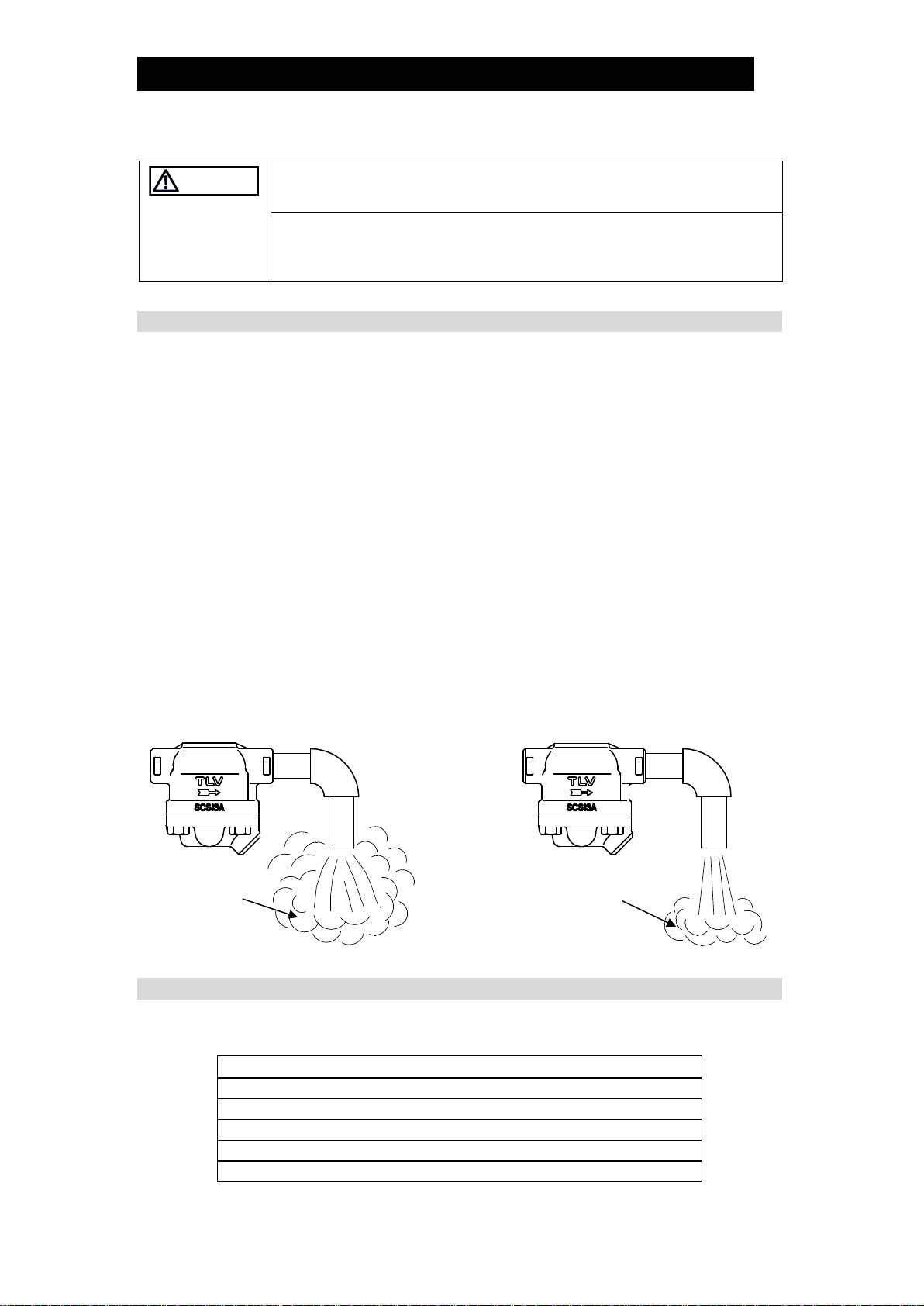
Operation ..........................................................................5
Specifications....................................................................6
Configuration.....................................................................7
Installation.........................................................................8
Maintenance......................................................................9
Disassembly/Reassembly...............................................10
Troubleshooting ..............................................................13
TLV EXPRESS LIMITED WARRANTY...........................14
Service............................................................................16
Introduction
Thank you for purchasing the TLV free float steam trap.
This product has been thoroughly inspected before being shipped from the
factory. When the product is delivered, before doing anything else, check the
specifications and external appearance to make sure nothing is out of the
ordinary. Also be sure to read this manual carefully before use and follow the
instructions to be sure of using the product properly.
This free float steam trap uses a precision-ground float and three-point
support for the valve body. With no hinges or levers, the trap automatically
continuously discharges condensate, preventing it from collecting.
The three-point seating for the valve body supports the precision-ground float
securely at three points and ensures a high degree of sealing when even
only minute quantities of condensate are present.
This free float steam trap is ideal for places at which extremely small
amounts of condensate are generated, such as superheated and saturated
steam mains and branches, and trace lines.
If detailed instructions for special order specifications or options not contained
in this manual are required, please contact TLV for full details.
This instruction manual is intended for use with the model(s) listed on the
front cover. It is necessary not only for installation but also for any
troubleshooting required. Please keep it in a safe place for future reference.

172-65390MA-04 (SS1 Series) 13 Sep 2021
2
Safety Considerations
•Read this section carefully before use and be sure to follow the instructions.
•Installation, inspection, maintenance, repairs, disassembly, adjustment and valve
opening/closing should be carried out only by trained maintenance personnel.
•The precautions listed in this manual are designed to ensure safety and prevent
equipment damage and personal injury. For situations that may occur as a result
of erroneous handling, three different types of cautionary items are used to
indicate the degree of urgency and the scale of potential damage and danger:
DANGER, WARNING and CAUTION.
•The three types of cautionary items above are very important for safety: be sure to
observe all of them as they relate to installation, use, maintenance, and repair.
Furthermore, TLV accepts no responsibility for any accidents or damage occurring
as a result of failure to observe these precautions.
Symbols
Indicates a DANGER, WARNING or CAUTION item.
Indicates an urgent situation which poses a threat of death or
serious injury
Indicates that there is a potential threat of death or serious injury
Indicates that there is a possibility of injury or equipment/product
damage
NEVER apply direct heat to the float.
The float may explode due to increased internal pressure,
causing accidents leading to serious injury or damage to property
and equipment.
Install properly and DO NOT use this product outside the
recommended operating pressure, temperature and other
specification ranges.
Improper use may result in such hazards as damage to the
product or malfunctions that may lead to serious accidents. Local
regulations may restrict the use of this product to below the
conditions quoted.
DO NOT use this product in excess of the maximum
operating pressure differential.
Such use could make discharge impossible (blocked).
Take measures to prevent people from coming into direct
contact with product outlets.
Failure to do so may result in burns or other injury from the
discharge of fluids.
Continued on the next page
DANGER
WARNING
CAUTION
WARNING
CAUTION

172-65390MA-04 (SS1 Series) 13 Sep 2021
3
When disassembling or removing the product, wait until the
internal pressure equals atmospheric pressure and the
surface of the product has cooled to room temperature.
Disassembling or removing the product when it is hot or under
pressure may lead to discharge of fluids, causing burns, other
injuries or damage.
Be sure to use only the recommended components when
repairing the product, and NEVER attempt to modify the
product in any way.
Failure to observe these precautions may result in damage to the
product and burns or other injury due to malfunction or the
discharge of fluids.
Use only under conditions in which no freeze-up will occur.
Freezing may damage the product, leading to fluid discharge,
which may cause burns or other injury.
Use only under conditions in which no water hammer will
occur.
The impact of water hammer may damage the product, leading to
fluid discharge, which may cause burns or other injury.
CAUTION

172-65390MA-04 (SS1 Series) 13 Sep 2021
4
Checking the Piping
Use only under conditions in which no water hammer will occur.
The impact of water hammer may damage the product, leading to fluid
discharge, which may cause burns or other injury.
Check to make sure that the pipes to be connected to the trap have been installed
properly.
1. Is the pipe diameter suitable?
2. Is the piping where the trap is to be installed horizontal (for the SS1NL/SS1NH)
or vertical (for the SS1VL/SS1VH)?
3. Has sufficient space been secured for maintenance?
4. Have maintenance valves been installed at the inlet and outlet?
If the outlet is subject to back pressure, has a check valve (TLV-CK) been
installed?
5. Is the inlet pipe as short as possible, with as few bends as possible, and installed
so the liquid will flow naturally down into the trap?
6. Has the piping work been done correctly, as shown in the figures below?
Requirement
Correct
Incorrect
Install catchpot with the
proper diameter.
Diameter is too small.
Make sure the flow of
condensate is not
obstructed.
Diameter is too small and
inlet protrudes into pipe
interior.
To prevent rust and scale
from flowing into the trap,
the inlet pipe should be
connected 25 – 50 mm
(1 – 2 in) above the base
of the T-pipe.
Rust and scale flow into
the trap with the
condensate.
When installing on the
blind end, make sure the
flow of condensate is not
obstructed.
Condensate collects in the
pipe.
CAUTION

172-65390MA-04 (SS1 Series) 13 Sep 2021
5
Operation
Principles of air and condensate discharge:
1.
Start-up Air and Cold Condensate
Discharge
At start-up, before steam is supplied,
the system is cold and the bimetal air
vent strip is contracted, holding the
float off of the valve seat. This allows
for the rapid discharge of air and cold
condensate through the valve when
steam is first supplied to the system.
2.
Condensate Discharge
If the temperature of the condensate
rises above 90°C (194°F), the bimetal
air vent strip expands allowing the
float to block the valve seat. Rising
condensate levels cause the float to
rise due to buoyancy, opening the
valve and allowing hot condensate to
be discharged.
3.
Closed Position
When the condensate flow rate
decreases, the float falls, closing off
the valve seat opening.
A water seal is maintained at all times
over the valve seat opening to prevent
steam loss.
Air
Steam
Condensate

172-65390MA-04 (SS1 Series) 13 Sep 2021
6
Specifications
Install properly and DO NOT use this product outside the recommended
operating pressure, temperature and other specification ranges.
Improper use may result in such hazards as damage to the product or
malfunctions that may lead to serious accidents. Local regulations may restrict
the use of this product to below the conditions quoted.
DO NOT use the product in excess of the maximum operating pressure
differential; such use could make discharge impossible (blocked).
Use only under conditions in which no freeze-up will occur. Freezing may
damage the product, leading to fluid discharge, which may cause burns or other
injury
Refer to the product nameplate for detailed specifications.
SS1NL/SS1NH
SS1VL/SS1VH
A
Nominal Diameter
B
Maximum Allowable Pressure (PMA)*
C
Maximum Operating Pressure (PMO)
D
Valve No.**
E
Model
F
Production Lot No.
G
Maximum Allowable Temperature (TMA)*
H
Maximum Operating Temperature (TMO)
* Maximum allowable pressure (PMA) and maximum allowable temperature (TMA) are
PRESSURE SHELL DESIGN CONDITIONS, NOT OPERATING CONDITIONS.
** Valve No. is displayed for products with options. This item is omitted from the
nameplate when there are no options.
CAUTION
E
B*
F
C
H
G*
D**
A
A
B*
G*
H
C
D**
F
E

172-65390MA-04 (SS1 Series) 13 Sep 2021
7
Configuration
SS1NL/SS1NH
SS1VL/SS1VH
No.
Name
M
R
F
1
Body
2
Cover
3
Float
4
Valve Seat
5
Valve Seat Gasket
6
Screen
7
Cover Gasket
8
Cover Bolt
9
Air Vent Strip
(Bimetal)
10
Screw
11
Spring Washer
12
Nameplate
13
Flange
14
Connector
No.
Name
M
R
F
1
Body
2
Cover*
3
Float
4
Valve Seat
5
Valve Seat Gasket
6
Screen
7
Cover Gasket
8
Cover Bolt
9
Air Vent Strip
(Bimetal)
10
Screw
11
Spring Washer
12
Nameplate
13
Flange
14
Connector
* Includes attached float guides
Replacement parts are available
only in the following kits:
M = Maintenance Kit
R = Repair Kit
F = Float

172-65390MA-04 (SS1 Series) 13 Sep 2021
8
Installation
Install properly and DO NOT use this product outside the recommended
operating pressure, temperature and other specification ranges.
Improper use may result in such hazards as damage to the product or
malfunctions that may lead to serious accidents. Local regulations may restrict
the use of this product to below the conditions quoted.
Take measures to prevent people from coming into direct contact with
product outlets. Failure to do so may result in burns or other injury from the
discharge of fluids.
1. Before installation, be sure to remove all protective seals.
2. Before installing the product, open the inlet valve and blow out the piping to
remove any piping scraps, dirt and oil. Close the inlet valve after blowdown.
3. Install the product so the arrow on the body is pointing in the direction of
condensate flow.
4. The product must be installed within the allowable angles of inclination of 5°
horizontally and front-to-back.
5. Install a condensate outlet valve and outlet piping.
6. Open the inlet and outlet valves and check to make sure that the product
functions properly.
If there is a problem, determine the cause using the “Troubleshooting” section in this
manual.
Tolerance Angle for Installation: 5°
SS1NL/SS1NH (Horizontal Installation Model)
SS1VL/SS1VH (Vertical Installation Model)
CAUTION

172-65390MA-04 (SS1 Series) 13 Sep 2021
9
Maintenance
Take measures to prevent people from coming into direct contact with
product outlets. Failure to do so may result in burns or other injury from the
discharge of fluids.
Be sure to use only the recommended components when repairing the
product, and NEVER attempt to modify the product in any way. Failure to
observe these precautions may re
sult in damage to the product or burns or other
injury due to malfunction or the discharge of fluids.
Operational Check
A visual inspection of the following items should be done on a daily basis to
determine whether the product is operating properly or has failed. Periodically (at
least biannually) the operation should also be checked by using diagnostic
equipment, such as a stethoscope, thermometer, or TLV TrapMan.
If the product should fail, it may cause damage to piping and equipment, resulting in
faulty or low quality products or losses due to steam leakage.
Normal
:
Condensate is discharged continuously, together with flash steam,
and the sound of flow can be heard.
Blocked
(Discharge Impossible)
:
No condensate is discharged. The product is quiet and makes no
noise, and the surface temperature of the trap is low.
Blowing
:
Live steam continually flows from the outlet and there is a
continuous metallic sound.
Steam Leakage
:
Live steam is discharged through the product outlet together with
condensate, accompanied by a high-pitched sound.
(When conducting a visual inspection, flash steam is sometimes mistaken for steam leakage.
For this reason, the use of a steam trap diagnostic instrument [TLV TrapMan] in conjunction
with the visual inspection is highly recommended.)
Parts Inspection
When parts have been removed, or during periodic inspections, use the following
table to inspect the parts and replace any that are found to be defective.
Procedure
Gasket(s): Check for warping and damage
Screen: Check for clogging and corrosion
Float: Check for scratches, dents, etc.
Valve Seat: Check for damage
Valve Seat Opening: Check for rust, scale, oil film, wear or damage
CAUTION
White jet
containing
water droplets
Flash Steam
Clear, slightly
bluish jet
Live Steam Leakage

172-65390MA-04 (SS1 Series) 13 Sep 2021
10
Disassembly/Reassembly
NEVER apply direct heat to the float.
The float may explode due to increased internal pressure, causing accidents
leading to serious injury or damage to property and equipment.
When disassembling or removing the product, wait until the internal
pressure equals atmospheric pressure and the surface of the product has
cooled to room temperature.
Disassembling or removing the product when it is
hot or under pressure may lead to discharge of fluids, causing burns, other
injuries or damage.
Use the following procedures to remove components. Use the same procedures in
reverse to reassemble. (Installation, inspection, maintenance, repairs, disassembly,
adjustment and valve opening/closing should be carried out only by trained
maintenance personnel.)
Detaching/Reattaching the Cover
Part
During Disassembly
During Reassembly
Cover Bolt 8
Remove with a socket wrench
Consult the table of tightening torques and
tighten to the proper torque
Cover 2
Remove carefully; take care to
prevent any damage to the float,
which may fall out when the
cover is removed
Make sure the sealing surfaces are clean,
then reattach;
SS1VL/ SS1VH only: be careful not to bend
the float guides (Fig. A)
Float 3
Remove, being careful not to
scratch the polished surface
Place inside the body (or on the cover), being
careful not to scratch its polished surface
Connector 14
Remove the connector
Insert into the hole in the cover
Cover
Gasket 7
SS1NH/SS1VH: Remove and
clean sealing surfaces on the
cover and body
Replace with a new gasket
SS1NL/SS1VL: Remove only if
damaged
Replace with a new gasket if damaged
Figure A
Disassembly/Reassembly of Components Inside the Body
Part
During
Disassembly
During
Reassembly
Figure B
Screw w/
Spring
Washer
10, 11
Remove screws
with a philips
screwdriver
Consult the table of
tightening torques
and tighten to the
proper torque
Screen 6
Remove without
bending; remove
any scale build-
up on the surface
Insert into body,
aligning screw
holes (Fig. B)
WARNING
CAUTION
Float Guides
(SS1VL/SS1VH only)
NOTE: The float guides are correctly positioned
when shipped from the factory, so be
careful when handling them. Tight
sealing cannot be guaranteed if the float
guides have been moved out of position.
Screw with
Spring
Washer
Screen
Body

172-65390MA-04 (SS1 Series) 13 Sep 2021
11
Disassembly/Reassembly of Components Inside the Cover
Part
During Disassembly
During Reassembly
Screw,
Spring Washer
10, 11
Remove with a phillips
screwdriver
Consult the table of tightening torques and
tighten to the proper torque
Air Vent Strip
(Bimetal) 9
Remove without bending
Insert without bending
Valve Seat 4
Remove with a socket wrench
Consult the table of tightening torques and
tighten to the proper torque
Valve Seat
Gasket 5
Remove the gasket and clean
sealing surfaces
Replace with a new gasket
Table of Tightening Torques
Cover Bolt
Valve Seat
Screw
Torque
Distance Across
Flats
Torque
Distance Across
Flats
Torque
Screw
Head
N∙m
(lbf·ft)
mm
(in)
N∙m
(lbf·ft)
mm
(in)
N∙m
(lbf·ft)
45 (33) 17 (
21
/32) 20 (15) 13 (
1
/2) 0.3 (0.22) +
NOTE:
-Coat all threaded portions with anti-seize.
-If drawings or other special documentation were supplied for the
product, any torque given there takes precedence over values
shown here.
(1 N⋅m ≈10 kg⋅cm)

172-65390MA-04 (SS1 Series) 13 Sep 2021
12
Exploded View
No.
Part Name
1
Body
2
Cover
3
Float
4
Valve Seat
5
Valve Seat Gasket
6
Screen
7
Cover Gasket
8
Cover Bolt
9
Air Vent Strip
(Bimetal)
10
Screw
11
Spring Washer
12
Nameplate
13
Flange
14
Connector
1
6
10,11
3
7
10,11
14
9
2
8
5
4
SS1N
SS1V
1
6
3
7
2
8
10,11
2
9
10,
11
4
5
14

172-65390MA-04 (SS1 Series) 13 Sep 2021
13
Troubleshooting
NEVER apply direct heat to the float.
The float may explode due to increased internal pressure, causing accidents
leading to serious injury or damage to property and equipment.
When disassembling or removing the product, wait until the internal
pressure equals atmospheric pressure and the surface of the product has
cooled to room temperature.
Disassembling or removing the product when it is
hot or under pressure may lead to discharge of fluids, causing burns, other
injuries or damage.
When the product fails to operate properly, use the following table to locate the
cause and remedy.
Problem
Cause
Remedy
No condensate is
discharged
(blocked) or
discharge is poor
The float is damaged or filled with
condensate
Replace with a new float
The float is sticking to the valve seat
Clean parts
The valve seat opening, screen or piping
are clogged with rust and scale
Clean parts
The capacity of the trap is insufficient
Compare specifications and
actual operating conditions
The trap operating pressure exceeds the
maximum specified pressure or there is
insufficient pressure differential between
the trap inlet and outlet
Compare specifications and
actual operating conditions
Steam-locking has occurred
Perform a bypass blowdown
or close the trap inlet valve
and allow the trap to cool
Steam is
discharged or
leaks from the
outlet
(blowing)
(steam leakage)
The valve seat opening is clogged or
there is rust or scale build-up on the
surface of the float
Clean parts
The valve seat is damaged
Replace with a new valve seat
The float is damaged
Replace with a new float
The installation is not correct
Correct the installation
The air vent strip (bimetal) is damaged
Replace with a new air vent
strip (bimetal)
Trap vibration
Lengthen the inlet piping and
fasten it securely
Steam is leaking
from a place
other than the
outlet
Gasket deterioration or damage
Replace with a new gasket
Improper tightening torques were used
Tighten to the proper torque
NOTE: When replacing parts with new, use the parts list for reference, and replace with parts
from the maintenance kit, repair kit, etc. Please note that replacement parts are only
available as part of a replacement parts kit.
WARNING
CAUTION

172-65390MA-04 (SS1 Series) 13 Sep 2021
14
TLV EXPRESS LIMITED WARRANTY
Subject to the limitations set forth below, TLV CO., LTD., a Japanese corporation
(“TLV”), warrants that products which are sold by it, TLV International Inc. (“TII”) or one
of its group companies excluding TLV Corporation (a corporation of the United States of
America), (hereinafter the “Products”) are designed and manufactured by TLV, conform
to the specifications published by TLV for the corresponding part numbers (the
“Specifications”) and are free from defective workmanship and materials. The party
from whom the Products were purchased shall be known hereinafter as the “Seller”.
With regard to products or components manufactured by unrelated third parties (the
“Components”), TLV provides no warranty other than the warranty from the third party
manufacturer(s), if any.
Exceptions to Warranty
This warranty does not cover defects or failures caused by:
1. improper shipping, installation, use, handling, etc., by persons other than TLV,
TII or TLV group company personnel, or service representatives authorized by
TLV; or
2. dirt, scale or rust, etc.; or
3. improper disassembly and reassembly, or inadequate inspection and
maintenance by persons other than TLV or TLV group company personnel, or
service representatives authorized by TLV; or
4. disasters or forces of nature or Acts of God; or
5. abuse, abnormal use, accidents or any other cause beyond the control of TLV,
TII or TLV group companies; or
6. improper storage, maintenance or repair; or
7. operation of the Products not in accordance with instructions issued with the
Products or with accepted industry practices; or
8. use for a purpose or in a manner for which the Products were not intended; or
9. use of the Products in a manner inconsistent with the Specifications; or
10. use of the Products with Hazardous Fluids (fluids other than steam, air, water,
nitrogen, carbon dioxide and inert gases (helium, neon, argon, krypton, xenon
and radon)); or
11. failure to follow the instructions contained in the TLV Instruction Manual for the
Product.
Duration of Warranty
This warranty is effective for a period of one (1) year after delivery of Products to the
first end user. Notwithstanding the foregoing, asserting a claim under this warranty
must be brought within three (3) years after the date of delivery to the initial buyer if
not sold initially to the first end user.
ANY IMPLIED WARRANTIES NOT NEGATED HEREBY WHICH MAY ARISE BY
OPERATION OF LAW, INCLUDING THE IMPLIED WARRANTIES OF MERCHANTABILITY
AND FITNESS FOR A PARTICULAR PURPOSE AND ANY EXPRESS WARRANTIES NOT
NEGATED HEREBY, ARE GIVEN SOLELY TO THE INITIAL BUYER AND ARE LIMITED IN
DURATION TO ONE (1) YEAR FROM THE DATE OF SHIPMENT BY THE SELLER.
Exclusive Remedy
THE EXCLUSIVE REMEDY UNDER THIS WARRANTY, UNDER ANY EXPRESS
WARRANTY OR UNDER ANY IMPLIED WARRANTIES NOT NEGATED HEREBY
(INCLUDING THE IMPLIED WARRANTIES OF MERCHANTABILITY AND FITNESS FOR A
PARTICULAR PURPOSE), IS REPLACEMENT; PROVIDED: (a) THE CLAIMED DEFECT IS

172-65390MA-04 (SS1 Series) 13 Sep 2021
15
REPORTED TO THE SELLER IN WRITING WITHIN THE WARRANTY PERIOD, INCLUDING
A DETAILED WRITTEN DESCRIPTION OF THE CLAIMED DEFECT AND HOW AND WHEN
THE CLAIMED DEFECTIVE PRODUCT WAS USED; AND (b) THE CLAIMED DEFECTIVE
PRODUCT AND A COPY OF THE PURCHASE INVOICE IS RETURNED TO THE SELLER,
FREIGHT AND TRANSPORTATION COSTS PREPAID, UNDER A RETURN MATERIAL
AUTHORIZATION AND TRACKING NUMBER ISSUED BY THE SELLER. ALL LABOR
COSTS, SHIPPING COSTS, AND TRANSPORTATION COSTS ASSOCIATED WITH THE
RETURN OR REPLACEMENT OF THE CLAIMED DEFECTIVE PRODUCT ARE SOLELY
THE RESPONSIBILITY OF BUYER OR THE FIRST END USER. THE SELLER RESERVES
THE RIGHT TO INSPECT ON THE FIRST END USER’S SITE ANY PRODUCTS CLAIMED
TO BE DEFECTIVE BEFORE ISSUING A RETURN MATERIAL AUTHORIZATION. SHOULD
SUCH INSPECTION REVEAL, IN THE SELLER’S REASONABLE DISCRETION, THAT THE
CLAIMED DEFECT IS NOT COVERED BY THIS WARRANTY, THE PARTY ASSERTING
THIS WARRANTY SHALL PAY THE SELLER FOR THE TIME AND EXPENSES RELATED
TO SUCH ON-SITE INSPECTION.
Exclusion of Consequential and Incidental Damages
IT IS SPECIFICALLY ACKNOWLEDGED THAT THIS WARRANTY, ANY OTHER EXPRESS
WARRANTY NOT NEGATED HEREBY, AND ANY IMPLIED WARRANTY NOT NEGATED
HEREBY, INCLUDING THE IMPLIED WARRANTIES OF MERCHANTABILITY AND FITNESS
FOR A PARTICULAR PURPOSE, DO NOT COVER, AND NEITHER TLV, TII NOR ITS TLV
GROUP COMPANIES WILL IN ANY EVENT BE LIABLE FOR, INCIDENTAL OR
CONSEQUENTIAL DAMAGES, INCLUDING, BUT NOT LIMITED TO LOST PROFITS, THE
COST OF DISASSEMBLY AND SHIPMENT OF THE DEFECTIVE PRODUCT, INJURY TO
OTHER PROPERTY, DAMAGE TO BUYER’S OR THE FIRST END USER’S PRODUCT,
DAMAGE TO BUYER’S OR THE FIRST END USER’S PROCESSES, LOSS OF USE, OR
OTHER COMMERCIAL LOSSES. WHERE, DUE TO OPERATION OF LAW,
CONSEQUENTIAL AND INCIDENTAL DAMAGES UNDER THIS WARRANTY, UNDER ANY
OTHER EXPRESS WARRANTY NOT NEGATED HEREBY OR UNDER ANY IMPLIED
WARRANTY NOT NEGATED HEREBY (INCLUDING THE IMPLIED WARRANTIES OF
MERCHANTABILITY AND FITNESS FOR A PARTICULAR PURPOSE) CANNOT BE
EXCLUDED, SUCH DAMAGES ARE EXPRESSLY LIMITED IN AMOUNT TO THE
PURCHASE PRICE OF THE DEFECTIVE PRODUCT. THIS EXCLUSION OF
CONSEQUENTIAL AND INCIDENTAL DAMAGES, AND THE PROVISION OF THIS
WARRANTY LIMITING REMEDIES HEREUNDER TO REPLACEMENT, ARE INDEPENDENT
PROVISIONS, AND ANY DETERMINATION THAT THE LIMITATION OF REMEDIES FAILS
OF ITS ESSENTIAL PURPOSE OR ANY OTHER DETERMINATION THAT EITHER OF THE
ABOVE REMEDIES IS UNENFORCEABLE, SHALL NOT BE CONSTRUED TO MAKE THE
OTHER PROVISIONS UNENFORCEABLE.
Exclusion of Other Warranties
THIS WARRANTY IS IN LIEU OF ALL OTHER WARRANTIES, EXPRESS OR IMPLIED,
AND ALL OTHER WARRANTIES, INCLUDING BUT NOT LIMITED TO THE IMPLIED
WARRANTIES OF MERCHANTABILITY AND FITNESS FOR A PARTICULAR PURPOSE,
ARE EXPRESSLY DISCLAIMED.
Severability
Any provision of this warranty which is invalid, prohibited or unenforceable in any
jurisdiction shall, as to such jurisdiction, be ineffective to the extent of such invalidity,
prohibition or unenforceability without invalidating the remaining provisions hereof,
and any such invalidity, prohibition or unenforceability in any such jurisdiction shall
not invalidate or render unenforceable such provision in any other jurisdiction.

172-65390MA-04 (SS1 Series) 13 Sep 2021
16
Service
For Service or Technical Assistance: Contact your TLV representative or your regional TLV office.
In Europe:
Daimler-Benz-Straße 16-18, 74915 Waibstadt, Germany
Tel:
Fax:
[49]-(0)7263-9150-0
[49]-(0)7263-9150-50
Units 7 & 8, Furlong Business Park, Bishops Cleeve, Gloucestershire GL52
8TW, U.K.
Tel:
Fax:
[44]-(0)1242-227223
[44]-(0)1242-223077
Parc d’Ariane 2, bât. C, 290 rue Ferdinand Perrier, 69800 Saint Priest,
France
Tel:
Fax:
33–(0)4-72482222
[33]-(0)4-72482220
In North America:
13901 South Lakes Drive, Charlotte, NC 28273-6790, U.S.A.
Tel:
Fax:
[1]-704-597-9070
[1]-704-583-1610
In Mexico and Latin America:
Av. Jesús del Monte 39-B-1001, Col. Hda. de las Palmas, Huixquilucan,
Edo. de México, 52763, Mexico
Tel:
Fax:
[52]-55-5359-7949
[52]-55-5359-7585
In Oceania:
Unit 8, 137-145 Rooks Road, Nunawading, Victoria 3131, Australia
Tel:
Fax:
[61]-(0)3-9873 5610
[61]-(0)3-9873 5010
In East Asia:
36 Kaki Bukit Place, #02-01/02, Singapore 416214
Tel:
Fax:
[65]-6747 4600
[65]-6742 0345
Room 5406, No. 103 Cao Bao Road, Shanghai, China 200233
Tel:
Fax:
[86]-(0)21-6482-8622
[86]-(0)21-6482-8623
No.16, Jalan MJ14, Taman Industri Meranti Jaya, 47120 Puchong,
Selangor, Malaysia
Tel:
Fax:
[60]-3-8065-2928
[60]-3-8065-2923
252/94 (K-L) 17th Floor, Muang Thai-Phatra Complex Tower B,
Rachadaphisek Road, Huaykwang, Bangkok 10310, Thailand
Tel:
Fax:
[66]-2-693-3799
[66]-2-693-3979
#302-1 Bundang Technopark B, 723 Pangyo-ro, Bundang, Seongnam,
Gyeonggi, 13511, Korea
Tel:
Fax:
[82]-(0)31-726-2105
[82]-(0)31-726-2195
In the Middle East:
Building 2W, No. M002, PO Box 371684, Dubai Airport Free Zone, Dubai, UAE
Email:
sales-[email protected]
In Other Countries:
881 Nagasuna, Noguchi, Kakogawa, Hyogo 675-8511, Japan
Tel:
Fax:
[81]-(0)79-427-1818
[81]-(0)79-425-1167
Manufacturer:
881 Nagasuna, Noguchi, Kakogawa, Hyogo 675-8511, Japan
Tel:
Fax:
[81]-(0)79-422-1122
[81]-(0)79-422-0112
Other manuals for SS1NL
2
This manual suits for next models
3
Table of contents
Other TLV Control Unit manuals