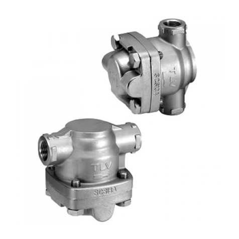
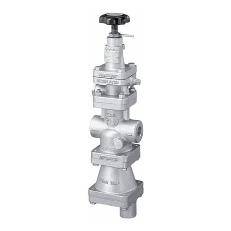
TLV DR20 User manual

DR20 A-DR20
Copyright (C) by TLV CO., LTD. All rights reserved.
DIRECT-ACTING PRESSURE REDUCING
VALVES FOR STEAM AND/OR AIR
TYP DR20/A-DR20
DIREKT WIRKENDE DRUCKREDUZIERVENTILE
FÜR DAMPF UND/ODER DRUCKLUFT
DÉTENDEUR-RÉGULATEURS À ACTION
DIRECTE POUR VAPEUR ET/OU AIR
MODÈLE DR20/A-DR20
MODEL DR20/A-DR20
INSTRUCTION MANUAL
Keep this manual in a safe place for future reference
EINBAU- UND BETRIEBSANLEITUNG
Gebrauchsanleitung leicht zugänglich aufbewahren
MANUEL D UTILISATION
Conserver ce manuel dans un endroit facile d'accès
Deutsch
Français
English

Introduction
Before beginning installation or maintenance, please read this manual to ensure correct use of
the product. Keep the manual in a safe place for future reference.
The DR20 direct-acting pressure reducing valve for steam and air is capable of reducing from
primary pressures of between 0.2 and 1.6 MPaG (30 – 230 psig) to secondary pressures between
0.014 and 1.0 MPaG (2 – 150 psig).
The A-DR20 direct-acting pressure reducing valve for air is capable of reducing from primary
pressures of between 0.2 and 1.0 MPaG (30 – 150 psig) to secondary pressures between 0.014
and 0.9 MPaG (2 – 135 psig).
They are designed for a long service life, and are made of stainless steel for superior durability.
1 MPa = 10.197 kg/cm
2
, 1 bar = 0.1 MPa
For products with special specifications or with options not included in this manual, contact TLV
for instructions.
The contents of this manual are subject to change without notice.
Einführung
Bitte lesen Sie die Betriebsanleitung vor Einbau und Inbetriebnahme sorgfältig durch und
bewahren Sie sie für späteren Gebrauch an einem leicht zugänglichen Ort auf.
Das direkt wirkende Druckreduzierventil DR20 für Dampf und Druckluft wird eingesetzt für einen
Vordruckbereich zwischen 2 und 16 bar ü und einen Minderdruckbereich zwischen 0,14 und 10
bar ü.
Das direkt wirkende Druckreduzierventil A-DR20 für Druckluft wird eingesetzt für einen
Vordruckbereich zwischen 2 und 10 bar ü und einen Minderdruckbereich zwischen 0,14 und 9
bar ü.
Die komplett aus Edelstahl bestehenden Ventile sind konzipiert für lange Lebensdauer und
außerordentliche Verschleißfestigkeit.
1 bar = 0,1 MPa
Wenden Sie sich an TLV für Sonderausführungen, die nicht in dieser Einbau- und
Betriebsanleitung enthalten sind.
Wir behalten uns vor, den Inhalt dieser Betriebsanleitung ohne Ankündigung zu ändern.
Veuillez lire attentivement ce manuel afin de vous assurer d’utiliser correctement le produit. Nous
vous recommandons de le garder dans un endroit sûr pour de futures références.
Le détendeur-régulateur DR20 pour vapeur et air permet de réduire une pression amont comprise
entre 2 et 16 bar à une pression aval comprise entre 0,14 et 10 bar.
Le détendeur-régulateur A-DR20 pour air permet de réduire une pression amont comprise entre 2
et 10 bar à une pression aval comprise entre 0,14 et 9 bar.
Ils sont conçu pour une longue durée de service: entièrement fait en acier inoxydable, ils sont
d’une durabilité supérieure.
1 bar = 0,1 MPa
Pour tout produit aux spécifications particulières ou comportant des options non reprises dans ce
manuel, veuillez contacter TLV.
Le contenu de ce manuel est sujet à modifications sans préavis.
Introduction
Deutsch
Français
English
1

1. Safety Considerations
• Read this section carefully before use and be sure to follow the instructions.
• Installation, inspection, maintenance, repairs, disassembly, adjustment and valve
opening/closing should be carried out only by trained maintenance personnel.
• The precautions listed in this manual are designed to ensure safety and prevent equipment
damage and personal injury. For situations that may occur as a result of erroneous handling,
three different types of cautionary items are used to indicate the degree of urgency and the
scale of potential damage and danger: DANGER, WARNING and CAUTION.
• The three types of cautionary items above are very important for safety; be sure to observe all
of them, as they relate to installation, use, maintenance, and repair. Furthermore, TLV accepts
no responsibility for any accidents or damage occurring as a result of failure to observe these
precautions.
Indicates an urgent situation that poses a threat of death or serious injury.
Indicates a DANGER, WARNING or CAUTION item.
Indicates that there is a potential threat of death or serious injury.
CAUTION
WARNING
DANGER
CAUTION Indicates that there is a possibility of injury, or equipment/product damage.
Install properly and DO NOT use this product outside the recommended
operating pressure, temperature and other specification ranges.
Improper use may result in such hazards as damage to the product or
malfunctions, which may lead to serious accidents. Local regulations may
restrict the use of this product to below the conditions quoted.
Take measures to prevent people from coming into direct contact
with product outlets.
Failure to do so may result in burns or other injury from the discharge of
fluids.
Do not use excessive force when connecting threaded pipes to the
product.
Over-tightening may cause breakage leading to fluid discharge, which
may cause burns or other injury.
When disassembling or removing the product, wait until the internal
pressure equals atmospheric pressure and the surface of the product
has cooled to room temperature.
Disassembling or removing the product when it is hot or under pressure
may lead to discharge of fluids, causing burns, other injuries or damage.
Be sure to use only the recommended components when repairing
the product, and NEVER attempt to modify the product in any way.
Failure to observe these precautions may result in damage to the product
or burns or other injury due to malfunction or the discharge of fluids.
Use only under conditions in which no freeze-up will occur.
Freezing may damage the product, leading to fluid discharge, which may
cause burns or other injury.
Use under conditions in which no water hammer will occur.
The impact of water hammer may damage the product, leading to fluid
discharge, which may cause burns or other injury.
English
2

1. Sicherheitshinweise
• Bitte lesen Sie dieses Kapitel vor Beginn der Arbeiten sorgfältig durch und befolgen Sie die
Vorschriften.
• Einbau und Ausbau, Inspektion, Wartungs- und Reparaturarbeiten, Öffnen/Schließen von
Armaturen, Einstellung von Komponenten, dürfen nur von geschultem Wartungspersonal
vorgenommen werden.
• Die Sicherheitshinweise in dieser Einbau- und Betriebsanleitung dienen dazu, Unfälle,
Verletzungen, Betriebsstörungen und Beschädigungen der Anlagen zu vermeiden. Für
Gefahrensituationen, die durch falsches Handeln entstehen können, werden drei verschiedene
Warnzeichen benutzt: GEFAHR; WARNUNG; VORSICHT.
• Diese drei Warnzeichen sind wichtig für Ihre Sicherheit. Sie müssen unbedingt beachtet
werden, um den sicheren Gebrauch des Produktes zu gewährleisten und Einbau, Wartung und
Reparatur ohne Unfälle oder Schäden durchführen zu können. TLV haftet nicht für Unfälle oder
Schäden, die durch Nichtbeachtung dieser Sicherheitshinweise entstehen.
Dieses Zeichen weist auf GEFAHR; WARNUNG; VORSICHT hin.
VORSICHT
Die Einbauhinweise beachten und die spezifizierten Betriebsgrenzen
NICHT ÜBERSCHREITEN. Nichtbeachtung kann zu Betriebsstörungen
oder Unfällen führen. Lokale Vorschriften können zur Unterschreitung der
angegebenen Werte zwingen.
In sicherer Entfernung von Auslassöffnungen aufhalten und andere
Personen warnen, sich fernzuhalten. Nichtbeachtung kann zu
Verletzungen durch austretende Fluide führen.
Vor Öffnen des Gehäuses und Ausbau von Teilen warten, bis der
Innendruck sich auf Atmosphärendruck gesenkt hat und das
Gehäuse auf Raumtemperatur abgekühlt ist. Nichtbeachtung kann zu
Verbrennungen oder Verletzungen durch austretende Fluide führen.
Zur Reparatur nur Original-Ersatzteile verwenden und NICHT
VERSUCHEN, das Produkt zu verändern. Nichtbeachtung kann zu
Beschädigungen führen, die Betriebsstörungen, Verbrennungen oder
andere Verletzungen durch austretende Fluide verursachen.
Bei Schraubanschlüssen keine übermäßige Kraft anwenden, damit
die Gewinde nicht beschädigt werden, was zu Verbrennungen oder
Verletzungen durch austretende Fluide führt.
Nur in frostsicherer Umgebung einsetzen. Einfrieren kann das Produkt
beschädigen, was zu Verbrennungen oder Verletzungen durch
austretende Fluide führt.
Nur an Stellen einbauen, an denen kein Wasserschlag eintreten
kann. Wasserschlag kann das Produkt beschädigen und zu
Verbrennungen oder Verletzungen durch austretende Fluide führen.
bedeutet, dass eine unmittelbare Gefahr für Leib und Leben besteht.
bedeutet, dass die Möglichkeit der Gefahr für Leib und Leben besteht.
WARNUNG
GEFAHR
VORSICHT
bedeutet dass die Möglichkeit von Verletzungen oder Schäden an
Anlagen oder Produkten besteht.
Deutsch
3

1. Règles de sécurité
• Lire attentivement cette notice avant l’utilisation et suivre les instructions.
• Tout installation, inspection, entretien, réparation, démontage, ajustement et
ouverture/fermeture de vanne doit être fait uniquement par une personne formée à l’entretien.
• La liste des précautions à prendre est établie afin d’assurer votre sécurité et de prévenir des
dégâts matériels et/ou des blessures sérieuses. Dans certaines situations causées par une
mauvaise manipulation, trois indicateurs sont utilisés afin d’indiquer le degré d’urgence,
l’échelle du dommage potentiel et le danger: DANGER, AVERTISSEMENT et ATTENTION.
• Ces 3 indicateurs sont importants pour votre sécurité; observez les précautions de sécurité
énumérées dans ce manuel pour l’installation, l’utilisation, l'entretien et la réparation du produit.
TLV n’accepte aucune responsabilité en cas d’accident ou de dommage survenant à la suite
d'un non-respect de ces précautions.
Indique une situation d’urgence avec risque de mort ou de blessure grave.
Indique un DANGER, un AVERTISSEMENT ou recommande une ATTENTION.
Indique une situation pouvant entraîner la mort ou des blessures graves.
ATTENTION
AVERTISSEMENT
DANGER
ATTENTION
Indique un risque de blessure ou de dégât matériel au produit et/ou aux
installations.
Installer le produit correctement et NE PAS l'utiliser en dehors de la
pression et de la température maximales de fonctionnement, ni en
dehors des autres plages spécifiées. Une telle utilisation peut entraîner
des dommages au produit ou des dysfonctionnements, ce qui peut
provoquer des brûlures ou autres blessures. Il se peut que des règlements
locaux limitent l'utilisation du produit en-deçà des spécifications indiquées.
Prendre les mesures appropriées afin d’éviter que des personnes
n’entrent en contact direct avec les ouvertures du produit. Le non-
respect de cette règle peut provoquer des brûlures ou autres blessures
sérieuses dues à l’écoulement des fluides.
Ne pas utiliser de force excessive lors de la connexion du produit à
la tuyauterie. Le non-respect de cette règle peut provoquer la rupture
du produit et mener a l’écoulement des fluides, causant des brûlures ou
blessures sérieuses.
En cas de démontage ou de manipulation du produit, attendre que
la pression interne soit égale à la pression atmosphérique et que la
surface du produit soit complètement refroidie. Le non-respect de
cette règle peut provoquer des brûlures ou autres dommages dûs à
l’écoulement des fluides.
En cas de réparation, utiliser uniquement les composants
spécifiques du produit et NE JAMAIS ESSAYER de modifier le
produit. Le non-respect de cette règle peut entraîner des dommages au
produit, ou des brûlures et autres blessures sérieuses dues au
dysfonctionnement du produit ou à l’écoulement des fluides.
N'utiliser que dans des conditions où le gel ne se produit pas. Le gel
peut endommager le produit et provoquer l’écoulement des fluides, et
causer des brûlures ou autres blessures sérieuses.
Utiliser le produit dans des conditions où il n’y a aucun coup de
bélier. L’impact d'un coup de bélier peut endommager le produit et
provoquer l’écoulement des fluides, ainsi que des brûlures ou des
blessures graves.
Français
4

2. Configuration Aufbau Configuration
18
17
20
16
2
1
3
4
5
6
7
19
9
10
11
12
13
14
15
8
10
22
22
21
*1
Replacement parts are available
only in the following kits:
A: Maintenance kit
B: Repair kit for Spacer
C: Repair kit for main Valve
D: Repair kit for bellows
*2Number of parts: 2 pieces
*3Shipped as a unit
1
2
3
4
5
6
7
8
9
10
11
12
13
14
15
16
17
18
19
20
21
22
1
2
3
4
5
6
7
8
9
10
11
12
13
14
15
16
17
18
19
20
21
22
Body
Cover
Screen
Coil Spring
Main Valve
Valve Seat Gasket
Valve Seat
Spacer*3
Snap Ring
Valve Stem
Bellows
Cover Gasket
Coil Spring
Spring Guide
Steel Ball
Cover Bolt
Locknut
Adjustment Handle
Nameplate
Retaining Ring
Slide Bearing*2 *3
Snap Ring*2 *3
Description Bauteil Désignation
No. Nr.
1
2
3
4
5
6
7
8
9
10
11
12
13
14
15
16
17
18
19
20
21
22
No.
Gehäuse
Gehäusedeckel
Schmutzsieb
Druckfeder
Hauptventil
Ventilsitzdichtung
Ventilsitz
Abstandsstück*3
Federring
Ventilstößel
Faltenbalg
Deckeldichtung
Druckfeder
Federhalterung
Stahlkugel
Gehäuseschraube
Kontermutter
Einstellgriff
Typenschild
Haltering
Gleitlager*2 *3
Federring*2 *3
Corps
Couvercle
Crépine
Ressort spiral
Soupape principale
Joint siège de soupape
Siège de soupape
Entretoise*3
Anneau ressort
Tige de soupape
Soufflet
Joint de couvercle
Ressort spiral
Guide du ressort
Boulet en acier
Boulon de couvercle
Contre-écrou
Poignée d’ajustement
Plaquette nominative
Anneau d’écartement
Palier lisse*2 *3
Bague d’écartement*2 *3
A*1B*1
D*1
C*1
A*1B*1D*1
C*1
A*1B*1
D*1
C*1
*1
Ersatzteile werden nur in den
folgenden Ersatzteilsätzen geliefert:
A: Wartungssatz
B:
Reparatursatz für Abstandsstück
C: Reparatursatz für Hauptventil
D: Reparatursatz für Faltenbalg
*2Anzahl der Bauteile: 2 Teile
*3Werden als Einheit verschickt
*1
Les pièces de remplacement ne sont
disponibles que sous la forme de jeux
de pièces suivants :
A: Jeu de pièces d’entretien
B:
Jeu de pièces de réparation pour l’entretoise
C:
Jeu de pièces de réparation pour la soupape principale
D:
Jeu de pièces de réparation pour le soufflet
*2Nombre de pièces : 2 pièces
*3Expédié comme unité
For A-DR20: Rubber (standard: fluorine
rubber) is used in the seating area. The
rubber is inlaid in the main valve.
Für A-DR20: Die Ventilsitzdichtung ist
aus Kunststoff (Standard: Kunststoff)
und als Einlage im Hauptventil
integriert.
Pour le A-DR20: Le caoutchouc (en
standard: fluorine) est utilisé sur la
surface d'usure. Le caoutchouc est
serti dans la vanne principale.
Soft Seat (Fluorine rubber)
Weichdichtender Ventilsitz
(Fluorkautschuk)
Portée souple
(caoutchouc fluorine)
DR20 A-DR20
5
English
Deutsch
Français

3. Exploded View Einzelteile Pièces détachées
Adjustment Handle
Einstellgriff
Poignée d’ajustement
Locknut
Kontermutter
Contre-écrou
Cover Bolt
Gehäuseschraube
Boulon de couvercle
Cover
Gehäusedeckel
Couvercle
Retaining Ring
Spannring
Anneau d'écartement
Steel Ball
Stahlkugel
Boulet en acier
Spring Guide
Federhalterung
Guide du ressort
Coil Spring
Druckfeder
Ressort spiral
Bellows
Faltenbalg
Soufflet
Snap Ring
Federring
Anneau ressort
Valve Stem
Ventilstößel
Tige de soupape
Valve Seat
Ventilsitz
Siège de soupape
Valve Seat Gasket
Ventilsitzdichtung
Joint siège de soupape
Main Valve**
Hauptventil**
Soupape principale**
Coil Spring
Druckfeder
Ressort spiral
Screen
Schmutzsieb
Crépine
Body
Gehäuse
Corps
Cover Gasket
Deckeldichtung
Joint de couvercle
Snap Ring*
Federring*
Bague d'écartement*
Slide Bearing*
Gleitlager*
Palier lisse*
Spacer
Abstandsstück
Entretoise
Slide Bearing*
Gleitlager*
Palier lisse*
Snap Ring*
Federring*
Bague d'écartement*
*Cannot be removed individually as it is incorporated with the spacer and must be replaced as a
set with the spacer.
** For A-DR20: The rubber is inlaid in the main valve and cannot be removed. The main valve
itself must be replaced.
*Gleitlager und Federring können nicht individuell ausgebaut werden, da sie am Abstandsstück
fixiert sind. Diese Teile müssen mit dem Abstandsstück zusammen ausgetauscht werden.
** Für A-DR20: Die Kunststoffeinlage im Hauptventil kann nicht entnommen werden. Zum
Austausch das Hauptventil ersetzen.
*Le palier lisse et la bague d'écartement ne peuvent pas être retirés seuls puisqu'ils sont fixés à
l'entretoise. Pour remplacer ces pièces, il faut remplacer l'entretoise en entier.
** Pour le A-DR20: Le caoutchouc est serti dans la vanne principale et ne peut être enlevé. La
vanne principale doit être remplacée.
6
Deutsch
Français
English

B
C
D
A
G
E
F
LOT
INLET P.
OUTLET P.
MADE IN JAPAN
SIZE MAX.T.
4.
Specifications Technische Daten Données techniques
Refer to the product nameplate for detailed specifications.
Die technischen Daten stehen auf dem Typenschild.
Les données techniques sont inscrites sur la plaquette nominative.
* Valve No. is displayed for products with options. This item
is omitted from the nameplate when there are no options.
* Die Valve No. wird angegeben bei Typen mit Optionen.
Bei Typen ohne Optionen bleibt diese Stelle frei.
* Le Valve No. est indiqué pour des modèles avec options.
Ce numéro ne figure pas sur les modèles sans options.
A. Model
Typ
Modèle
C. Nominal Diameter
Größe/DN
Dimension/DN
E. Maximum Operating Temperature
Maximale Betriebstemperatur
Température de fonctionnement maximale
G. Valve No.*
Die Einbauhinweise beachten und die spezifizierten Betriebsgrenzen
NICHT ÜBERSCHREITEN. Nichtbeachtung kann zu Betriebsstörungen
oder Unfällen führen. Lokale Vorschriften können zur Unterschreitung
der angegebenen Werte zwingen.
VORSICHT
To avoid malfunctions, product damage, accidents or serious injury,
install properly and DO NOT use this product outside the specification
range. Local regulations may restrict the use of this product to below
the conditions quoted.
CAUTION
Installer le produit correctement et NE PAS I'utiliser en dehors des plages
spécifiées. En cas de dépassement des limites données, des dysfonc-
tionnements ou accidents pourraient survenir. Il se peut que des règlements
locaux limitent l'utilisation du produit en-deçà des spécifications indiquées.
ATTENTION
Operating Range Betriebsdaten Plage de fonctionnement
Model Typ Modèle
Primary Pressure Range
Vordruckbereich
Plage de pressions amont
0.2 – 1.6 MPaG
2 – 16 barg
30 – 230 psig
0.6 – 1.6 MPaG
6 – 16 barg
85 – 230 psig
0.54 – 1.0 MPaG
5.4 – 10 barg
76 – 150 psig
0.18 – 0.6 MPaG
1.8 – 6 barg
27 – 85 psig
0.014** – 0.2 MPaG
0.14** – 2 barg
2** – 30 psig
Adjustable Pressure Range*
Einstellbarer Minderdruckbereich*
Plage de pression ajutable*
DR20-2 DR20-6 DR20-10
1 MPa = 10 bar = 10.197 kg/cm2
Model Typ Modèle
Primary Pressure Range
Vordruckbereich
Plage de pressions amont
0.2 – 1.0 MPaG
2 – 10 barg
30 – 150 psig
0.6 – 1.0 MPaG
6 – 10 barg
85 – 150 psig
0.54 – 0.9 MPaG
5.4 – 9 barg
76 – 135 psig
0.18 - 0.6 MPaG
1.8 - 6 barg
27 – 85 psig
0.014** - 0.2 MPaG
0.14** - 2 barg
2** – 30 psig
Adjustable Pressure Range*
Einstellbarer Minderdruckbereich*
Plage de pressions ajustables*
A-DR20-2 A-DR20-6 A-DR20-10
30
1
/
30
1
/
30
1
/
B. Production Lot No.
Fertigungslos-Nr.
Lot de Production N。
D. Primary Pressure Range
Vordruckbereich
Plage de pression amont
F. Secondary Pressure Adjustable Range
Einstellbarer MinderdruckbereichPlage
d'ajustement de la pression aval
* Secondary pressure must not exceed 90% of primary pressure
** But not less than of primary pressure
* Minderdruck darf 90% des Vordrucks nicht übersteigen
** Jedoch nicht kleiner als des Vordrucks
* La pression aval ne doit pas dépasser 90% de la pression amant
** Mais pas moins que de la pression amont
DR20 A-DR20
Applicable Fluids
Verwendbare Medien
Fluide applicables
Steam, Air
Dampf, Luft
Vapeur, Air
Air
Luft
Air
English
Deutsch
Français
7

5. Piping and Installation
• Installation, inspection, maintenance, repairs, disassembly, adjustment and
valve opening/closing should be carried out only by trained maintenance
personnel.
• Take measures to prevent people from coming into direct contact with
product outlets.
• Install for use under conditions in which no freeze-up will occur.
• Install for use under conditions in which no water hammer will occur.
If a pressure reducing valve is installed either directly before or after an elbow or control valve,
unevenness in flow may result in chattering and unstable pressure.
To ensure stable flow, it is recommended that the pressure reducing valve be installed on
straight runs of piping, as illustrated below.
○Inlet (primary side) of the pressure reducing valve d = pipe diameter
• Maintain a straight piping run of 10 d or
more when a manual valve, a strainer or
an elbow, etc. is installed.
(Example: if nominal size is 25 mm (1”),
have 250 mm (10”) or more)
• Maintain a straight piping run of 30 d or
more when an automated valve (on-off
valve) is installed.
(Example: If nominal size is 25 mm (1”),
have 750 mm (30”) or more)
○Outlet (secondary side) of the pressure reducing valve
• Maintain a straight piping run of 15 d or
more when a manual valve, a strainer or
an elbow, etc. is installed.
(Example: If nominal size is 25 mm (1”),
have 375 mm (15”) or more)
• Maintain a straight piping run of 30 d or
more when a safety valve is installed.
(Example: If nominal size is 25 mm (1”),
have 750 mm (30”) or more)
• Maintain a straight piping run of 30 d or
more when another pressure reducing valve
is installed. (Two-stage pressure reduction)
(Example: If nominal size is 25 mm (1”),
have 750 mm (30”) or more)
10 d or more
30 d or more
30 d or more
30 d or more
15 d or more
5.1 Recommended Straight Pipe Runs
CAUTION
1
2
8
English

5.2
Installing an ON / OFF Valve (solenoid valve or motorized valve)
If an on-off valve is required to stop the supply of steam or air to the equipment, install it on the
inlet side of the DR20/A-DR20. If a solenoid valve is installed at the outlet of the DR20/A-DR20, it
will cause heavy chattering and may lead to damage of the DR20/A-DR20. (When the on-off valve
opens, the secondary pressure of the DR20/A-DR20 changes from 0 to the set pressure, passing
through an area where the reduction ratio is less than 30:1, where adjustment is impossible,
chattering occurs momentarily). To save energy, install the on-off valve as near to the boiler or air
compressor as possible.
NOTE: To prevent water hammer in steam systems , it is recommended that a slow-acting
motorized on-off valvebe used. If a fast-acting solenoid valve is used, the potential water
hammer effect can damage the steam equipment and the pressure reducing valve.
5.3 Installing a Control Valve and a Safety Valve
A control valve (i.e. for temperature control in steam systems) installed between the
DR20/A-DR20 and the equipment (downstream of the DR20/A-DR20) may raise pressure
between the DR20/A-DR20 and the control valve when the control valve is closed, depending on
their spatial relationship. Therefore, the control valve should be installed close to the equipment.
Also, a safety valve should be installed downstream of the control valve.
NOTE: When installing a safety valve to protect the equipment, be sure to install it on the
equipment or directly before the inlet of the equipment. If the safety valve is
installed between the DR20/A-DR20 and a control valve, an eventual pressure rise could
activatethe safety valve.
Make sure the DR20/A-DR20 is installed on horizontal piping with the
adjustment handle facing up. Ensure the raised TLV lettering on the body is
horizontal and the arrow is pointing in the direction of flow. The allowable
inclination of the DR20/A-DR20 is 10。
front-to-back and 15。
horizontally.
5.4 Blowdown
Before installing the DR20/A-DR20 unit, be sure to blow down all piping thoroughly. If this is not
possible, perform a blowdown using the bypass valve. Blowdown is especially important for
newly installed piping or after the system has been shut down for a long period of time.
5.5 Remove Protective Seals
Before installation, remove the protective seals covering the product inlet and outlet.
5.6 Tolerance Angle for lnstallation
DR20/
A-DR20 Safety
Valve
Control
Valve
Steam or Air
using Equipment
10
。
10
。
15
。
15
。
9
English

5.7 Piping Supports / Maintenance Space
Leave sufficient
space for
maintenance,
inspection and
repair.
Install the
DR20/A-DR20, paying
attention to avoid
excessive load,
bending and vibration.
Supporting the inlet
and outlet pipes
securely is
recommended.
5.10 Accessories
Always install a shut-off valve and pressure gauge at both the inlet and outlet, and a shut-off
valve in the bypass line. Ball valves, which will not retain condensate, are recommended for inlet
and outlet shut-off valves. The bypass pipe should be at least 1/2 the size of the inlet pipe.
5.8 Piping Size / Diffuser
If the secondary side flow velocity is expected to be more than 30 m/s (100 ft/s), install a
diffuser in order to keep the flow velocity below 30 m/s (100 ft/s). If the distance between the
reducing valve and the equipment is great, a possible drop in pressure should be taken
into consideration when selecting the piping size.
5.9 Two-stage Pressure Reduction
Employ 2-stage pressure reduction if the required reduction is not possible due to operating
range limitations (when it is not possible to reduce the pressure to the desired pressure using a
single pressure-reducing valve).
Straight piping: 10 d or longer upstream 15 d or longer downstream
Pressure
Gauge Pressure
Gauge
Globe Valve
Diffuser
Safety Valve
(Relief Valve)
Ball Valve Ball ValveDR20/
A-DR20
150
mm
(6″)
150
mm
(6″)
150 mm
(6″)150 mm
(6″)
10
English

Loosen the locknut
Increase Pressure Decrease Pressure
Raise the
adjustment handle
CounterclockwiseClockwise
6. Adjustment
Follow the below procedures for adjusting DR20/A-DR20. Especially if the DR20 pressure
reducing valve is installed in a steam system, it should be properly adjusted for protection of the
steam using equipment against water hammer.
1. It is necessary to blow down all pipe lines thoroughly.
The blowdown is especially important if the line is new or has been shut down for a long
period of time. Take particular care to ensure that matter such as condensate and dirt does
not remain inside the equipment.
(Stay clear of any pressurized blow-out from the safety valve.)
2. Make sure that the shut-off and bypass valves located upstream and downstream of the
DR20/A-DR20 are completely closed.
3. Loosen the locknut, then turn the adjustment handle counter-clockwise to free the coil spring.
4. Slowly, fully open the shut-off valve at the inlet of the DR20/A-DR20.
5. Slightly open the shut-off valve at the outlet of the DR20/A-DR20.
6. Turn the adjustment handle clockwise until the desired outlet pressure is obtained. Wait
several minutes.
7. Slowly, fully open the shut-off valve at the outlet of the DR20/A-DR20.
8. After setting, retighten the locknut.
9. When shutting down the system, always close the outlet shut-off valve first and then the inlet
valve.
11
English

7. Inspection and Maintenance
To ensure the long service life of the DR20/A-DR20, the following inspection and maintenance
should be performed regularly, at least once a year. It is especially important to perform an
inspection immediately after the initial run of a new line or before or after equipment such as a
heater is out of service for a long period of time.
Wait for the body to cool before attempting to remove the DR20/A-DR20 from the line. Then
remove the DR20/A-DR20 from the piping and secure it in a vise to perform the inspection.
Parts Inspection Procedure
Body, Cover
Screen
Valve and Valve Seat
Valve Stem
Bellows
Gaskets
Check inside for damage, dirt, grease, oil film, rust or scale
Check for clogging, damage or deformation
Check for rust, scale, oil film, wear or damage
Check for wear or damage
Check for cracks, damage or deformation
Check for warping or damage
7.1 Disassembling the Adjustment Section
Loosen the adjustment handle completely
and remove the cover bolts. After removing
the cover, you will see the steel ball, the
spring guide and the coil spring.
Check for seizure or any damaged screw
threads.
7.2 Disassembling the Bellows Section
Remove the bellows from the body, then the
valve stem. Pinch the straight sections of
the snap ring that is holding the spacer
together using a tool such as a needle-nose
pliers and remove the snap ring. Remove
the spacer.
• Installation, inspection, maintenance, repairs, disassembly, adjustment
and valve opening/closing should be carried out only by trained
maintenance personnel.
• Before attempting to open the product, close the inlet and outlet isolating
valves and wait until the body has cooled completely. Failure to do so may
result in burns.
• Be sure to use the proper components and NEVER attempt to modify the
product.
CAUTION
Cover
Cover Bolt
Locknut
Adjustment
Handle Retaining
Ring
Spring
Guide
Steel Ball
Coil Spring
* Cannot be removed individually as it is incorporated
with the spacer and must be replaced as a set with the spacer.
Bellows
Cover
Gasket
Snap Ring
Valve Stem
Snap Ring*
Slide Bearing*
Spacer
Slide Bearing*
Snap Ring*
Body
12
English

7.3 Disassembling the Valve Section
Loosen the valve seat with a wrench and
remove it from the body. The coil spring is
exerting an upward pressure on the bottom
of the valve seat, so be careful that the
valve seat is not thrown out. After removing
the valve seat, remove the valve, the coil
spring and the screen.
* For A-DR20: The rubber is inlaid in the
main valve and cannot be removed.
The main valve itself must be replaced.
7.4 Cleaning
After inspection and removal of any abnormality, clean and reassemble the parts.
The following parts will require cleaning before reassembly:
7.5 Reassembling
Reassemble the unit using the same procedure as used for disassembling it; but in reverse order.
In addition, observe the following precautions:
1. PTFE gaskets may be re-used if free from fault, crushing or deformation.
2. Apply anti-seize to the steel ball and threaded portions of screws, bolts and the adjustment
handle. Apply a small amount of anti-seize agent to the threads of the valve seat carefully to
ensure it does not come into contact with other parts.
3. Fasten the bolts one at a time in a diagonal pattern alternately to provide uniform seating.
4. After assembly, make sure that the valve stem operates smoothly without binding. When the
valve is tightened, it may become off-centered under the valve seat. When this occurs, center
the valve under the valve seat.
It is permissible to clean using water. However, cleaning with a mild detergent is recommended
for more effective cleaning.
If drawings or other special documentation were supplied for the product, any torque given
there takes precedence over values shown here.
Threads of the
Adjustment Handle
Threads of the Cover
Bellows
Valve Stem
Main Valve
Spacer (including slide bearing) Valve Seat
Screen
Valve Seat Surface
Tightening Torques and Distance Across Flats
Part
Cover Bolt
Valve Seat
Tightening Torque N・m (lbf・ft)
25 (19)
120 (88)
Distance Across Flats mm (in)
1N・m 10 kg・cm
〜
〜
Valve
Seat
Valve
Seat
Gasket
Coil Spring
Screen
Body
Main
Valve*
13 ( )
2
1
/
27 ( 1
)
16
1
/
13
English

8. Troubleshooting
This product is shipped after stringent checks and inspection, and should perform its intended
function for a long period of time without failure. However, should there be any problem
encountered in the operation of the DR20/A-DR20, Consult the troubleshooting guide below.
Problem Cause Remedy
No steam/air is being supplied Check the primary/secondary piping
and valves of the unit
The secondary
pressure does
not increase
The valve at the primary side is closed
The entrance to the screens or strainer is clogged
Clean or blow down
Flow rate exceeds specifications
Check the flow rate; check the model selection,
replace with a more suitable unit if necessary
Pressure fluctuation at the primary side
is large Check the primary pressure; check the
model selection, replace with a more
suitable unit if necessary
Buildup on the valve stem prevents
smooth movement through the spacer
Clean and inspect the valve stem and
spacer
Flow rate fluctuation is too large
Check the flow rate, re-set the pressure;
check the model selection, replace with a
more suitable unit if necessary
The adjustment handle has seized
Replace with a new adjustment handle
The holes in the spacer are clogged Clean
The slide bearing is distorted or
damaged
Replace with a new spacer (when replacing the
slide bearing or snap ring, these parts need to
be replaced as a set with the spacer)
The bellows is distorted or damaged Replace with a new bellows
The selected model is inappropriate for
the service conditions (specifications)
Check the model selection, replace with
a more suitable unit if necessary
The bypass valve is leaking
Check, clean, and replace with a new valve if necessary
There is too high a reduction ratio Use two-stage reduction
The selected model is inappropriate for
the service conditions (specifications) Check the model selection, replace with
a more suitable unit if necessary
Condensate is entrained Install a steam trap; check the piping
The selected model is inappropriate for
the service conditions (specifications)
Check the model selection, replace
with a more suitable unit if necessary
Flow rate exceeds specifications
Check the flow rate; check the model selection,
replace with a unit that has larger nominal
diameter or a more suitable unit if necessary
The valve installed close to the reducing
valve opens/closes too quickly
Install the valve at as great a distance
away as possible
There is a build-up of dirt on or damage
to the main valve or the valve seat
Clean and align
It exceeds the adjustable pressure
range Check the model selection, replace
with a more suitable unit if necessary
The flow rate is too low Check the flow rate; check the model
selection, replace with a unit that has
smaller nominal diameter or a more
suitable unit if necessary
Adjustment is
difficult and set
pressure varies
The flow rate is too low
Check the flow rate; check the model selection,
replace with a unit that has smaller nominal
diameter or a more suitable unit if necessary
Hunting or chattering
occurs at low
steam/air demand
The required pressure reduction exceeds specifications
Use two-stage reductionMakes a high-
pitched noise
Hunting never
stops
Chattering
never stops
Upon closing the valves at the
secondary side, the secondary
pressure abruptly rises as high
as the primary pressure
14
English

5. Rohrleitungsführung und Einbauhinweise
• Einbau und Ausbau, Inspektion, Wartungs- und Reparaturarbeiten,
Öffnen/Schließen von Armaturen, Einstellung von Komponenten, dürfen nur
von geschultem Wartungspersonal vorgenommen werden.
• In sicherer Entfernung von Auslassöffnungen aufhalten und andere Personen
warnen, sich fern zu halten.
• Druckreduzierventil in frostsicherer Umgebung einbauen.
• Druckreduzierventil nur dort einbauen, wo kein Wasserschlag eintreten kann.
Wenn ein Druckminderventil entweder direkt vor oder hinter einem Krümmer oder einem
Stellventil eingebaut wird, kann ungleichmäßige Strömung auftreten, was zu Ventilklappern
führen kann. Um dies zu vermeiden, wird empfohlen, das Druckminderventil in einer geraden
Rohrleitung mit den folgenden Abmessungen einzubauen:
○Einlass (Vordruckseite) des Druckreduzierventils
• Gerade Rohrleitungslänge 10 d oder
länger, wenn ein Absperrventil, ein
Schmutzsieb, ein Krümmer o. ä. eingebaut
ist.
(Beispiel: bei DN 25: Länge 250 mm oder
länger)
• Gerade Rohrleitungslänge 30 d oder
länger, wenn ein AUF/ZU Steuerventil
eingebaut ist.
(Beispiel: bei DN 25: Länge 750 mm oder
länger)
○Auslass (Minderdruckseite) des Druckreduzierventils
• Gerade Rohrleitungslänge 15 d oder
länger, wenn ein Absperrventil, ein
Schmutzsieb, ein Krümmer o. ä. eingebaut
ist.
(Beispiel: bei DN 25: Länge 375 mm oder
länger)
• Gerade Rohrleitungslänge 30 d oder
länger, wenn ein Sicherheitsventil
eingebaut ist.
(Beispiel: bei DN 25: Länge 750 mm oder
länger)
• Gerade Rohrleitungslänge 30 d oder länger,
wenn ein weiteres Druckreduzierventil
eingebaut ist. (Reduzierung in zwei Stufen)
(Beispiel: bei DN 25: Länge 750 mm oder
länger)
10 d oder länger
30 d oder länger
30 d oder länger
30 d oder länger
15 d oder länger
d = Leitungsdurchmesser
VORSICHT
1
2
5.1 Länge gerader Rohrleitungstücke
15
Deutsch

5.2 Einbau einer AUF/ZU-Steuerung (Magnet-oder Motorventil)
Wenn eine AUF/ZU-Steuerung für Verbraucher vorgesehen ist, sollte das dafür
verwendete Motorventil vor dem Druckminderventil installiert werden. Der Einbau eines
Magnetventils auf der Austrittsseite von DR20/A-DR20 kann zu heftigen Schwingungen bzw.
Druckstößen führen, die eine Beschädigung von DR20/A-DR20 bewirken können (wenn ein
AUF/ZU-Ventil öffnet, ändert sich der Minderdruck von DR20/A-DR20 von 0 auf Einstelldruck,
und durchläuft dabei ein Reduktionsverhältnis unterhalb 1:30, was mit DR20/A-DR20 nicht
regelbar ist. Dabei entsteht spontanes Ventilklappern). Um Energieverluste gering zu halten, sollte
der Einbau des Absperrorgans möglichst dicht beim Kessel, oder Luftkompressor erfolgen.
HINWEIS: Für Dampfsysteme werden langsam öffnende Motorventile empfohlen, um die Gefahr
von Wasserschlägen zu vermeiden, die sowohl den Dampfverbraucher, als auch
das Druckminderventil beschädigen können.
5.3 Einbau eines Regelventils und Sicherheitsventils
Ein Regelventil (z. B für Temperaturregelung in Dampfsystemen) zwischen DR20/A-DR20 und
dem Dampfverbraucher (hinter DR20/A-DR20) kann bei ungünstigen Abstandsverhältnissen
und bei geschlossenem DR20/A-DR20 einen Druckanstieg zwischen DR20/A-DR20 und dem
Regelventil verursachen.
Daher wird empfohlen, das Steuerventil so nahe wie möglich am Verbraucher zu installieren.
Auch sollte ein Sicherheitsventil hinter DR20/A-DR20 vorgesehen werden.
HINWEIS: Beim Einbau eines Sicherheitsventils ist darauf zu achten, dass es direkt vor dem
Verbraucher eingebaut wird. Falls es zwischen DR20/A-DR20 und einem Regelventil
liegt, könnte ein möglicher Druckanstieg zum Abblasen des Sicherheitsventils führen.
5.4 Durchblasen
Vor Einbau des Druckminderventils Leitungen gründlich durchblasen. Falls das nicht möglich
ist, über die Umgehungsleitung durchblasen. Dies ist besonders wichtig bei Neubauten und
wenn die Leitungen längere Zeit außer Betrieb waren.
5.5 Verschlusskappen entfernen
Vor Einbau Verschlusskappen an den Leitungsanschlüssen des Gehäuses entfernen.
5.6 Schräglagentoleranz
Sicherstellen, dass DR20/A-DR20 in horizontale Rohrleitung
eingebaut wird, sodass der Einstellgriff nach oben gerichtet ist. Die
profilartige TLV- Beschriftung muss waagerecht sein und der Pfeil auf dem
Gehäuse in Durchflussrichtung zeigen. Die zulässige Schräglagentoleranz
beträgt 10。
in Durchflussrichtung und 15。
waagerecht.
DR20/A-DR20
Sicherheits-
Ventil
Regelventil
Dampf-oder
Luftverbraucher
10
。
10
。
15
。
15
。
16
Deutsch

5.10 Zubehör
Es wird empfohlen, Absperrorgane und Manometer am Eintritt und Austritt, sowie eine
Umgehungsleitung mit Absperrorgan vorzusehen. Wir empfehlen den Einsatz von Kugelhähnen
in der Hauptleitung, um eine Ansammlung von Kondensat zu vermeiden. Die Umgehungsleitung
sollte mindestens den halben Durchmesser der Hauptleitung besitzen.
5.8 Leitungsabmessungen/Rohrerweiterung
Falls die Durchflussgeschwindigkeit hinter DR20/A-DR20 mehr als 30 m/s beträgt, ist eine
Rohrerweiterung vorzusehen damit dieser Wert erreicht wird. Wenn der Abstand zwischen
DR20/A-DR20 und dem Verbraucher groß ist, muss der entsprechende Druckverlust bei der
Auslegung der Leitung beachtet werden.
5.9 Druckreduzierung in 2 Stufen
Die Druckreduzierung in zwei Stufen wird empfohlen, wenn der benötigte Minderdruck wegen
der vorliegenden Betriebsbedingungen mit nur einem Druckminderventil nicht erreicht werden
kann.
Länge gerader Leitung 10 d oder länger vor DR20/A-DR20, 15 d oder länger nach DR20/A-DR20
Manometer Manometer
Absperrventil
Rohrerweiterung
Sicherheitsventil
Kugelhahn KugelhahnDR20/
A-DR20
5.7 Leitungshalterung / Serviceabstand
Für Wartung,
Reparatur und
Inspektion ist
genügend Platz
vorzusehen.
Die Rohrleitung
muss so
abgestützt
werden, dass
DR20/A-DR20
spannungs und
vibrationsfrei
eingebaut werden
kann.
150 mm 150 mm
150
mm
150
mm
17
Deutsch

6. Einstellung
Die beschriebenen Schritte zur Einstellung von DR20/A-DR20 befolgen. Besonders in einem
Dampfsystem muss das Druckminderventil DR20 sorgfältig eingestellt werden, um den
Dampfverbraucher vor Wasserschlag zu schützen
1. Vor Beginn müssen alle Rohrleitungen durchgeblasen werden.
Das Durchblasen ist besonders wichtig wenn die Leitungen längere Zeit außer Betrieb waren.
Besondere Sorgfalt ist auch dem Verbraucher zuzuwenden, so dass keine Rückstände
von Kondensat oder anderen Verschmutzungen dort verbleiben.
(Halten Sie sich fern von eventuell aus dem Sicherheitsventil austretenden Verschmutzungen
unter hohem Druck.)
2. Sicherstellen dass die Absperrarmaturen vor und hinter dem Druckminderventil DR20/A-DR20
vollständig geschlossen sind.
3. Die Kontermutter lösen und den Einstellgriff gegen den Uhrzeigersinn drehen bis die
Druckfedergelöst ist.
4. Langsam das Eintrittsventil vor DR20/A-DR20 öffnen.
5. Das Austrittsventil hinter DR20/A-DR20 etwas öffnen.
6. Den Einstellgriff im Uhrzeigersinn drehen bis der gewünschte Auslassdruck erreicht ist. Einige
Minuten warten.
7. Langsam das Austrittsventil hinter DR20/A-DR20 vollständig öffnen.
8. Nach Überprüfung des gewünschten Minderdrucks die Kontermutter festziehen.
9. Bei Außerbetriebnahme des Systems immer zuerst das Austrittsventil schließen, dann das
Eintrittsventil.
gegen Uhrzeigersinnim Uhrzeigersinn
Kontermutter lösen
Druckerhöhung Druckminderung
Einstellgriff
hochdrehen
18
Deutsch

Gehäuse-
deckel
Gehäuse-
schraube
Konter-
mutter
Einstellgriff Spannring
Feder-
halterung
Stahlkugel
Druckfeder
* Gleitlager und Federring können nicht individuell ausgebaut werden,
da sie am Abstandsstück fixiert sind. Diese Teile müssen mit dem
Abstandsstück zusammen ausgetauscht werden.
Faltenbalg
Deckel-
dichtung
Federring
Ventilstößel
Federring*
Gleitlager*
Abstandsstück
Gleitlager*
Federring*
Gehäuse
7. Inspektion und Wartung
Zum Erreichen einer langen Betriebsdauer wird empfohlen, in regelmäßigen Zeitabständen, jedoch
mindestens einmal jährlich, die folgenden Inspektionen und Wartungsarbeiten durchzuführen.
Besonders wichtig ist eine Inspektion nach dem ersten Betrieb einer neuen Anlage, oder nachdem
die Anlage längere Zeit still stand.
Warten, bis das Gehäuse abgekühlt ist. Dann DR20/A-DR20 aus der Rohrleitung ausbauen und
zur Inspektion in einen Schraubstock spannen.
VORSICHT
• Einbau und Ausbau, Inspektion, Wartungs- und Reparaturarbeiten,
Öffnen/Schließen von Armaturen, Einstellung von Komponenten, dürfen nur
von geschultem Wartungspersonal vorgenommen werden.
• Vor dem Öffnen des Druckminderventils sind die Absperrarmaturen auf
beiden Seiten zu schließen. Gehäuse auf Raumtemperatur abkühlen lassen.
Nichtbeachtung kann zu Verbrennungen führen.
• Zur Reparatur nur Original-Ersatzteile verwenden und NICHT VERSUCHEN,
das Produkt zu verändern.
Überprüfung der Einzelteile
Gehäuse, Deckel
Schmutzsieb
Ventilkonus und Ventilsitz
Ventilstößel
Faltenbalg
Dichtungen
Auf Ablagerungen, Rost, Schmutz, Ölfilm prüfen
Auf Verformung, Verstopfung, Ablagerungen, Beschädigung prüfen
Auf Ablagerungen, Rost, Schmutz, Ölfilm prüfen
Auf Abnutzung und Beschädigung prüfen
Auf Verformung, Risse und Beschädigung prüfen.
Auf Verformung oder Beschädigung prüfen
7.1 Ausbau der Teile im Einstell-Bereich
Die Kontermutter lösen und den Einstellgriff
vollständig herausschrauben. Dann Gehäu-
seschrauben herausschrauben und
Gehäusedeckel abnehmen. Die Stahlkugel,
die Federhalterung und die Druckfeder sind
nun erreichbar.
Prüfen Sie auf Schwergängigkeit oder
beschädigte Schraubengewinde.
7.2 Ausbau der Teile im Faltenbalg-Bereich
Erst den Faltenbalg, dann den Ventilstößel
aus dem Gehäuse nehmen. Den Federring
mittels Spitzzange zusammendrücken und
entfernen. Das Abstandsstück heraus-
nehmen.
Deutsch
19
Other manuals for DR20
1
This manual suits for next models
1
Table of contents
Languages:
Other TLV Control Unit manuals
