TLV TC8 User manual

172-65142M-04 (TC8) 11 October 2021
Temperature Regulating Valve
TC8
Copyright © 2021 by TLV CO., LTD.
All rights reserved

172-65142M-04 (TC8) 11 Oct 2021
1
Contents
Introduction ....................................................................1
Safety Considerations....................................................2
Checking the Piping.......................................................3
Specifications.................................................................4
Installation Measurements.............................................4
Configuration..................................................................5
Installation......................................................................6
Maintenance...................................................................9
Disassembly/Reassembly............................................10
Troubleshooting ...........................................................11
TLV EXPRESS LIMITED WARRANTY........................12
Service .........................................................................14
Introduction
Thank you for purchasing the TLV TC8 temperature regulating valve.
This product has been thoroughly inspected before being shipped from the
factory. When the product is delivered, before doing anything else, check
the specifications and external appearance to make sure nothing is out of
the ordinary. Also be sure to read this manual carefully before use and
follow the instructions to be sure of using the product properly.
The TC8 is a self-adjusting, temperature regulating valve with a pressure
balancing mechanism. It has a wide temperature regulation range, and
because it has a simple twist-action temperature adjustment ring, the TC8
is also easy to use.
For products with special order specifications or options, if detailed
instructions for the special order specifications or options are not contained
in this manual, please contact TLV for full details.
This instruction manual is intended for use with the model(s) listed on the
front cover. It is necessary not only for installation but for subsequent
maintenance, disassembly/reassembly and troubleshooting. Please keep it
in a safe place for future reference.

172-65142M-04 (TC8) 11 Oct 2021
2
Safety Considerations
Read this section carefully before use and be sure to follow the
instructions.
Installation, inspection, maintenance, repairs, disassembly, adjustment
and valve opening/closing should be carried out only by trained
maintenance personnel.
The precautions listed in this manual are designed to ensure safety and
prevent equipment damage and personal injury. For situations that may
occur as a result of erroneous handling, three different types of
cautionary items are used to indicate the degree of urgency and the
scale of potential damage and danger: DANGER, WARNING and
CAUTION.
The three types of cautionary items above are very important for safety:
be sure to observe all of them as they relate to installation, use,
maintenance, and repair. Furthermore, TLV accepts no responsibility
for any accidents or damage occurring as a result of failure to observe
these precautions.
Symbols
Indicates a DANGER, WARNING or CAUTION item.
Indicates an urgent situation which poses a threat of death or
serious injury
Indicates that there is a potential threat of death or serious
injury
Indicates that there is a possibility of injury or
equipment/product damage
Install properly and DO NOT use this product outside the
recommended operating pressure, temperature and other
specification ranges.
Improper use may result in such hazards as damage to the
product or malfunctions that may lead to serious accidents.
Local regulations may restrict the use of this product to below
the conditions quoted.
Take measures to prevent people from coming into direct
contact with product outlets.
Failure to do so may result in burns or other injury from the
discharge of fluids.
When disassembling or removing the product, wait until
the internal pressure equals atmospheric pressure and the
surface of the product has cooled to room temperature.
Disassembling or removing the product when it is hot or under
pressure may lead to discharge of fluids, causing burns, other
injuries or damage.
Continued on the next page
DANGER
WARNING
CAUTION
CAUTION

172-65142M-04 (TC8) 11 Oct 2021
3
Be sure to use only the recommended components when
repairing the product, and NEVER attempt to modify the
product in any way.
Failure to observe these precautions may result in damage to the
product and burns or other injury due to malfunction or the
discharge of fluids.
Do not use excessive force when connecting threaded pipes
to the product.
Over-tightening may cause breakage leading to fluid discharge,
which may cause burns or other injury.
Use only under conditions in which no freeze-up will occur.
Freezing may damage the product, leading to fluid discharge,
which may cause burns or other injury.
Use only under conditions in which no water hammer will
occur.
The impact of water hammer may damage the product, leading
to fluid discharge, which may cause burns or other injury.
Checking the Piping
Use only under conditions in which no water hammer will occur. The
impact of water hammer may damage the product, leading to fluid
discharge, which may cause burns or other injury.
CAUTION
Check to make sure that the pipes to be connected to the product have been
installed properly.
1. Is the pipe diameter suitable?
2. Has the piping been blown out and any scale or dirt been removed prior to
installation?
3. Has sufficient space been secured for maintenance work to be carried out?
4. Have maintenance valves been installed at the inlet and outlet?
5. Has a strainer been installed at the inlet?
6. Has a bypass valve been installed?
CAUTION

172-65142M-04 (TC8) 11 Oct 2021
4
Specifications
Install properly and DO NOT use this product outside the recommended
operating pressure, temperature and other specification ranges.
Improper use may result in such hazards as damage to the product or
malfunctions which may lead to serious accidents. Local regulations
may restrict the use of this product to below the conditions quoted.
CAUTION
Use only under conditions in which no freeze-up will occur. Freezing
may damage the product, leading to fluid discharge, which may cause
burns or other injury.
CAUTION
Refer to the product nameplate for detailed specifications.
* Maximum allowable pressure (PMA) and maximum allowable temperature (TMA) are
PRESSURE SHELL DESIGN CONDITIONS, NOT OPERATING CONDITIONS.
** Valve No. is displayed for products with options. This item is omitted from the nameplate
when there are no options.
Installation Measurements
Note: figures in brackets are for nominal diameters 32~50mm
with thermowell
H
H1
Nominal
Diameter
15 mm
20 mm
25 mm
32 mm
40 mm
50 mm
A
½”
¾”
1”
1 ¼”
1 ½”
2”
L1
129 mm
144 mm
159 mm
180 mm
196 mm
228 mm
L2
150 mm
170 mm
180 mm
200 mm
220 mm
250 mm
H
287 mm
355 mm
H1
257 mm
300 mm
Production Lot No.
Maximum Allowable
Temperature (TMA)*
Maximum Operating
Temperature (TMO)
Valve No.**
Maximum Operating
Pressure
Maximum Allowable
Pressure*
Model
Nominal Diameter
Cv Value

172-65142M-04 (TC8) 11 Oct 2021
5
Configuration
No.
Name
1
Valve body
2
Valve seat
3
Main valve unit
4
Spring
5
Set point adjustment ring
6
Positioning bellows
7
Temperature regulator
8
Temperature sensor
9
Capillary tube
10
Sensor connecting nut
11
Union nut
The temperature regulating valve is made up of two main parts, the body of the
valve and the temperature regulating thermostat, which are connected by a union
nut.
Operating Principles
The temperature of the medium produces a pressure in the sensor (8) which is
proportional to the actual temperature measured. This pressure is transmitted
through the capillary tube (9) to the operating element in the temperature
regulator where it is converted into a positioning force. This force acts on the
positioning bellows (6) and the pin of the operating element, which in turn moves
the main valve plug stem (not labelled in this diagram).Therefore, as the
temperature rises, the valve begins to close, and conversely, as the temperature
falls the valve opens.
By turning the set point adjustment ring (5) the point of response of the regulator
is changed by the spring (4). Consequently the valve plug moves through its full
travel range within a higher or lower temperature range measured by the sensor.

172-65142M-04 (TC8) 11 Oct 2021
6
Installation
Install properly and DO NOT use this product outside the recommended
operating pressure, temperature and other specification ranges.
Improper use may result in such hazards as damage to the product or
malfunctions which may lead to serious accidents. Local regulations
may restrict the use of this product to below the conditions quoted.
CAUTION
Take measures to prevent people from coming into direct contact with
product outlets. Failure to do so may result in burns or other injury from
the discharge of fluids.
CAUTION
Installation, inspection, maintenance, repairs, disassembly, adjustment and valve
opening/closing should be carried out only by trained maintenance personnel.
The following is an outline of the basic installation procedure.
1. Assemble the valve body and regulating thermostat
2. Install the product on the piping
3. Install the temperature sensor
These steps are covered in more detail below:
(1) ASSEMBLING THE VALVE BODY AND THE REGULATING
THERMOSTAT
a) First take the valve body and the regulating thermostat.
b) The valve and the regulating thermostat should be installed so that:
(1) the arrow on the valve body points in the direction of flow of the
medium, and
(2) the capillary tube travels in the direction of the control
thermostat.
c) Use a 36 mm open-ended torque wrench to tighten the union nut to
roughly 40 N·m torque (400 kg·cm), so that the valve and the
thermostat no longer move. If the union is not sufficiently tight, the
product may not function properly.
(2) PIPING
a) This product must be installed only on horizontal pipes
b) Before installing the product on the piping, be sure to blow out the
pipes first to get rid of any dirt or scraps inside. This is even more
important when installing the product on new pipes or on pipes
which have not been used for some time.
c) Install a strainer on the pipe before the product inlet. This is to
prevent things like dirt or welding scraps getting into the product
and causing damage to parts of the valve such as the valve seat.
The strainer should be fitted so that the screen is horizontal,
following both the direction of flow of the medium and the arrow on
the valve body, and with enough space for the screen to be
removed when necessary.
d) Stop valves should be installed at the product inlet and outlet to
allow the flow of the medium to be stopped when necessary and to
allow maintenance checks to be carried out.
e) Remove the union nuts from the product and connect them to the
pipe (for flange valves, flanges must be welded to the pipe).
f) The medium must flow through the valve in the direction indicated
by the arrow on the valve body. The control thermostat must hang
down vertically from the valve body.

172-65142M-04 (TC8) 11 Oct 2021
7
g) Insert the union nut gaskets, attach the product to the pipe and
tighten the union nuts. Care should be taken not to exert pressure
on the pipe after connecting the product, as this may cause
leakages from the union nuts.
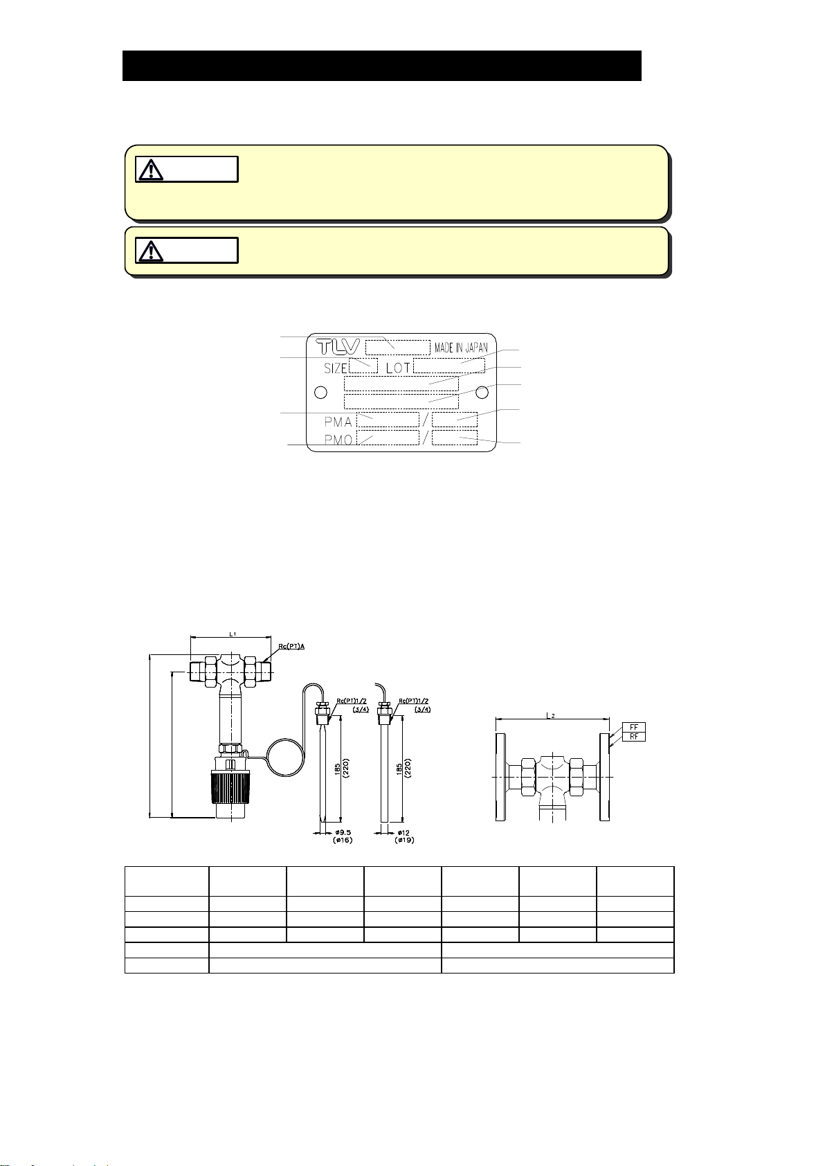
(3) INSTALL TEMPERATURE SENSOR
a) The temperature control sensor can be installed practically
anywhere. However, care should be taken to choose a place in
which the sensor will be fully immersed in the medium. The sensor
will not perform properly if it is installed in a place where it is likely
to overheat (i.e., near a heat source), or where it will be idle for
considerable periods due to the lack of flow of the medium.
b) A 15 mm female threaded socket (for nominal diameters 15 to 25
mm) or a 20 mm female threaded socket (for nominal diameters 32
to 50 mm) should be welded to the pipe wherever the sensor is to
be installed.
The screw thread of the sensor connecting nut should be wound
with sealing tape and attached before inserting the sensor into the
socket. Finally, the sensor should then be secured with the
clamping screw.
DO NOT try to detach the temperature sensor from the temperature regulator.
Capillary tubes should be positioned where they will not get damaged easily
and where the ambient temperature is even. Capillary tube should NOT be
allowed to come into contact with things such as steam pipes or any other hot
surfaces.
Capillary tubes should never be cut, and should always be handled carefully.
Any excess tubing should be coiled up. In cases where capillary tubes need to
be bent or coiled, the smallest permissible bending radius is 50 mm.
Care should be taken when installing the temperature sensor, as only similar
types of materials can be combined. For example, if a non-ferrous
temperature sensor is installed in a stainless steel tank, electrolytic corrosion
is likely to occur, so it will be necessary to use a stainless steel thermowell to
protect it.
A thermometer should be fitted close to the temperature sensor to ensure that
the temperature settings are correct and that the product is functioning
properly.
The temperature around the product should never be allowed to exceed
80 ºC.
TEMPERATURE REGULATION
Turn the adjustment ring and use the scale markings to adjust the temperature.
There are plus (+) and minus (-) symbols printed on the cover to indicate how to
lower and raise the temperature: turning the adjustment ring towards the plus
symbol will raise the temperature, whilst turning the ring towards the minus symbol
will lower the temperature.
A thermometer should be fixed near to the temperature sensor in order to fine-tune
the set point temperature.
CAUTION

172-65142M-04 (TC8) 11 Oct 2021
8
Correlation between scale markings and set temperature
Set Point Range (ºC)
Set Point Change Per
Revolution
Sensor Diameter
(mm)
0 to 35
2.5
9.5
2
16
25 to 70
3
9.5
2
16
40 to 100
4
9.5
3
16
50 to 120
4
9.5
4.5
16
70 to 150
4.5
9.5
5
16
9.5 mm sensor
16 mm sensor

172-65142M-04 (TC8) 11 Oct 2021
9
Maintenance
Take measures to prevent people from coming into direct contact with
product outlets. Failure to do so may result in burns or other injury from
the discharge of fluids.
CAUTION
Be sure to use only the recommended components when repairing the
product, and NEVER attempt to modify the product in any way. Failure to
observe these precautions may result in damage to the product or burns
or other injury due to malfunction or the discharge of fluids.
CAUTION
Operation check
If this product gets damaged in any way, it may be less efficient, and as a result
there may be a reduction in product quality and in productivity.
Periodically (at least biannually) the operation should also be checked by using
diagnostic equipment such as a stethoscope or thermometer.
Normal
OPEN VALVE: when the temperature falls below the set point,
steam flows
CLOSED VALVE: when the temperature reaches the set point, the
steam supply stops
Blocked
(Discharge
Impossible)
Although the set point temperature has been reached, the valve
does not close completely, and steam leaks from the valve seat.
Depending on the degree of leakage, there may be a slight, but
continuous flow noise. (The temperature gradually rises above the
set point temperature).
Blowing
Although the set point temperature has been reached, the valve
does not close, and steam continues to flow. A loud, continuous flow
noise can be heard. (Temperature considerably in excess of the set
point temperature.)

172-65142M-04 (TC8) 11 Oct 2021
10
Disassembly/Reassembly
When disassembling or removing the product, wait until the internal
pressure equals atmospheric pressure and the surface of the product
has cooled to room temperature. Disassembling or removing the
product when it is hot or under pressure may lead to discharge of fluids,
causing burns, other injuries or damage.
CAUTION
Use the following procedures to remove components. Use the same procedures
in reverse to reassemble.
(Installation, inspection, maintenance, repairs, disassembly, adjustment and valve
opening/closing should be carried out only by trained maintenance personnel.)
Disassembly and Reassembly of Components
Part
Disassembly
Reassembly
Regulating
thermostat
A spanner should be used to loosen
the union nut attached to the
regulating thermostat and remove it
from the valve body.
The nutshould be screwed on by
hand and tightened with a spanner.
(Tightening torque: 30 N·m)
Insulation
pipe
Use a pipe wrench to remove the
insulation pipe from the valve body.
The wrench should only be
necessary to loosen the pipe, after
which it should be possible to
unscrew it byhand.
A fluorine resin gasket should be
inserted into the groove around the
end of the insulation pipe to stop
leakage. The pipe should then be
screwed on by hand and tightened
with a pipe wrench.
Main valve
unit
A 19 mm hexagonaljig* should be
used to unscrew the main valve unit.
The valve and the screw-fitting can
then beremoved together as a single
unit.
The valveunit should be screwed on
byhand and tightened using a 19 mm
hexagonal jig*.
* can be ordered separately from TLV
Exploded View

172-65142M-04 (TC8) 11 Oct 2021
11
Troubleshooting
When disassembling or removing the product, wait until the internal
pressure equals atmospheric pressure and the surface of the product
has cooled to room temperature. Disassembling or removing the
product when it is hot or under pressure may lead to discharge of fluids,
causing burns, other injuries or damage.
CAUTION
This product is shipped after stringent checks and inspection, and should perform
its intended function for a long period of time without failure. However, should
there be any problems encountered in the operation of the product, consult the
troubleshooting guide below.
Problem
Cause
Inspection area
Remedy
The temperature
rises above the set
point
the seal is clogged
with dirt/scale
valve, valve seat
clean the valve or
the valve seat
replace the valve
body or the main
valve unit
the seal is worn
valve, valve seat
the thermostat is
damaged
temperature sensor,
capillary tube,
temperature
adjustment ring
replace the
temperature
regulation
thermostat
The temperature
does not reach the
set point
the inlet valve is
closed
inlet valve
open the inlet valve
the strainer is
clogged with dirt
strainer screen
clean the screen

172-65142M-04 (TC8) 11 Oct 2021
12
TLV EXPRESS LIMITED WARRANTY
Subject to the limitations set forth below, TLV CO., LTD., a Japanese corporation
(“TLV”), warrants that products which are sold by it, TLV International Inc. (“TII”)
or one of its group companies excluding TLV Corporation (a corporation of the
United States of America), (hereinafter the “Products”) are designed and
manufactured by TLV, conform to the specifications published by TLV for the
corresponding part numbers (the “Specifications”) and are free from defective
workmanship and materials. The party from whom the Products were purchased
shall be known hereinafter as the “Seller”. With regard to products or components
manufactured by unrelated third parties (the “Components”), TLV provides no
warranty other than the warranty from the third party manufacturer(s), if any.
Exceptions to Warranty
This warranty does not cover defects or failures caused by:
1. improper shipping, installation, use, handling, etc., by persons other than
TLV, TII or TLV group company personnel, or service representatives
authorized by TLV; or
2. dirt, scale or rust, etc.; or
3. improper disassembly and reassembly, or inadequate inspection and
maintenance by persons other than TLV or TLV group company personnel, or
service representatives authorized by TLV; or
4. disasters or forces of nature or Acts of God; or
5. abuse, abnormal use, accidents or any other cause beyond the control of
TLV, TII or TLV group companies; or
6. improper storage, maintenance or repair; or
7. operation of the Products not in accordance with instructions issued with the
Products or with accepted industry practices; or
8. use for a purpose or in a manner for which the Products were not intended; or
9. use of the Products in a manner inconsistent with the Specifications; or
10. use of the Products with Hazardous Fluids (fluids other than steam, air,
water, nitrogen, carbon dioxide and inert gases (helium, neon, argon, krypton,
xenon and radon)); or
11. failure to follow the instructions contained in the TLV Instruction Manual for
the Product.
Duration of Warranty
This warranty is effective for a period of one (1) year after delivery of Products to
the first end user. Notwithstanding the foregoing, asserting a claim under this
warranty must be brought within three (3) years after the date of delivery to the
initial buyer if not sold initially to the first end user.
ANY IMPLIED WARRANTIES NOT NEGATED HEREBY WHICH MAY ARISE BY
OPERATION OF LAW, INCLUDING THE IMPLIED WARRANTIES OF
MERCHANTABILITY AND FITNESS FOR A PARTICULAR PURPOSE AND ANY
EXPRESS WARRANTIES NOT NEGATED HEREBY, ARE GIVEN SOLELY TO THE
INITIAL BUYER AND ARE LIMITED IN DURATION TO ONE (1) YEAR FROM THE DATE
OF SHIPMENT BY THE SELLER.
Exclusive Remedy
THE EXCLUSIVE REMEDY UNDER THIS WARRANTY, UNDER ANY EXPRESS
WARRANTY OR UNDER ANY IMPLIED WARRANTIES NOT NEGATED HEREBY
(INCLUDING THE IMPLIED WARRANTIES OF MERCHANTABILITY AND FITNESS FOR
A PARTICULAR PURPOSE), IS REPLACEMENT; PROVIDED: (a) THE CLAIMED
DEFECT IS REPORTED TO THE SELLER IN WRITING WITHIN THE WARRANTY
PERIOD, INCLUDING A DETAILED WRITTEN DESCRIPTION OF THE CLAIMED

172-65142M-04 (TC8) 11 Oct 2021
13
DEFECT AND HOW AND WHEN THE CLAIMED DEFECTIVE PRODUCT WAS USED;
AND (b) THE CLAIMED DEFECTIVE PRODUCT AND A COPY OF THE PURCHASE
INVOICE IS RETURNED TO THE SELLER, FREIGHT AND TRANSPORTATION COSTS
PREPAID, UNDER A RETURN MATERIAL AUTHORIZATION AND TRACKING NUMBER
ISSUED BY THE SELLER. ALL LABOR COSTS, SHIPPING COSTS, AND
TRANSPORTATION COSTS ASSOCIATED WITH THE RETURN OR REPLACEMENT OF
THE CLAIMED DEFECTIVE PRODUCT ARE SOLELY THE RESPONSIBILITY OF BUYER
OR THE FIRST END USER. THE SELLER RESERVES THE RIGHT TO INSPECT ON
THE FIRST END USER’S SITE ANY PRODUCTS CLAIMED TO BE DEFECTIVE BEFORE
ISSUING A RETURN MATERIAL AUTHORIZATION. SHOULD SUCH INSPECTION
REVEAL, IN THE SELLER’S REASONABLE DISCRETION, THAT THE CLAIMED
DEFECT IS NOT COVERED BY THIS WARRANTY, THE PARTY ASSERTING THIS
WARRANTY SHALL PAY THE SELLER FOR THE TIME AND EXPENSES RELATED TO
SUCH ON-SITE INSPECTION.
Exclusion of Consequential and Incidental Damages
IT IS SPECIFICALLY ACKNOWLEDGED THAT THIS WARRANTY, ANY OTHER
EXPRESS WARRANTY NOT NEGATED HEREBY, AND ANY IMPLIED WARRANTY NOT
NEGATED HEREBY, INCLUDING THE IMPLIED WARRANTIES OF MERCHANTABILITY
AND FITNESS FOR A PARTICULAR PURPOSE, DO NOT COVER, AND NEITHER TLV,
TII NOR ITS TLV GROUP COMPANIES WILL IN ANY EVENT BE LIABLE FOR,
INCIDENTAL OR CONSEQUENTIAL DAMAGES, INCLUDING, BUT NOT LIMITED TO
LOST PROFITS, THE COST OF DISASSEMBLY AND SHIPMENT OF THE DEFECTIVE
PRODUCT, INJURY TO OTHER PROPERTY, DAMAGE TO BUYER’S OR THE FIRST
END USER’S PRODUCT, DAMAGE TO BUYER’S OR THE FIRST END USER’S
PROCESSES, LOSS OF USE, OR OTHER COMMERCIAL LOSSES. WHERE, DUE TO
OPERATION OF LAW, CONSEQUENTIAL AND INCIDENTAL DAMAGES UNDER THIS
WARRANTY, UNDER ANY OTHER EXPRESS WARRANTY NOT NEGATED HEREBY
OR UNDER ANY IMPLIED WARRANTY NOT NEGATED HEREBY (INCLUDING THE
IMPLIED WARRANTIES OF MERCHANTABILITY AND FITNESS FOR A PARTICULAR
PURPOSE) CANNOT BE EXCLUDED, SUCH DAMAGES ARE EXPRESSLY LIMITED IN
AMOUNT TO THE PURCHASE PRICE OF THE DEFECTIVE PRODUCT. THIS
EXCLUSION OF CONSEQUENTIAL AND INCIDENTAL DAMAGES, AND THE
PROVISION OF THIS WARRANTY LIMITING REMEDIES HEREUNDER TO
REPLACEMENT, ARE INDEPENDENT PROVISIONS, AND ANY DETERMINATION THAT
THE LIMITATION OF REMEDIES FAILS OF ITS ESSENTIAL PURPOSE OR ANY OTHER
DETERMINATION THAT EITHER OF THE ABOVE REMEDIES IS UNENFORCEABLE,
SHALL NOT BE CONSTRUED TO MAKE THE OTHER PROVISIONS UNENFORCEABLE.
Exclusion of Other Warranties
THIS WARRANTY IS IN LIEU OF ALL OTHER WARRANTIES, EXPRESS OR IMPLIED,
AND ALL OTHER WARRANTIES, INCLUDING BUT NOT LIMITED TO THE IMPLIED
WARRANTIES OF MERCHANTABILITY AND FITNESS FOR A PARTICULAR
PURPOSE, ARE EXPRESSLY DISCLAIMED.
Severability
Any provision of this warranty which is invalid, prohibited or unenforceable in any
jurisdiction shall, as to such jurisdiction, be ineffective to the extent of such
invalidity, prohibition or unenforceability without invalidating the remaining
provisions hereof, and any such invalidity, prohibition or unenforceability in any
such jurisdiction shall not invalidate or render unenforceable such provision in any
other jurisdiction.

172-65142M-04 (TC8) 11 Oct 2021
14
Service
For Service or Technical Assistance: Contact your TLV representative or your
regional TLV office.
In Europe:
Daimler-Benz-Straße 16-18, 74915 Waibstadt, Germany
Tel:
Fax:
[49]-(0)7263-9150-0
[49]-(0)7263-9150-50
Units 7 & 8, Furlong Business Park, Bishops Cleeve, Gloucestershire GL52
8TW, U.K.
Tel:
Fax:
[44]-(0)1242-227223
[44]-(0)1242-223077
Parc d’Ariane 2, bât. C, 290 rue Ferdinand Perrier, 69800 Saint Priest,
France
Tel:
Fax:
[33]–(0)4-72482222
[33]-(0)4-72482220
In North America:
13901 South Lakes Drive, Charlotte, NC 28273-6790, U.S.A.
Tel:
Fax:
[1]-704-597-9070
[1]-704-583-1610
In Mexico and Latin America:
Av. Jesús del Monte 39-B-1001, Col. Hda. de las Palmas, Huixquilucan,
Edo. de México, 52763, Mexico
Tel:
Fax:
[52]-55-5359-7949
[52]-55-5359-7585
In Oceania:
Unit 8, 137-145 Rooks Road, Nunawading, Victoria 3131, Australia
Tel:
Fax:
[61]-(0)3-9873 5610
[61]-(0)3-9873 5010
In East Asia:
36 Kaki Bukit Place, #02-01/02, Singapore 416214
Tel:
Fax:
[65]-6747 4600
[65]-6742 0345
Room 5406, No. 103 Cao Bao Road, Shanghai, China 200233
Tel:
Fax:
[86]-(0)21-6482-8622
[86]-(0)21-6482-8623
No.16, Jalan MJ14, Taman Industri Meranti Jaya, 47120 Puchong,
Selangor, Malaysia
Tel:
Fax:
[60]-3-8065-2928
[60]-3-8065-2923
252/94 (K-L) 17th Floor, Muang Thai-Phatra Complex Tower B,
Rachadaphisek Road, Huaykwang, Bangkok 10310, Thailand
Tel:
Fax:
[66]-2-693-3799
[66]-2-693-3979
#302-1 Bundang Technopark B, 723 Pangyo-ro, Bundang, Seongnam,
Gyeonggi, 13511, Korea
Tel:
Fax:
[82]-(0)31-726-2105
[82]-(0)31-726-2195
In the Middle East:
Building 2W, No. M002, PO Box371684, Dubai Airport FreeZone,Dubai, UAE
Email:
In Other Countries:
881 Nagasuna, Noguchi, Kakogawa, Hyogo 675-8511, Japan
Tel:
Fax:
[81]-(0)79-427-1818
[81]-(0)79-425-1167
Manufacturer:
881 Nagasuna, Noguchi, Kakogawa, Hyogo 675-8511, Japan
Tel:
Fax:
[81]-(0)79-422-1122
[81]-(0)79-422-0112
Table of contents
Other TLV Control Unit manuals
Popular Control Unit manuals by other brands

Emerson
Emerson KEYSTONE F580 INSTALLATION AND REPAIR INSTRUCTIONS

BERGHOF
BERGHOF EC-COM user manual

Watts
Watts WFC-03 HCM RF 230 Quick installation guide

Texas Instruments
Texas Instruments TPS7B8401EVM user guide

NXP Semiconductors
NXP Semiconductors MC56F8013 Targeting User Guide

LG
LG V-NET ACS IO Installation & user manual