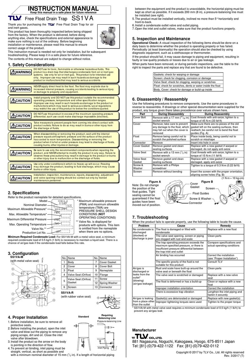
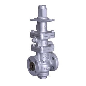
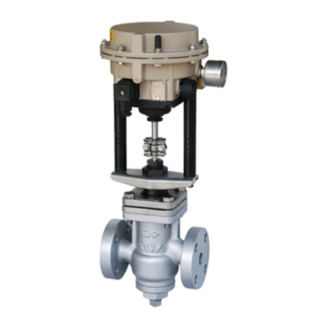
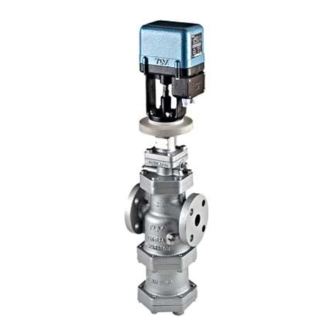
TLV CV5 User manual

172-65238M-00 (CV5)25 February 2003
Control Valve
CV5
Copyright © 2000 by TLV CO., LTD.
All rights reserve
ISO 9001/ ISO 14001
Manufacturer
Kakogawa, Japan
is approved by LRQA LTD. to ISO 9001/14001

1
Introduction
Thank you for purchasing the Control Valve
This product has been thoroughly inspected before being shipped from the
factory. When the product is delivered, before doing anything else, check the
specifications and external appearance to make sure nothing is out of the
ordinary. Also be sure to read this manual carefully before use and follow the
instructions to be sure of using the product properly.
For products with special order specifications or options, if detailed
instructions for the special order specifications or options are not contained in
this manual, please contact for full details.
This instruction manual is intended for use with the model(s) listed on the
front cover. It is necessary not only for installation but for subsequent
maintenance, disassembly/reassembly and troubleshooting. Please keep it in
a safe place for future reference.
Contents
Introduction........................................................................1
Safety Considerations.......................................................2
Specifications....................................................................4
Configuration.....................................................................5
Installation.........................................................................6
Operation...........................................................................9
Maintenance....................................................................12
Troubleshooting...............................................................14
Product Warranty ............................................................15

2
Safety Considerations
• Read this section carefully before use and be sure to follow the
instructions.
• Installation, inspection, maintenance, repairs, disassembly, adjustment,
and valve opening/closing should be carried out only by trained
maintenance personnel.
• The precautions listed in this manual are designed to ensure safety and
prevent equipment damage and personal injury. For situations that may
occur as a result of erroneous handling, three different types of cautionary
items are used to indicate the degree of urgency and the scale of potential
damage and danger: DANGER, WARNING and CAUTION.
• The three types of cautionary items above are very important for safety:
be sure to observe all of them as they relate to installation, use,
maintenance, and repair. Furthermore, TLV accepts no responsibility for
any accidents or damage occurring as a result of failure to observe these
precautions.
Symbols
Indicates a DANGER, WARNING or CAUTION item.
DANGER
Indicates an urgent situation which poses a threat of death or
serious injury
WARNING
Indicates that there is a potential threat of death or serious injury
CAUTION
Indicates that there is a possibility of injury or equipment / product
damage
CAUTION
DO NOT use this product outside the recommended operating
pressure, temperature and other specification ranges.
Improper use may result in such hazards as damage to the product or
malfunctions that may lead to serious accidents. Local regulations may
restrict the use of this product to below the conditions quoted.
Use hoisting equipment for heavy objects (weighing approximately
20 kg or more).
Failure to do so may result in back strain or other injury if the object
should fall.
Take measures to prevent people from coming into direct contact
with product outlets.
Failure to do so may result in burns or other injury from the discharge of
fluids.
When disassembling or removing the product, wait until the
internal pressure equals atmospheric pressure and the surface of
the product has cooled to room temperature.
Disassembling or removing the product when it is hot or under pressure
may lead to discharge of fluids, causing burns, other injuries or damage.
Safety considerations continued on next page.

3
CAUTION
Be sure to use only the recommended components when repairing
the product, and NEVER attempt to modify the product in any way.
Failure to observe these precautions may result in damage to the
product and burns or other injury due to malfunction or the discharge of
fluids.
Do not use excessive force when connecting threaded pipes to the
product.
Over-tightening may cause breakage leading to fluid discharge, which
may cause burns or other injury.
Use only under conditions in which no freeze-up will occur.
Freezing may damage the product, leading to fluid discharge, which
may cause burns or other injury.
Use only under conditions in which no water hammer will occur.
The impact of water hammer may damage the product,
leading to fluid
discharge, which may cause burns or other injury.

4
Specifications
DO NOT use this product outside the recommended operating pressure,
temperature and other specification ranges. Improper use may result in
such hazards as damage to the product or malfunctions which may
lead to serious accidents. Local regulations may restrict the use of this
product to below the conditions quoted.
Use only under conditions in which no freeze-up will occur. Freezing may
damage the product, leading to fluid discharge, which may cause
burns or other injury.
Valve
Model CV5
Body material Cast Iron Cast Steel
Connection Flange
Size 15
20
25
32
40
50
15
20
25
32
40
50
PMO (MPaG) 1.3 1.0
2.5 1.7
1.0
TMO (MPaG) 200 220
Seat Plug Sealing Metal Sealing
Characteristic Equal Percentage
Rangeability 50 : 1
Leakage Class (IEC534-4) ClassⅣ
Actuator
Actuator Area (cm2) 120
Fail-safe Position Air to open Air to close
Bench Range (MPa) 0.04 –0.14 0.21 –0.33
Electrical Input Signal (mA) 4 –20
Air Supply Press. (MPaG) MAX. 0.6
Transit Time for Rated Travel
Approx. 3 seconds
Hysteresis (%) <1
Protection Class IP54
Ambient Temp. Range -30 –70
Motive Medium Oil-free air, filtered 5μm
* Maximum allowable pressure (PMA) and maximum allowable temperature (TMA) are PRESSURE SHELL
DESIGN CONDITIONS, NOT OPERATING CONDITIONS.

5
Configuration
Fig. 1
No. Parts Name No. Parts Name
1Valve body 8Body Gasket
2Valve Bonnet 9Actuator Body
3Valve Seat 10 Diaphragm
4Plug and Stem 11 Actuator Stem
5Guide Bushing 12 Positioner Case
6Stuffing Box V-ring 13 Stem Bracket
7Stuffing Box Spring 14 Yoke
9
10
12
14
13
6
7
2
8
4
3
1
11
5

6
Installation DO NOT use this product outside the recommended operating pressure,
temperature and other specification ranges. Improper use may result in
such hazards as damage to the product or malfunctions which may
lead to serious accidents. Local regulations may restrict the use of this
product to below the conditions quoted.
Use hoisting equipment for heavy objects (weighing approximately
20 kg or more). Failure to do so may result in back strain or other injury if
the object should fall.
Take measures to prevent people from coming into direct contact with
product outlets. Failure to do so may result in burns or other injury from the
discharge of fluids.
Do not use excessive force when connecting threaded pipes to the
product. Over-
tightening may cause breakage leading to fluid discharge,
which may cause burns or other injury.
Installation, inspection, maintenance, repairs, disassembly, and adjustment should
be done only by trained maintenance personnel.
1. Mounting position
The valve can be mounted in any position. However, strictly observe the limitations
resulting from the type of actuator used.
The valve must be installed free of stress. If necessary, support the pipelines near
the connections.
Do not install supports on the valve or on the actuator!
Thoroughly flush the pipeline prior to installation of the valve!
2. Strainer, bypass
We recommend that you install a Strainer upstream of the valve. We also
recommend that you install a shut-off valve both upstream of the strainer and
downstream of the control valve as well as a bypass line so that the plant need not
be shut down for maintenance routines.

7
3. Mounting preparations
Before attaching the actuator to the valve bonnet, actuators with close fail-safe
action "Air to open" must be pressurized to slightly retract the actuator stem.
Should no electric control signal be available during the mounting procedure, the
hexagon nut (5) must be tightened (use a hexagonal wrench SW 36) to hold the pre-
tensioned springs.
Actuators with open fail-safe action "Air to close" require to be pressurized only
for attaching the stem connector. The top diaphragm chamber must be pressurized
to approach the plug and actuator stem until they contact one another.
For electropneumatic actuators, a signal pressure can be applied to the pressure
gauge connection, however, the plug (2, Fig. 2) must be removed first.
3.1 Mounting the actuator on the valve
1) For the electropneumatic actuator, apply a pressure of approx. 3 bar to the
connection "Supply" and additionally connect a control signal of 10 mA to retract
the actuator stem.
2) Remove the hexagon nut (5) from the valve bonnet and place the actuator with
its stem retracted on the valve bonnet.
3) Make sure that the actuator is in the proper position and secure with the
hexagon nut (SW 36), applying a tightening torque of min.150 Nm.
4) Pull up the plug stem until it contacts the actuator stem.
5) Attach the stem connector pieces to each stem and screw tight with the
fastening screws.
Fig. 2 1
2
2
3
4
1
5
6
1. Zero adjuster
2. Plug (Press. gauge)
3. Electrical connector
4. Cover plate
(span and tight-
closing
function)
5. Nut
6. Vent plug
Air to close type
Air to open type

8
In case you need to deactivate the control valve action, deactivation
may only be carried out by switching off the electric control signal, do not
disconnect the supply air!
3.2Pneumatic connections
The electropneumatic actuator has tapped holes with G1/4 thread.
The customary male connections for metal pipes or plastic hoses can be used.
Connect the supply air to the "Supply" connection.
The required supply pressure is on the name plate.
Important: Supply air must always be dry, oil-and dust free. Thoroughly flush the
air pipes prior to installation.
3.3Electrical connection
1) Unthread the fastening screw of the plug connector and remove the plug
connector (3, fig.2) from the female connector on the actuator housing.
Note: Do not remove the female connector from the actuator housing. Correct
ground connection can only be guaranteed when it is in its original position.
2) Unthread the fastening screw of the plug connector and remove the rubber
gasket.
3) Lever the plug insert out of the plug connector case using a screw driver.
4) Connect the wires transmitting the control signal via the PG screw joint of the
plug connector case to the terminals of the insert which are marked 1 + , 2 –and to
its ground terminal. Secure them with screws.
5) Re-install the insert in the plug connector case. Be sure that the Pg screw joint
points to the desired direction (the plug connector case can be turned by 90°
around the insert to point to all four directions).
6) Put on the rubber gasket.
7) Plug the plug connector back in the actuator housing and secure with fastening
screw.
Fig. 3

9
Operation
DO NOT use this product outside the recommended operating pressure,
temperature and other specification ranges. Improper use may result in
such hazards as damage to the product or malfunctions which may lead
to serious accidents. Local regulations may restrict the use of this product
to below the conditions quoted.
Take measures to prevent people from coming into direct contact with
product outlets. Failure to do so may result in burns or other injury from
the discharge of fluids.
Installation, inspection, maintenance, repairs, disassembly, and adjustment should
be done only by trained maintenance personnel.
1. Checking and adjusting zero and span in electropneumatic actuators
Adjustment may only be carried out when the actuator is mounted on the valve!
Zero and span are adjusted to determine the starting point and the upper range
value of the actuator.
When the control signal (reference variable) changes from 4 to 20 mA, the valve
must correspondingly pass through its entire travel range from 0 to 100 %.
Zero adjustment is always based on the closed position of the control valve.
Actuator with close fail-safe action "Air to open", zero (starting point) must be
adjusted to 4 mA and the upper range value to 20 mA.
Whereas a globe valve assuming an open fail-safe position (Air to close), requires
adjustment to be the other way round. That is, zero must be adjusted to 20 mA and
the upper range value to 4 mA.
Zero and span of the electropneumatic actuator are adjusted to rated travel by the
manufacturer.
Air to open type
Air to close type
Fig. 4
Potentiometer for span (1)
Protective cap
Zero adjuster (4)
Jumper (2)
Cover plate (3)
Zero adjuster (4)

10
We recommend, nevertheless, that you check zero after the actuator has been
attached to the valve. Proceed as described below:
1) Connect an ammeter to the control signal input and apply compressed air to the
input "Supply".
2) Loosen the fastening screw and move away the cover plate (3, fig.4).
3) Pull the jumper from the pins to deactivate the tight-closing function.
Zero is adjusted via the zero adjuster (4, fig.4)and the upper range value via the
potentiometer for span (1, fig.4).
Important: Each modification of span results in zero shift. Zero must therefore
always be corrected after the span has been modified.
1.1 Adjusting actuators with close fail-safe action "Air to open"
Zero (starting point)
1) Use an ammeter to adjust the input signal to 4 mA.
2) Turn the zero adjuster (4, fig.4) until the plug stem just begins to leave its rest
position.
3) Switch off the input signal and then slowly increase it again. Check if the plug
stem begins to move at 4 (+0.1) mA.
4) Correct any deviations via the zero adjuster (4, fig.4).
Turning counterclockwise causes the valve to leave its rest position earlier,
whereas turning clockwise causes the valve to delay leaving of the rest position.
Upper range value
5) Having completed adjustment of the starting point, use the ammeter to increase
the input signal to 20 mA.
When reaching the upper range value of 20 (-0.1) mA, the plug stem must have
passed through its entire rated travel range of 100 %.
6) Adjust the potentiometer for span (1, fig.4)until the upper range value is correct.
Turning clockwise increases the travel, and turning counterclockwise reduces the
travel.
7) When the correction procedure is finished, switch off the input signal and slowly
increase it again.
First check the starting point (4 mA), afterwards the upper range value (20 mA).
8)Repeat the correction procedure until both values are correct.
9) Plug the jumper on the pins so that the tightclosing function will be activated.

11
3.2 Adjusting actuators with open fail-safe action "Air to close"
Zero (starting point)
1) Use an ammeter to adjust the input signal to 20 mA.
2) Remove the cover plate and turn the zero adjuster (4, fig.4) until the plug stem
just begins to leave its rest position.
3) Increase the input signal and slowly reduce it again to 20 mA. Check if the plug
stem begins to move at 20 mA.
4) Correct any deviations via the zero adjuster (4, fig.4).
Turning counterclockwise causes the valve to leave its rest position with delay,
whereas turning clockwise causes the valve to leave earlier.
Upper range value
5) Having completed adjustment of the starting point, use the ammeter to adjust
the input signal to 4 mA.
When reaching the upper range value of 4 mA, the plug stem must have passed
through its entire rated travel range of 100 %.
6) Adjust the potentiometer for span (1, fig.4)until the upper range value is correct.
Turning clockwise increases the travel, and turning counterclockwise reduces the
travel.
7) When the correction procedure is finished, increase the input signal again.
First check the starting point (20 mA), afterwards the upper range value (4 mA).
8) Put the cover plate back over the zero adjuster.
9) Plug the jumper on the pins to activate the tight-closing function.

12
Maintenance
Take measures to prevent people from coming into direct contact with
product outlets. Failure to do so may result in burns or other injury from
the discharge of fluids.
Be sure to use only the recommended components when repairing the
product, and NEVER attempt to modify the product in any way. Failure to
observe these precautions may result in damage to the product or burns
or other injury due to malfunction or the discharge of fluids.
Use hoisting equipment for heavy objects (weighing approximately
20 kg or more). Failure to do so may result in back strain or other injury if
the object should fall.
When disassembling or removing the product, wait until the internal
pressure equals atmospheric pressure and the surface of the product has
cooled to room temperature. Disassembling or removing the product
when it is ho
t or under pressure may lead to discharge of fluids, causing
burns, other injuries or damage.
Use the following procedures to remove components. Use the same procedures in
reverse to reassemble. (Installation, inspection, maintenance, repairs, disassembly,
and adjustment should be done only by trained maintenance personnel.)
Tightening torques
Valve Size (DN) 15-25 32-50
Seat (2) (±10%) M32x1.5 170 Nm M58x1.5 500 Nm
Body nuts (1.1) (±10%) M10 10 Nm M12 30 Nm
1.Valve body
1.1.Nuts
1.2.Gasket
2.Seat
3.Plug
4.1.Spring
4.2.Packing
4.3.Washer
5.Valve bonnet
5.1.Flange
5.2.Threaded bushing
6.Nut
7.Stem connector
8.1. Actuator stem
8.2. Rod-type yoke
Fig. 5

13
1. Replacing seat and plug
If the valve does not properly seal, dirt or damagedsealing edges could be the
cause. In case of dirt, thoroughly clean the parts. In case of damaged sealing
edges, replace for new ones.
1.1Plug
When replacing the plug, you should also replace the packing (4.2, fig.5) and the
gasket (1.2, fig.5). To exchange the plug, carry out the same steps as described in
chapter 4.1. However, install a new plug instead of the used one. Apply lubricant to
the plug stem prior to installation.
1.2Seat
Replace the seat (2, fig.5) as described below:
1) Unscrew the nuts (1.1, fig.5) and lift the valve bonnet (5, fig.5) and flange (5.1,
fig.5) off the valve body (1, fig.5).
2) Unscrew the seat (2, fig.5) using the appropriate seat wrench (see torque table).
3) Apply lubricant to the thread and the sealing conus of the new seat and screw in.
4) Place the valve bonnet with flange on the valve body and secure with nuts (1.1).
Observe the tightening torques!
2. Replacing the packing
Fig. 6 If the valve leaks at the stuffing box, the packing (4.2)
of the stuffing box needs to be exchanged as follows:
1) Unscrew the nuts (1.1) and remove the valve bonnet
(5) and flange (5.1).
2) Check the gasket (1.2) in the valve body for damage.
We recommend that you re-place the gasket.
3) Screw off the threaded bushing (5.2) and pull out the
plug (3).
4) Pull out the damaged packing (4.2) using an
appropriate tool. Remove the washer (4.3) and spring
(4.1) and clean the packing chamber.
5) Apply lubricant to the individual parts of the new packing and the plug stem. Insert
the plug (3) in the valve bonnet (5).
6) Place the valve bonnet with flange on the valve body and secure with nuts (1.1).
Observe the tightening torques given in the table.
7) Insert the spring (4.1) and washer (4.3) and carefully slide the new packing (4.2)
over the plug stem into the packing chamber. Screw in the threaded bushing (5.2)
and tighten.
4.2
4.3
5
5.3
4.1

14
Troubleshooting
When disassembling or removing the product, wait until the internal
pressure equals atmospheric pressure and the surface of the product has
cooled to room temperature. Disassembling or removing the product
when it is hot or under pressure may lead to discharge of fluids, causing
burns, other injuries or damage.
Installation, inspection, maintenance, repairs, disassembly, and adjustment should
be done only by trained maintenance personnel.
When the product fails to operate properly, use the following table to locate and
remedy the cause.
Problem Cause Remedy
Air supply press. might be too
high (Air to open type)
Readjust the air supply press.
Air supply press. might be too
low (Air to close type)
Readjust the air supply press.
Zero point might be moved Readjust the zero point
Primary press. of control
valve might be too high
Check the system
Plug or valve seat might be
worn or dirty
Clean parts or replace
Bypass shut-off valve might
be leaking
Check the shut-off valve
Valve Leak
Plug stem can not move
smoothly
Replace parts or reassemble
the bonnet
External leakage from
stuffing box
V-ring or stem might be worn
or dirty
Clean parts or replace
Hunting or chattering of the
valve
Signal from the controller
might be not good
Check the controller
(especially PID)
Diaphragm might be
deformed or broken Replace the partsCan not open or close form
proper point Air supply press. might be too
low Readjust the air supply press.
Signal from the controller
might be not good Check the controller and
signal line
No air supply Check the air supply
No operate at all
Supplied air might contain
dust, water, or oil Replace the actuator unit and
install better air filer and dryer
CAUTION
The control valve is not shut-off valve, therefore it cannot always shut-
off completely.

15
Product Warranty
Warranty Period
One year following product delivery.
1. Warranty Coverage
TLV CO., LTD. warrants this product to the original purchaser to be free from defective
materials and workmanship. Under this warranty, the product will be repaired or
replaced at our option, without charge for parts or labor.
2. This product warranty will not apply to cosmetic defects, nor to any product whose
exterior has been damaged or defaced; nor does it apply in the following cases:
•Malfunctions due to improper installation, use, handling, etc., by other than TLV
CO., LTD. authorized service representatives.
•Malfunctions due to dirt, scale, rust, etc.
•Malfunctions due to improper disassembly and reassembly, or inadequate
inspection and maintenance by other TLV CO., LTD. authorized service
representatives.
•Malfunctions due to disasters or forces of nature.
•Accidents or malfunctions due to any other cause beyond the control of TLV
CO., LTD.
Under no circumstances will TLV CO., LTD. be liable for consequential economic loss
damage or consequential damage to property.
* * * * * * *
For Service or Technical Assistance:
Contact your representative or your regional office.
Manufacturer
CO., LTD.
881 Nagasuna, Noguchi
Kakogawa, Hyogo 675-8511 JAPAN
Tel: 81-(0)794 -27 -1800
Table of contents
Other TLV Control Unit manuals
Popular Control Unit manuals by other brands
Leonard
Leonard TM-2020A INSTALLATION ADJUSTMENT SERVICE
Texas Instruments
Texas Instruments TPS54362B EVM user guide
Azbil
Azbil ACTIVAL VY519 J Series Specifications & instructions
Potter
Potter PAD100-LEDK installation manual
Red Valve
Red Valve TIdeFlex 37 Series Installation, operation and maintenance manual
Bristan
Bristan N2 SHCDIV G Installation instructions and user guide


