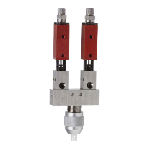
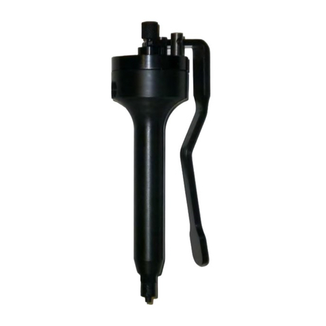
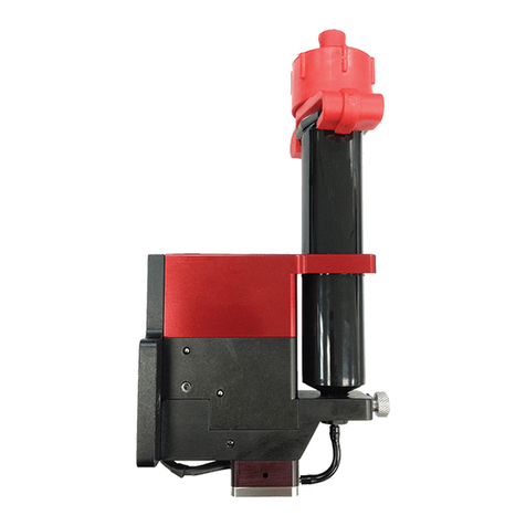
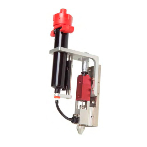
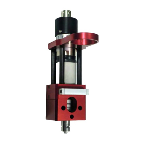
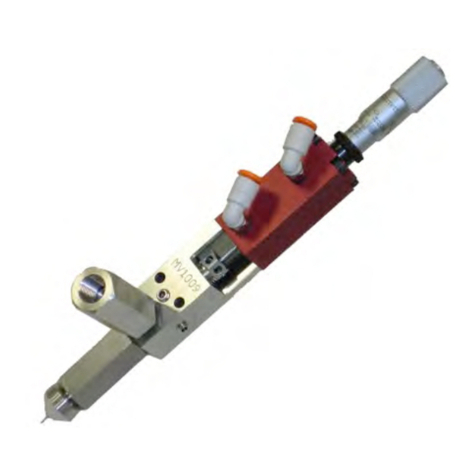
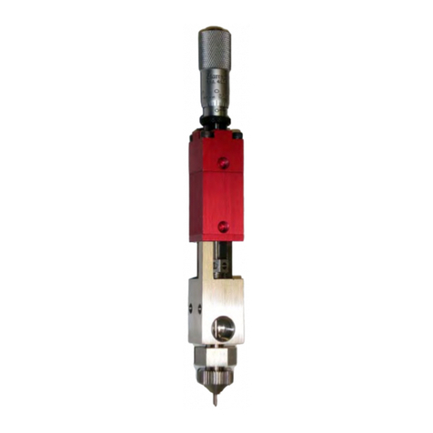
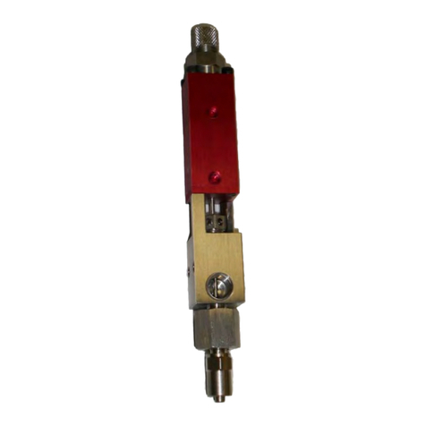
PVA PC200 Series User manual

Precision Valve & Automation
One Mustang Drive
Cohoes, NY 12047
www.pva.net
PC200 Valve Series
OWNER’S MANUAL
Rev G
WHERE
PRECISION
DRIVES
PRODUCTION

PC200
PVA
Revision G(2019)
2 of 56
This document is based on information available at the time of its publication. While
efforts have been made to ensure the contents of this manual are accurate, the
information contained herein does not purport to cover all specific details or variations
in hardware, or to provide for every possible contingency in connection with
installation, operation, or maintenance. Features may be described herein which are
not present in all hardware and software systems. Precision Valve and Automation, Inc.
assumes no obligation of notice to holders of this document with respect to changes
subsequently made.
Precision Valve and Automation, Inc. makes no representation or warranty, expressed,
implied, or statutory with respect to, and assumes no responsibility for the accuracy,
completeness, sufficiency, or usefulness of the information contained herein. No
warranties of merchantability or fitness for purpose shall apply.
This document, including the information contained herein, is the property of
Precision Valve and Automation, Inc. and is considered confidential and
proprietary information. It is delivered on the express condition that it not be
used, disclosed, or reproduced, in whole or in part, for any reason without prior
written consent of Precision Valve and Automation, Inc.
Copyright © 2019
Precision Valve and Automation, Inc.
All Rights Reserved.

PC200
PVA
Revision G(2019)
3 of 56
Table of Contents
1. Introduction ............................................................................................. 5
Document History ............................................................................................... 5
Safety .................................................................................................................. 6
Theory of Operation............................................................................................ 7
Air Section ...................................................................................................7
Fluid Section................................................................................................7
Pneumatic Schematic.......................................................................................... 7
Personal Protective Equipment .......................................................................... 8
Waste Disposal.................................................................................................... 8
Tool Kit ................................................................................................................ 8
Overview.................................................................................................. 9
Valve Operation ..................................................................................... 10
Startup .............................................................................................................. 10
Install the Static Mixer ...................................................................................... 11
Shutdown.......................................................................................................... 13
Maintenance .......................................................................................... 13
Disassemble the Valve ...................................................................................... 14
Procedure.................................................................................................. 14
Clean the Disassembled Valve .......................................................................... 21
Assemble the Valve........................................................................................... 23
Procedure.................................................................................................. 23
With a Press ..............................................................................................28
To Engage by Hand:...................................................................................29
Periodic Maintenance............................................................................. 33
How to Replace a Static Mixer.......................................................................... 33
How to Replace Lip Seals .................................................................................. 33
Seal Plate Lip Seals ....................................................................................33
Fluid Section Lip Seals ............................................................................... 33

PC200
PVA
Revision G(2019)
4 of 56
How to Replace Valve Rods .............................................................................. 33
How to Replace Sleeve Bearings....................................................................... 33
How to Replace O-rings .................................................................................... 34
Piston O-ring .............................................................................................34
Fluid Section O-rings .................................................................................34
Air Cylinder O-rings ...................................................................................34
Fluid Manifold O-rings ..............................................................................34
PC200R Series Reference ........................................................................ 34
PC200R-SS Bill of Materials............................................................................... 35
PC200R-AL Bill of Materials............................................................................... 36
PC200R Series Mechanical Drawings ................................................................ 37
PC200R Series Exploded View........................................................................... 38
PC200RW Series Reference ..................................................................... 38
PC200RW-SS Bill of Materials ........................................................................... 39
PC200RW-AL Bill of Materials ........................................................................... 40
PC200RW Series Mechanical Drawings ............................................................ 41
PC200RW Series Exploded View ....................................................................... 42
How to Order ......................................................................................... 43
Accessories and Options ................................................................................... 44
Spare Parts ............................................................................................. 46
Spare Parts Kits ................................................................................................. 46
Technical Specifications .......................................................................... 50
Troubleshooting ..................................................................................... 51
Notes ..................................................................................................... 53
Warranty................................................................................................ 54
Table of Figures ...................................................................................... 55

PC200
PVA
Revision G(2019)
5 of 56
1. Introduction
Before you operate this system, read the operation and setup manual. This will help you
to become familiar with the product and ensure successful operation.
If any questions or problems arise, contact PVA’s Customer Service Department for
support.
PVA Contact Information
Main Office PVA
One Mustang Drive
Cohoes, NY 12047
Tel +1-518-371-2684
Fax +1-518-371-2688
Website http://www.pva.net
Email mailto: info@pva.net
Technical Support
Tel +1-518-371-2684
Document History
Revision
Revision Date
Reason for Changes
Revision G
March 2019
Part Number Updated
Revision F
February 2016
Initial Release of New Template
NOTE: All photographs and CAD model representations in this document are a
“general representation” of the valve and its components. The actual
appearance of the valve and its components can differ based upon customer
specific configuration.

PC200
PVA
Revision G(2019)
6 of 56
Safety
Certain warning symbols are affixed to the machine and correspond to notations in this
manual. Before operating the system, identify these warning labels and read the
notices described below. Not all labels may be used on any specific system.
Always wear approved safety glasses when you operate or
work near the workcell.
Before you operate the system, read and understand the
manuals provided with the unit.
Never put hands or tools in areas with this symbol when the
machine is in operation. A dangerous condition may exist.
Read and understand the manuals provided with the unit
before any repairs or maintenance is done. Only a qualified
individual should do service.
Use caution when there are pressurized vessels. Find and
repair any leaks immediately. Always wear appropriate safety
equipment when you work with pressurized vessels or vessels
that contain chemicals.
Shear hazard from moving parts. Avoid contact.

PC200
PVA
Revision G(2019)
7 of 56
Theory of Operation
The PC200 is a rear closing, two component dispensing valve. Applications include
potting, bead placement, and gaskets where a low to medium flow rate is required. This
valve has adjustable snuff back to prevent drips or strings at the end of the static mixer.
Part A and part B materials flow into the valve separately and out of the valve separately
into a disposable static mixer. It is not necessary to disassemble and clean the valve at
the end of each day. The PC200 has a divorced design made of two major sections: the
air section and the fluid section
Air Section
The air section is an aluminum body with a simple piston/cylinder combination used to
open and close the valve. The stroke adjustment screw in the upper air body controls
how far the piston and rod assembly can retract and controls snuff back.
Fluid Section
The fluid section is available in two materials:
•Stainless steel
•Aluminum (decreased weight for handheld applications)
The fluid section includes two rods with lip seals on each side of the valve to control
fluid flow of part A and part B. Fluid dispenses as the rods move to the forward position
past the lip seals. When the rods retract back into the lip seals the fluid flow stops and
creates a snuff back action on the fluid.
Pneumatic Schematic
Figure 1: General PC200 Pneumatic Schematic

PC200
PVA
Revision G(2019)
8 of 56
Personal Protective Equipment
Operators must use eye protection because material contents are under pressure.
Always wear gloves when handling materials and solvents. Refer to MSDS sheets on the
material being dispensed for other precautions.
Waste Disposal
Dispose of all used parts and materials in accordance with local laws and regulations.
Tool Kit
PVA offers tool kits for dispense valves. The tool kit for the PC200 series valve is part
number B12-2602. This includes all necessary tools and lubricant to do maintenance on
this valve.
Table 1: B12-2602 Contents List
Qty
Part Number
Description
1
0266244
8” Adjustable Wrench
1
7122A47
3/16” Hex Key
2
26571
5/32” Hex Key
2
7122A44
1/8” Hex Key
2
7122A43
7/64” Hex Key
1
56945A13
3/16” Combination Wrench
1
B62-2048
2.5cc Silicone Lubricant
1
MM115
Removable Thread Locker
1
5516A18
Tweezers
1
9570K71
Hook and Pick Set
1
214-0544
Lip Seal Alignment Tool
1
98381A636
Lip Seal Insertion Tool
1
8511T17
Tool Bag

PC200
PVA
Revision G(2019)
9 of 56
Overview
Before you operate the valve, know the valve components. Examine the valve
components shown below for safe and correct operation.
Figure 2: Valve Components

PC200
PVA
Revision G(2019)
10 of 56
Valve Operation
Startup
1. Install the valve pneumatically as shown in Section 1.5 and set the air
pressure that operates the valve between 60-100 psi.
2. Cycle the valve several times. Make sure that the valve is not pointed at
anyone.
When the valve cycles correctly, you can hear the piston hit the stroke adjustment
screw and the rods can be seen going up and down in the center.
NOTE: If the valve does not cycle correctly, refer to Section 11.
3. Connect the material delivery system to the valve. Part A material
connects on the on the left side, part B material connects on the right side.
4. Cycle the valve open to bleed. Part A and B materials should start to
flow separately out of the fluid manifold.
5. Bleed the valve until all the air is released, and the material releases
smoothly without any breaks in the flow. Any break in the flow of the
material shows there is still air in the system.
6. Bleed air from the bleed screws if necessary.
NOTE: Part A and B materials may not start to dispense from the valve at
the same time, flow depends on the necessary mix ratio.
7. Use a 3/16” hex key to adjust the stroke adjustment screw to get the
necessary amount of snuff back.
Turn the stroke adjustment screw clockwise to decrease the amount of snuff back,
or counter-clockwise to increase the amount of snuff back. If the stroke adjustment
screw is turned down too far the valve will not close and material will leak from the
manifold nozzle.
NOTE: A good general setting for snuff back is to turn the stroke
adjustment screw clockwise until material starts to leak from the valve
manifold when under pressure, then turn the stroke adjustment screw a ½
turn counter-clockwise or until it does not leak.
8. When snuff back is set, use an adjustable wrench to tighten the jam nut
against the sealing washer and cylinder cap to lock it in place.
NOTE: Refer to Section 11 for any other problems.

PC200
PVA
Revision G(2019)
11 of 56
Install the Static Mixer
1. Put the static mixer on the PC200 valve manifold as shown.
Figure 3: Static Mixer
2. Hold the static mixer on the PC200 manifold with your hand.
3. Use the purge function (in Manual mode) on the machine controller to
purge material through the static mixer.
4. Continue to purge until the static mixer is fully filled with material.
Figure 4: Fill the Static Mixer
Now the trapped air must be released from the top of the static mixer.

PC200
PVA
Revision G(2019)
12 of 56
5. Pull the static mixer straight down, off the PC200 valve manifold so there is
a small space between the static mixer and the manifold.
6. Use the purge function on the machine controller to purge material until it
overflows from the top of the static mixer. Let all air release from the top of
the static mixer.
7. Push the static mixer firmly back onto the PC200 manifold.
8. Clean the material completely off of the static mixer and PC200 valve.
Figure 5: Purge the Static Mixer
9. Put the static mixer retaining nut on and use a wrench to tighten.
10. Install the desired needle on the end of the static mixer.
11. Use the purge function on the machine controller to purge material through
the static mixer. Purge the volume of the entire static mixer to fill it with
fresh material.
12. Push and release the purge button. Examine the static mixer for drips after
the material has dispensed.
13. If it continues to drip, do steps 3-13 again. Drips from the tip of the static
mixer are caused by air that is trapped inside.
14. If the static mixer does not drip, the valve is ready to dispense.

PC200
PVA
Revision G(2019)
13 of 56
Shutdown
To keep the PC200 valve in good condition do these steps at the end of each day:
1. Remove the static mixer.
2. Purge fresh material through the valve until both material streams are
completely clean and have no cross-contamination.
3. Clean all material off of the manifold nozzle.
4. Put a night cap (PVA part number 214-3832) on the manifold nozzle.
5. Release the pressure in the system, refer to the workcell manual.
Figure 6: PC200 Night Cap
NOTE: Refer to Sections 6 and 7 for part reference numbers.
Maintenance
Interval
Action
Daily
•Examine the material outlets for contamination and cured
material.
Weekly
•Examine component A and B material containers or cartridges
for signs of cured or dried material.
Before you do maintenance on this valve, make sure you have a spare parts kit. If any
parts have wear or damage, replace them with new parts from the kit.

PC200
PVA
Revision G(2019)
14 of 56
Disassemble the Valve
This section shows how to disassemble PC200 valves (Std. PC200R process is
shown). Some steps that involve rods, lip seals, sleeve bearings, and O-rings will
differ between the R and RW series of the PC200. Not all options are shown. When
procedures are different from what is shown, “Notes” are given. If you have
questions about procedure steps, parts, or content, contact PVA’s customer service
department.
Procedure
Put valve sections, seals, parts, and screws in solvent to soak if material can be seen on
them. Do not combine materials A and B or they will cure. Examine all parts for wear
and damage. Replace parts if necessary.
1. Relieve system pressure. Disconnect material and air fittings. Disconnect the
valve from the dispense system.
2. Remove the retaining nut and the static mixer and needle.
Figure 7: PC200 Ready for Disassembly
3. Remove front bleed port plugs if necessary.
4. Use a hex key to remove the four machine screws in the fluid manifold.
Figure 8: Fluid Manifold Screws
5. Pull the manifold off of the valve assembly.

PC200
PVA
Revision G(2019)
15 of 56
Figure 9: Disassembled Fluid Manifold
6. Remove the O-rings in the fluid manifold.
7. Clean the O-rings and examine them for damage.
8. Use a hex key to remove the two shoulder bolts from the seal plate.
Figure 10: Valve Shoulder Bolts
9. Use a hex key to remove the four machine screws from the air cap.
Figure 11: Remove Air Cap Screws
10. Remove the air cap.

PC200
PVA
Revision G(2019)
16 of 56
Figure 12: Air Cylinder without Air Cap
11. Use a wrench to loosen the air fittings and then use your hand to remove
them.
Figure 13: Remove Air Fittings
12. Use a correctly sized hex key to push on the rods engaged in the seal plate.
Figure 14: Push Rods to Disengage
13. Push on the rods one at a time until the piston-rod assembly disengages
from the air cylinder.

PC200
PVA
Revision G(2019)
17 of 56
Figure 15: Disengaged Piston-Rod Assembly
14. Remove the seal plate.
Figure 16: Seal Plate Removed
15. Remove and clean the O-rings in between the seal plate and the fluid
section.
16. Remove and clean the lip seals in the fluid section.
17. Pull the piston-rod assembly out of the air cylinder.
Figure 17: Piston-Rod Assembly Removed
NOTE: RW-series PC200 uses two different size rods.

PC200
PVA
Revision G(2019)
18 of 56
18. Pull the air cylinder, separation block, and fluid section apart.
Figure 18: Disconnect Valve Sections
19. Examine the sleeve bearings in the separation block for damage or wear. If
there is any sign of wear replace them.
20. To remove the sleeve bearings, install a correctly sized tap into the sleeve
bearing in the bottom of the separation block.
Figure 19: Install the Tap into the Sleeve Bearing
21. Push the tap in and turn it clockwise to engage the tap in the sleeve bearing.
Figure 20: Engage the Tap into the Sleeve Bearing

PC200
PVA
Revision G(2019)
19 of 56
WARNING: Do not let the tap go through the sleeve bearing and into the
separation block.
22. Continue to turn the tap clockwise and push in until the sleeve bearing starts to
spin when you turn the tap.
23. Continue to turn the tap clockwise and pull out as you turn. The sleeve bearing
will start to pull out of the separation block.
Figure 21: Turn the Tap and Pull Out
24. Pull the sleeve bearing out of the separation block. Do the procedure again for
the other sleeve bearing.
Figure 22: Remove the Sleeve Bearing
25. Clean any pieces of the sleeve bearings from the separation block.
26. Use the hook and pick set to remove the lips seals and the O-rings from the
fluid section.

PC200
PVA
Revision G(2019)
20 of 56
Figure 23: Remove Lip Seals From Fluid Section
27. Clean the lip seals.
28. Use the hook and pick set to remove the O-ring in the air cylinder.
Figure 24: Air Cylinder O-ring
29. Examine and clean the O-ring.
Table of contents
Other PVA Control Unit manuals
Popular Control Unit manuals by other brands

APV
APV FS900 Series Installation, operation & maintenance manual

Emerson
Emerson CROSBY HE ISOFLEX Series INSTALLATION, MAINTENANCE AND ADJUSTMENT INSTRUCTIONS

VAT
VAT 650 Series Installation, operating, & maintenance instructions

Lauda
Lauda LRZ 918 Operation manual

Pioneer
Pioneer CU-SA004 operating instructions

MaxStream
MaxStream XStream X09-001 Series product manual