TLV Cospect MC-COS-3 User manual

172-65169MA-08 (MC-COS Multi-control Valve) 28 May 2010
High-precision Multi-control Valve for Steam
COSPECT
MC-COS-3/MC-COS-16
Actuator: MC-GA2
Copyright © 2010 by TLV CO., LTD.
All rights reserved
ISO 9001/ ISO 14001
Manufacturer
Kakogawa, Japan
is approved by LRQA LTD. to ISO 9001/14001

172-65169MA-08 (MC-COS Multi-control Valve) 28 May 2010
1
Contents
Introduction ........................................................................ 1
Safety Considerations ........................................................ 2
Specifications ..................................................................... 4
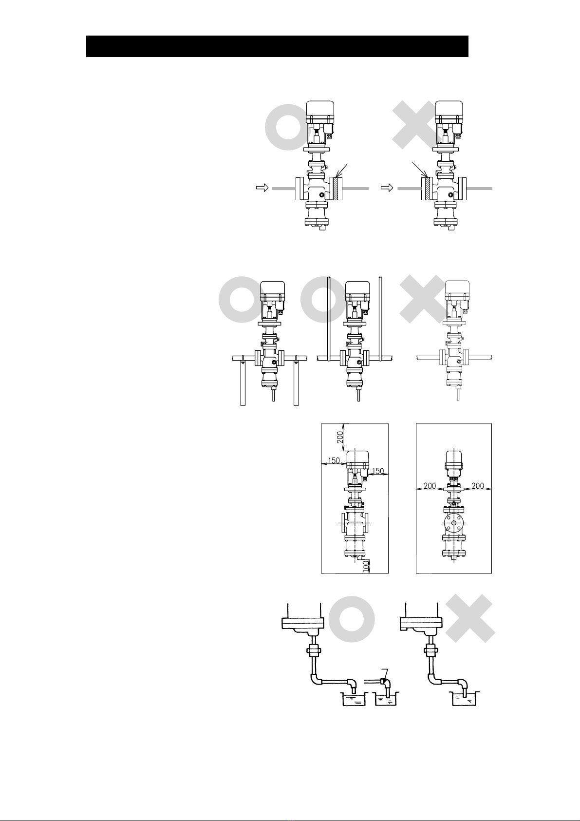
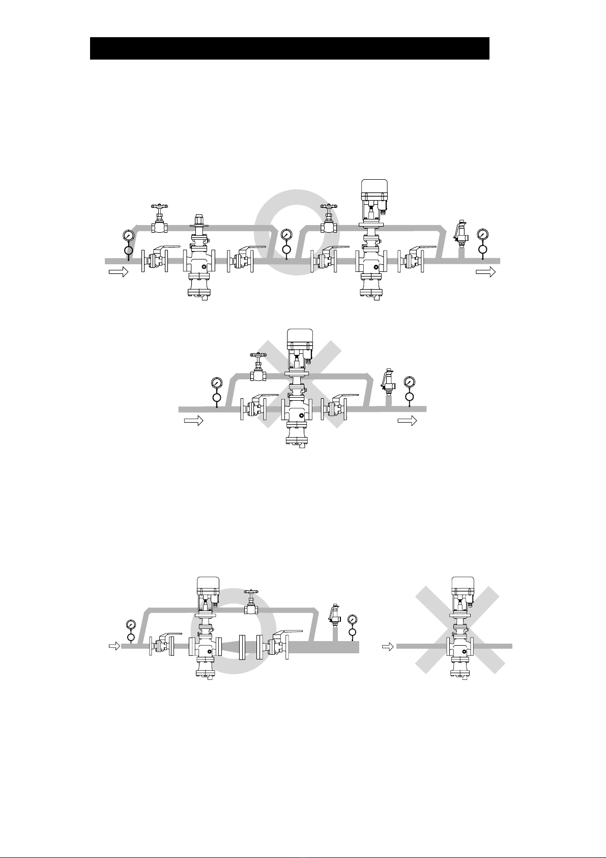
Correct Usage of the MC-COS Multi-control Valve ............ 6
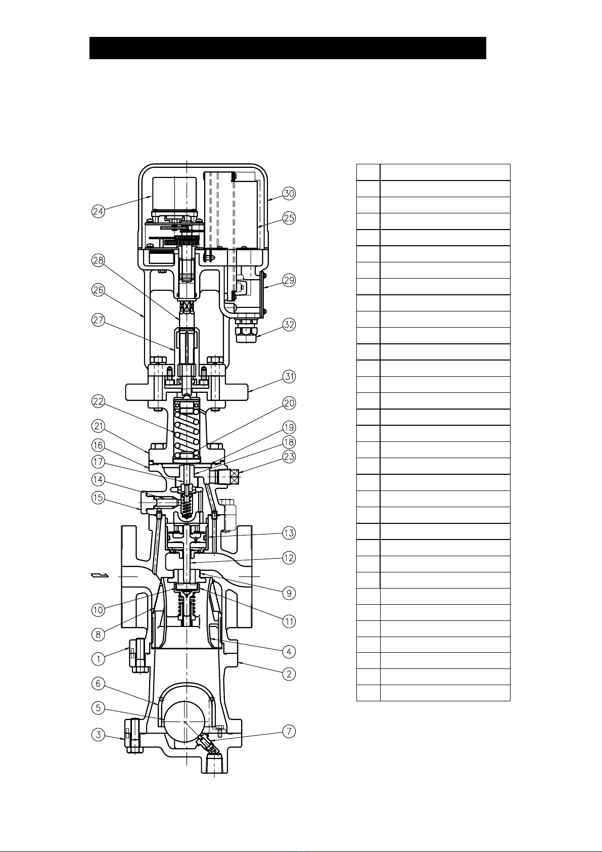
Configuration...................................................................... 8
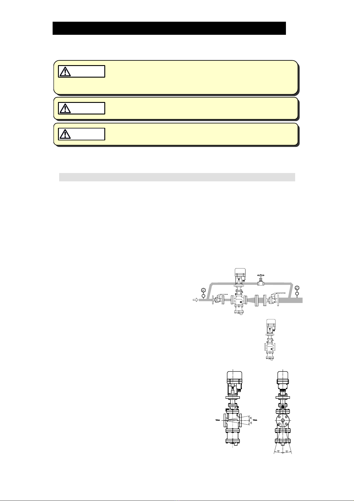
Installation ........................................................................ 10
Wiring Instructions............................................................ 17
Setting the Valve Coefficient ............................................ 19
Operation ......................................................................... 20
Inspection and Maintenance ............................................ 22
Disassembly..................................................................... 23
Reassembly ..................................................................... 29
Troubleshooting ............................................................... 30
Product Warranty ............................................................. 36
Introduction
Thank you for purchasing the MC-COS high-precision multi-control
valve for steam.
This product has been thoroughly inspected before being shipped from the
factory. When the product is delivered, before doing anything else, check the
specifications and external appearance to make sure nothing is out of the
ordinary. Also be sure to read this manual carefully before use and follow the
instructions to be sure of using the product properly.
Steam-using equipment can achieve its intended efficiency only if the steam
being used is very dry. Using steam in which matter such as condensate,
scale, types of grease or air is entrained can not only result in problems with
the steam-using equipment and in lowered productivity, but can also lead to
shortened service life for and malfunction of the multi-control valves.
The high-precision multi-control valve, model MC-COS, provides
accurate pressure control (MC-COS-3, MC-COS-16) and temperature control
(MC-COS-16) when combined with the SC-F70 digital indicator
controller or the SP-F70 programmable indicator controller.
If detailed instructions for special order specifications or options not contained
in this manual are required, please contact for full details.
This instruction manual is intended for use with the model(s) listed on the front
cover. It is needed not only for installation, but also for subsequent
maintenance, disassembly/reassembly and troubleshooting. Please keep it in
a safe place for future reference.

172-65169MA-08 (MC-COS Multi-control Valve) 28 May 2010
2
Safety Considerations
• Read this section carefully before use and be sure to follow the instructions.
• Installation, inspection, maintenance, repairs, disassembly, adjustment and valve
opening/closing should be carried out only by trained maintenance personnel.
• The precautions listed in this manual are designed to ensure safety and prevent
equipment damage and personal injury. For situations that may occur as a result of
erroneous handling, three different types of cautionary items are used to indicate
the degree of urgency and the scale of potential damage and danger: DANGER,
WARNING and CAUTION.
• The three types of cautionary items above are very important for safety: be sure to
observe all of them as they relate to installation, use, maintenance and repair.
Furthermore, TLV accepts no responsibility for any accidents or damage occurring
as a result of failure to observe these precautions.
Symbols
Indicates a DANGER, WARNING or CAUTION item.
DANGE
R
Indicates an urgent situation which poses a threat of death or
serious injury
WARNING Indicates that there is a potential threat of death or serious injury
CAUTION Indicates that there is a possibility of injury or equipment / product
damage
WARNING NEVER apply direct heat to the float.
The float may explode due to increased internal pressure, causing
accidents leading to serious injury or damage to property and
equipment.
CAUTION Install properly and DO NOT use this product outside the
recommended operating pressure, temperature and other
specification ranges.
Improper use may result in such hazards as damage to the product
or malfunctions that may lead to serious accidents. Local
regulations may restrict the use of this product to below the
conditions quoted.
DO NOT use the product in excess of the maximum operating
pressure differential.
Such use could make discharge through the steam trap impossible
(blocked).
Use hoisting equipment for heavy objects (weighing
approximately 20 kg (44 lb)or more).
Failure to do so may result in back strain or other injury if the object
should fall.
Take measures to prevent people from coming into direct
contact with product outlets.
Failure to do so may result in burns or other injury from the
discharge of fluids.
Safety considerations are continued on the next page.

172-65169MA-08 (MC-COS Multi-control Valve) 28 May 2010
3
CAUTION When disassembling or removing the product, wait until the
internal pressure equals atmospheric pressure and the surface
of the product has cooled to room temperature.
Disassembling or removing the product when it is hot or under
pressure may lead to discharge of fluids, causing burns, other
injuries or damage.
Be sure to use only the recommended components when
repairing the product, and NEVER attempt to modify the
product in any way.
Failure to observe these precautions may result in damage to the
product and burns or other injury due to malfunction or the
discharge of fluids.
Do not use excessive force when connecting threaded pipes to
the product.
Over-tightening may cause breakage leading to fluid discharge,
which may cause burns or other injury.
Use only under conditions in which no freeze-up will occur.
Freezing may damage the product, leading to fluid discharge, which
may cause burns or other injury.
Use only under conditions in which no water hammer will
occur.
The impact of water hammer may damage the product, leading to
fluid discharge, which may cause burns or other injury.
Make sure the power supply is OFF before carrying out work
on the wiring or inspections involving disassembly.
If such work is carried out with the power on, there is a danger
that equipment may malfunction or electric shock may occur,
leading to injury or other accidents.
Make sure that wiring work requiring a special license is
carried out by qualified personnel.
If carried out by unqualified personnel, overheating or short
circuits leading to injury, fires, damage or other accidents may
occur.
When using this product, NEVER stand close to, or leave tools
anywhere near moving parts, such as the shaft.
Contact with moving parts or objects becoming caught in moving
parts could lead to injury or damage or other accidents.

172-65169MA-08 (MC-COS Multi-control Valve) 28 May 2010
4
Specifications
Install properly and DO NOT use this product outside the recommended
operating pressure, temperature and other specification ranges.
Improper use may result in such hazards as damage to the product or
malfunctions which may lead to serious accidents. Local regulations
may restrict the use of this product to below the conditions quoted.
CAUTION
DO NOT use the trap in excess of the maximum operating pressure
differential; such use could make discharge impossible (blocked).
CAUTION
Use only under conditions in which no freeze-up will occur. Freezing
may damage the product, leading to fluid discharge, which may cause
burns or other injury.
CAUTION
Refer to the product nameplate for detailed specifications.
* Valve No. is displayed for products with options. This item is omitted from the nameplate when there
are no options.
Actuator Specifications
Actuator Model MC-GA2
Power Source Voltage Free between 100 and 240 V AC (50/60 Hz)
Power Consumption With motor running: 75 VA max.
Insulation Resistance 500 V DC, 100 MΩmin. between the power source
terminal and ground terminal
Power
Source
Withstand Voltage Between the power source terminal and ground terminal:
1500 V AC, 1 min. or 1800 V AC, 1 second
Drive System Positional control by DC brushless motor
Operation Input
(Valve Opening)
4 – 20 mA DC (input impedance 250 Ω)
Emergency Action Valve fully closed by an operation signal interruption.
When input power is cutoff: held at position just before
power cutoff
Time Rating Continuous
Thermal Protection Built-in overcurrent protection circuit
Time Required to Fully
Open/Close
Fully closed →fully open: Approx. 15 seconds
Operation
Manual Operation Possible with the power OFF
Allowable Ambient Temperature Range 0 to 50 °C (32 to 122 °F)
Allowable Ambient Humidity 10% to 90% RH (without dew)
Allowable altitude 2000m (6600 ft) max.
Vibration Resistance 0.5 G max.
Water Resistance Rain resistant (equivalent to IP54)
Environment
Material Motor cover: Aluminum
Main mounting plate: cast iron
Primary Pressure Range
Model
Serial Numbe
r
Nominal Diamete
r
Maximum Operating
Temperature
Valve No.*
Secondary Pressure
Adjustable Range

172-65169MA-08 (MC-COS Multi-control Valve) 28 May 2010
5
CV Value
(mm) 15 20 25 32 40 50 65 80 100
Size (in) (1/2) (3/4) (1) (11/4) (11/2) (2) (21/2) (3) (4)
Cv (US) 3.8 6.9 11.1 15.5 24.0 37.2 59.3 85.0 128
Cv (UK) 3.2 5.7 9.2 12.9 20.0 31.0 49.4 70.8 107
Kvs (DIN) 3.3 5.9 9.5 13.3 20.6 31.9 50.8 72.9 110
Acceptable Operating Range
Model MC-COS-3 MC-COS-16
Primary Pressure
Range
0.1 – 0.3 MPaG
(15 – 45 psig)
0.2 – 1.6 MPaG
(30 – 250 psig)
Secondary Pressure
Adjustable Range
(All conditions must
be met)
0.01 – 0.05 MPaG
(1.5 – 7 psig)
Within 10 – 84% of the primary pressure
(Minimum adjustable pressure of
0.03 MPaG (5 psig))
Allowable pressure differential between
0.07 – 0.85 MPa (10 – 120 psi)
Minimum Adjustable
Flow Rate
5% or greater of
rated flow rate
5% or greater of rated flow rate
NOTE:10% or greater of rated flow rate
for sizes 65 – 100 mm (21/2– 4 in)
(1 MPa = 10.197 kg/cm2)

172-65169MA-08 (MC-COS Multi-control Valve) 28 May 2010
6
Correct Usage of the MC-COS Multi-control Valve
Install properly and DO NOT use this product outside the recommended
operating pressure, temperature and other specification ranges.
Improper use may result in such hazards as damage to the product or
malfunctions which may lead to serious accidents. Local regulations
may restrict the use of this product to below the conditions quoted.
CAUTION
1. The MC-COS should be operated only within its specifications.
2. Installing an ON / OFF Valve (Solenoid Valve or Motorized Valve)
If an on-off valve, such as a motorized valve, is required to stop supply of steam
to the steam-using equipment, install it at the inlet side of the MC-COS. If a
solenoid valve is installed at the outlet of the reducing valve, its opening and
closing will cause heavy chattering and may lead to damage of the piston and
main valve. (When the on-off valve opens, the secondary pressure of the multi-
control valve changes from zero to the set pressure, passing through an area of
the reducing ratio of less than 10:1, where adjustment is impossible, chattering
occurs momentarily.)
To save energy, install the on-off valve as near to the boiler as possible.
Note: To prevent water hammer, it is recommended that a slow-acting motorized
on-off valve be used. In particular, if a fast-acting on-off solenoid valve is
used for frequent temperature control, the potential water hammer effect
can damage the steam equipment and the multi-control valve.
3. Installing a Control Valve
MC-COS MC-COS
A control valve (i.e. for temperature control) installed between the MC-COS and
the steam equipment (downstream of the MC-COS) may raise the pressure
between the MC-COS and the control valve when the control valve is closed,
depending on their spatial relationship. Therefore, the control valve should be
installed close to the steam equipment. Also, a safety valve should be installed
downstream of the control valve.
Note: When installing a safety valve to protect the steam equipment, be sure to
install it on the steam equipment or directly before the inlet of the steam
equipment. If the safety valve is installed between the MC-COS and a
control valve, an eventual pressure rise could activate the safety valve.
Motorized
Valve
MC-COS
Solenoid
Valve
MC-COS
Inlet Side Outlet Side
MC-COS
MC-COS
Safety
Valve
Control
Valve
Equipment
Equipment
Control
Valve
Safety
Valve

172-65169MA-08 (MC-COS Multi-control Valve) 28 May 2010
7
4. Recommended Straight Pipe Runs
In order to ensure stable steam flow, the piping upstream and downstream of the
multi-control valve must be straight runs. If a multi-control valve is installed either
directly before or after an elbow or control valve, unevenness in steam flow may
result in chattering and unstable pressure.
To ensure stable steam flow, it is recommended that the multi-control valve be
installed on straight runs of piping, as illustrated below.
cInlet (primary side) of the multi-control valve Note: d = pipe diameter
Maintain a straight piping run
of 10 d or more when a
manual valve, a strainer or an
elbow, etc. is installed.
(Example: if nominal size is
25 mm (1 in), have 250 mm (10
in) or more)
Maintain a straight piping run
of 30 d or more when an
automated valve (on-off valve)
is installed.
(Example: if nominal size is 25 m
m
(1 in), have 750 mm (30 in) or
more)
Maintain a straight piping run
of 30 d or more when another
pressure reducing valve is
installed. (Two-stage pressure
reduction)
(Example: if nominal size is
25 mm (1 in), have 750 mm (30
in) or more)
dOutlet (secondary side) of the multi-control valve
Maintain a straight piping run
of 15 d or more when a
manual valve, a strainer or an
elbow, etc. is installed.
(Example: if nominal size is
25 mm (1 in), have 375 mm (15
in) or more)
Maintain a straight piping run
of 30 d or more when a
safety valve is installed.
(Example: if nominal size is
25 mm (1 in), have 750 mm (30
in) or more)
Maintain a straight piping run
of 30 d or more when a
control valve or an automated
valve (on-off valve) is
installed.
(Example: if nominal size is
25 mm (1 in), have 750 mm (30
in) or more)
Valve, strainer,
elbow, etc.
MC-COS
10 d or more
Valve, strainer,
elbow, etc.
Less than
10 d
Automatic
Valve
Automatic
Valve
30 d or more
15 d or more Less than
15 d
30 d or more
Safety
Valve
Safety
Valve
Less than
30 d
30 d or more Less than
30 d
Control or
Automated Valve
MC-COS
MC-COS
MC-COS
Less than
30 d
MC-COS
MC-COS
MC-COS
MC-COS
MC-COS
MC-COS
Control or
Automated Valve
30 d or more Less than
30 d
MC-COS
MC-COS
Pressure
Reducing Valve
Pressure
Reducing Valve

172-65169MA-08 (MC-COS Multi-control Valve) 28 May 2010
8
Configuration
15 – 50 mm (1/2– 2 in)
No. Name
1 Main Body
2 Trap Body
3 Trap Cover
4 Separator
5 Float
6 Float Cover
7 Trap Valve Seat
8 Separator Screen
9 Main Valve Seat
10 Main Valve
11 Main Valve Holder
12 Piston
13 Cylinder
14 Pilot Screen
15 Pilot Screen Holder
16 Pilot Body
17 Pilot Valve Stem
18 Pilot Valve Seat
19 Diaphragm
20 Diaphragm Support
21 Spring Housing
22 Coil Spring
23 Plug – Sensing Line Port
24 Motor Unit
25 Drive Unit
26 Mounting Plate
27 Adjustment Screw Guide
28 Adjustment Screw
29 Terminal Block Cover
30 Motor Cover
31 Insulation Plate
32 Cable Lock

172-65169MA-08 (MC-COS Multi-control Valve) 28 May 2010
9
65 – 100 mm (21/2– 4 in)
No. Name
1 Main Body
2 Trap Body
3 Trap Cover
4 Separator
5 Float
6 Float Cover
7 Trap Valve Seat
8 Separator Screen
9 Main Valve Seat
10 Main Valve
11 Main Valve Holder
12 Piston
13 Cylinder
14 Silencer
15 Pilot Screen
16 Pilot Screen Holder
17 Pilot Body
18 Pilot Cover
19 Pilot Valve Stem
20 Pilot Valve Seat
21 Diaphragm
22 Diaphragm Support
23 Spring Housing
24 Coil Spring
25 Plug – Sensing Line
Port
26 Motor Unit
27 Drive Unit
28 Mounting Plate
29 Adjustment Screw
Guide
30 Adjustment Screw
31 Terminal Block Cover
32 Motor Cover
33 Insulation Plate
34 Cable Lock

172-65169MA-08 (MC-COS Multi-control Valve) 28 May 2010
10
Installation
Install properly and DO NOT use this product outside the recommended
operating pressure, temperature and other specification ranges.
Improper use may result in such hazards as damage to the product or
malfunctions which may lead to serious accidents. Local regulations
may restrict the use of this product to below the conditions quoted.
CAUTION
Use hoisting equipment for heavy objects (weighing approximately
20 kg (44 lb) or more). Failure to do so may result in back strain or other
injury if the object should fall.
CAUTION
Take measures to prevent people from coming into direct contact with
product outlets. Failure to do so may result in burns or other injury from
the discharge of fluids.
CAUTION
Installation, inspection, maintenance, repairs, disassembly, adjustment and valve
opening/closing should be carried out only by trained maintenance personnel.
Installation Environment
Avoid installation in the following types of environments:
• Locations with ambient temperatures above 50 °C (122 °F)or below 0 °C
(32 °F)
• Locations with ambient humidity above 90% RH and below 10% RH
• Locations where corrosive gas is generated
• Locations with heavy vibration or shock
• Locations with high inductive interference or other factors that would have a
harmful effect on electrical circuitry
1. Blowdown
Before installing the MC-COS, be sure to
blow down all piping thoroughly. If this is
not possible, perform a blowdown using
the bypass valve.
Blowdown is especially important for newly
installed piping or after the system has
been shut down for a long period of time.
2. Removing Seal and Cap
Before installation, be sure to remove all protective seals and caps
covering the product inlet and outlets. (Found in 3 locations.) ①②
③
3. Installation Angle
Install the MC-COS vertically, so that the arrow
mark on the body points horizontally in the
direction of steam flow.
Allowable inclination is 10 degrees in the fore-aft
direction and 15 degrees side to side in the plane
perpendicular to the steam flow line.
Closed
Open
Closed
Blowdown with the Bypass Valve
MC-COS

172-65169MA-08 (MC-COS Multi-control Valve) 28 May 2010
11
4. Spacer Installation
If spacing adjustment is
necessary to accommodate
installation, install a spacer
on the outlet flange. The
spacer should consist of a
spacer, gaskets, bolts and
nuts. Fit gaskets to both
sides of the spacer between
the MC-COS outlet and the
pipe flange. Fasten with
bolts and nuts.
5. Piping Support
Install the MC-COS,
paying attention to
avoid excessive load,
bending and vibration.
Support the inlet and
outlet pipes securely.
6. Maintenance Space
Leave sufficient space for maintenance,
inspection and repair.
7. Trap Outlet Pipe
For ease of maintenance,
installation of a union connection is
recommended for the trap outlet
pipe.
Connect the outlet pipe to a
condensate return line, or extend it
to a trench. In the case of the latter,
make sure the end of the pipe is
above the waterline. (Dirt and
water may otherwise be sucked up
by the vacuum formed during trap
closure and system shutdown.)
Correct
Spacer
Location
Incorrect
Spacer
Location
Small Hole
Unit: mm (in)
(8) (8)
(8)
(6)
(6)
(4)

172-65169MA-08 (MC-COS Multi-control Valve) 28 May 2010
12
8. Pressure Sensor Installation (for pressure control)
The length of piping
between the MC-COS and
pressure sensor should be
no more than 5 m (17 ft). If
the piping distance is too
great, pressure loss and
delay of pressure change
along this distance will
increase, resulting in steam
flowrate fluctuations. Steam fluctuations at the pressure sensor may impair the
stability of the pressure control. Ensure a straight piping run of at least 15 d
upstream and 5 d downstream from the pressure sensor.
9. Blowdown Valve (requires optional plug)
In an environment of heavy dirt or scale, or when
the steam equipment is used only periodically, such
as for room heating equipment, be sure to use a
blowdown valve.
1. Remove the plug from the (pressureless) main
body.
2. Install the blowdown valve.
3. Open the blowdown valve (while MC-COS is
pressurized) and blow any residual dirt and scale
off the separator screen.
4. Periodically activate the blowdown valve to keep the system free of dirt and
scale.
10. Piping Size / Diffuser
If the secondary steam flow velocity is expected to be more than 30 m/s (100 ft/s),
install a diffuser in order to keep the flow velocity below 30 m/s (100 ft/s). If the
distance between the multi-control valve and the steam equipment is great, a
possible drop in pressure should be taken into consideration when selecting the
piping size.
Straight-run Piping Lengths: Upstream Downstream (d = pipe diameter)
= 10 d or more = 15 d or more
MC-COS
Diffuser
MC-COS
MC-COS
Remove the
10 mm (⅜”)
plug (optional)
and install the
blowdown
valve
Pressure
Sensor
MC
-
COS
distance of 5m or less
15 d or more 5 d or
more
straight
pipe
straight
pipe

172-65169MA-08 (MC-COS Multi-control Valve) 28 May 2010
13
11.Two-stage Pressure Reduction
Install a pressure reducing valve at the inlet side of MC-COS whenever the
pressure cannot be reduced to the desired level with a single multi-control valve
due to operating range limitations, such as when the reduction ratio is greater
than 10:1.
12.Accessories
Always install a shut-off valve, pressure gauge and bypass lines at both inlet and
outlet. Ball valves, which will not retain condensate, are recommended for inlet
and outlet shut-off valves. The bypass pipe should be at least ½ of the size of the
inlet (primary side) pipe. If installing a strainer before the multi-control valve,
horizontal installation with the basket in the same horizontal plane to the piping is
recommended in order to prevent condensate pooling.
Pressure
Gauge
Bypass
Valve
Outlet Side
Pressure
Gauge
Shutoff
Valve
Shutoff
Valve
Safety Valve
(Relief Valve)
Inlet Side
MC-COS
Ball Valve
Globe Valve
MC-COS
Ball Valve
Pressure
Gauge
Safety Valve
(Relief Valve)
Pressure Reducing valve
Bypass
Valve
Shutoff
Valve
Bypass Valve
Pressure
Gauge
Shutoff
Valve
Inlet
Side
Outlet
Side
MC-COS
Pressure
Gauge
Pressure
Gauge
Safety Valve
(Relief Valve)
Pressure
Gauge

172-65169MA-08 (MC-COS Multi-control Valve) 28 May 2010
14
13. External secondary pressure-sensing line (when required)
North American Models are factory prepared for external sensing.
An external sensing line MUST be installed.
DO NOT SUPPLY STEAM until all piping and a 10 mm (3/8in) secondary
pressure sensing line with a slightly falling pitch have been properly installed.
Install a shutoff valve in the pressure sensing line for maintenance purposes.
Keep the shutoff valve open at all times during operation. If the shutoff
valve is closed, MC-COS will fully open and PRIMARY PRESSURE WILL BE
SUPPLIED TO THE EQUIPMENT (see “Piping Example” on next page).
CAUTION
Non-North American Models:
Factory-standard MC-COS employs an internal secondary pressure-sensing
channel built into the body, saving the need to install an external pressure-
sensing line to detect the secondary pressure.
Installation of an external secondary pressure-sensing line involves closing the
internal pressure-sensing channel and installing a line from the sensing line port
to the point where pressure should be controlled. This can increase stability of
pressure control where steam loss in secondary piping and flowrate fluctuation is
high. In addition, the rated flowrate will be greater than an internal pressure-
sensing channel under the operational pressure reduction ratio of 2:1 or more.
Installation procedure
1) Loosen and remove the bolts that attach the pilot body to the main body (15 –
50 mm (1/2– 2 in)) or the pilot cover (65 – 100 mm (21/2– 4 in)) and remove
the pilot body.
2) Install the blind pin (optional) by first removing the connector from the main
body or pilot cover and then substituting the blind pin.
3) Re-install the pilot body and fasten the bolts evenly to the proper torque
(see Reassembly, page 29).
4) Remove the plug Rc(PT) ⅜or NPT ⅜and connect the secondary pressure
sensing line.
5) Install the secondary pressure sensing line with a slightly falling pitch. The end
of the secondary pressure sensing line should be connected to the place on
the main piping where the pressure is to be sensed (see the piping example
on next page). A shut-off valve and union should be installed in the secondary
pressure sensing line.

172-65169MA-08 (MC-COS Multi-control Valve) 28 May 2010
15
15 –50 mm (1/2– 2 in) 65 –100 mm (21/2– 4 in)
Piping Example:
Blind
Pin
Equipment
10 mm (
3
/8in) Pressure Sensing Line
(with a slightly falling pitch towards the
sensing point)
MC-COS
Valve
15 d or more
1 m (3.3 ft) or
15 d,
whichever is
larger
Connector
Pilot Valve
Body
Pilot Body
Plug (Rc(PT) ⅜or NPT ⅜)
Hex Bolt
Main Body
Replace the factory-installed
connector with the blind pin
(optional)
Connector
Pilot Cover
Secondary Pressure
Detection Port

172-65169MA-08 (MC-COS Multi-control Valve) 28 May 2010
16
14. Internal sensing for North American models
All models except North American models are factory prepared for internal
sensing. When internal pressure sensing is required for North American models,
please contact the nearest TLV representative to request both a connector, which
must be installed in place of the blind pin, and a threaded secondary pressure
sensing plug.* Follow the connector installation procedure shown below:
1) Loosen and remove the four (4) bolts that attach the pilot body to the main
body (15 – 50 mm, 1/2– 2 in) or the pilot cover (65 – 100, 21/2– 4 in), and
remove the pilot valve body.
2) Install the connector by first removing the blind pin from the secondary side of
the main body or pilot cover and then substituting the connector.
3) Re-install the pilot body and fasten the four (4) bolts evenly.
Consult page 30 in this manual for torque requirements of these bolts.
4) If a secondary pressure sensing pipe has previously been installed, remove it
and be certain to install the threaded secondary pressure sensing line plug in
its place.
*Internal sensing should not be used when 15 mm (1/2in) and 20 mm (3/4in) MC-
COS-16 will be used below 0.3 MPaG (45 psig) and 0.1 MPaG (15 psig)
respectively, and below 50% of primary pressure.
Blind Pin Connector

172-65169MA-08 (MC-COS Multi-control Valve) 28 May 2010
17
Wiring
Wiring Notes
Background electromagnetic noise that has no effect on analog equipment may
cause digital equipment to malfunction or fail. To prevent adverse effects from
electro-magnetic (EM) interference, carefully follow the wiring instructions below:
1. Power Source
1) If there is EM noise from the power source, a filter should be used. To prevent
interference, do not bundle the EM filter's power source input and output lines
together.
2) Although there is a built-in fuse in the controller, there is no power switch. It is
required that a power switch be installed on an external circuit near the main
unit. Do not install a power switch between the EM filter and the valve, as this
will reduce the effectiveness of the filter.
3) A power cable is not included with the unit. See “Wiring Instructions”.
4) Install an overcurrent protection device on the power supply lines (both poles)
to prevent overcurrent.
Recommended rating of the device: 250V/2A, Delay type
2. Input/Output Signal Lines for Valve Operation
1) Use shielded cables for the I/O signal lines.
Connect the shielded cables to the receiver's shield terminal.
2) Separate the I/O signal cables from power cables, drive cables, and EM noise-
generating equipment. Do not insert I/O signal cables in common piping or
ducts with aforementioned cables.
3. Ground
1) Be sure to ground the MC-COS and the controller.
2) Use a one-point ground at the same point as the ground for the controller to be
used with the valve. Do not use extension wiring. Failure to ground the valve as
specified may cause it to malfunction.
3) For the ground terminal, use a flexible copper wire, at least 2 mm2 (0.003 in2).
Ground with a ground resistance of 100 Ωor less (Class 3 ground).
EM Signal
Filter
Power
Supply
Drive
Section
Terminal
Block
Drive
Section
Terminal
Block
Controller
Terminal
Block
Drive
Section
Terminal
Block
Controller
Terminal
Block
Shield
Shielded
Cable
MC-COS
MC-COS
Power
Switch
MC-COS
Power
Supply
Power
Supply
Ground

172-65169MA-08 (MC-COS Multi-control Valve) 28 May 2010
18
Wiring Instructions
Make sure the power supply switch is OFF before carrying out work on
the wiring or inspections involving disassembly.
If such work is carried out with the power on, there is a danger that
equipment may malfunction or electric shock may occur, leading to
injury or other accidents.
CAUTION
Make sure that wiring work requiring a special license is carried out by
qualified personnel.If carried out by unqualified personnel, overheating
or short circuits leading to injury, fires, damage or other accidents may
occur.
CAUTION
Drive Section Terminal Box
When making a connection to the terminal block,
use crimp-style jacks (for M4) with insulation
sleeves.
Recommended Cable Specifications
Cable Specifications
Actuator
Terminal No. Minimum
Cross Section
mm2(in
2)
Maximum Wire
Gauge No.
(AWG)*
Cable Type
Power Source 1, 2 1.25 (0.002 in2) 16
GND 2.00 (0.003 in2) 14
Cabtyre Cable
Valve Operation
Signals
3 (shield),
4 (+), 5 (−) 0.75 (0.001 in2) 18 2 conductor
shielded cable
* (American Wire Gauge)
MC-COS
Terminal
Box
Drive Section
Terminal Block
SC-F70/SP-F70
Controller Terminal Block
Shield
Power Supply
100 – 240 V AC
Shielded
Cable
6.3 mm
0.24 in
4.3 mm
0.17 in
6.6 mm
0.26 in
9.0 mm
0.35 in
MAX
MIN

172-65169MA-08 (MC-COS Multi-control Valve) 28 May 2010
19
Setting the Valve Coefficient
About the Valve Coefficient
1. Features of the MC-COS
The MC-COS valve has a pressure self-adjustment function with the following
features:
1) Maintains the secondary steam pressure at a stable level even when the primary
steam pressure and secondary steam flow fluctuate.
2) Maintains the interrelationship between the secondary steam pressure and the
stroke position of the pressure adjustment screw determined by the drive section.
2. What is the valve coefficient?
The valve coefficient expresses the relationship between the secondary steam
pressure and the stroke position of the pressure adjustment screw on the MC-COS.
There are five different valve coefficients; labeled A through E. Valve coefficients are
derived by TLV for each valve through tests before shipment from the factory. They
are stamped on the valve coefficient nameplate label attached to the valve and a
removable label to be utilized for putting the valve coefficients into the controller.
Combining the MC-COS and the TLV SC-F70 or SP-F70 Controller
The SC-F70 digital indicator controller and SP-F70 programmable indicator controller
made by TLV use proprietary control algorithms designed to take full advantage of
MC-COS’s potential. Examples include MC-COS's high stability, resistance to
external disturbances and its precise response to setting changes. Combining the
MC-COS with these controllers provides a level of control not possible with other
conventional control valves and PID controllers.
Setting the Valve Coefficient
In order to fully utilize the MC-COS,
be sure to provide the SC-F70 or
SP-F70 controller with the MC-COS
valve coefficient.
Failure to do so will make AUTO
mode operation impossible and an
error message will be displayed on
the controller.
Valve Coefficient
Label
Valve Coefficient
Nameplate
This manual suits for next models
1
Table of contents
Other TLV Control Unit manuals
Popular Control Unit manuals by other brands

Honeywell
Honeywell Braukmann D05 installation instructions

Motorline professional
Motorline professional MC75 User's and installer's manual

KSB
KSB TRIODIS 150 operating instructions

Rtelligent
Rtelligent EP Series user manual

Mitsubishi
Mitsubishi MAC-588IF-E installation guide

Emerson
Emerson Fisher 98LD instruction manual

Sega
Sega Saturn Bluetooth DataLink Setup

SMC Networks
SMC Networks VXS23 Installation and maintenance manual

Baker Hughes
Baker Hughes Consolidated Generation II 2900 Series instruction manual

Meinberg
Meinberg IMS-VSG181 Setup guide

Sistemes Electrònics Progrés s.a.
Sistemes Electrònics Progrés s.a. AGRONIC 54 instruction manual

hager
hager TYM632C manual