TMG INDUSTRIAL 25100 User manual

Page 0of 12

Page 1of 12
Main specifications
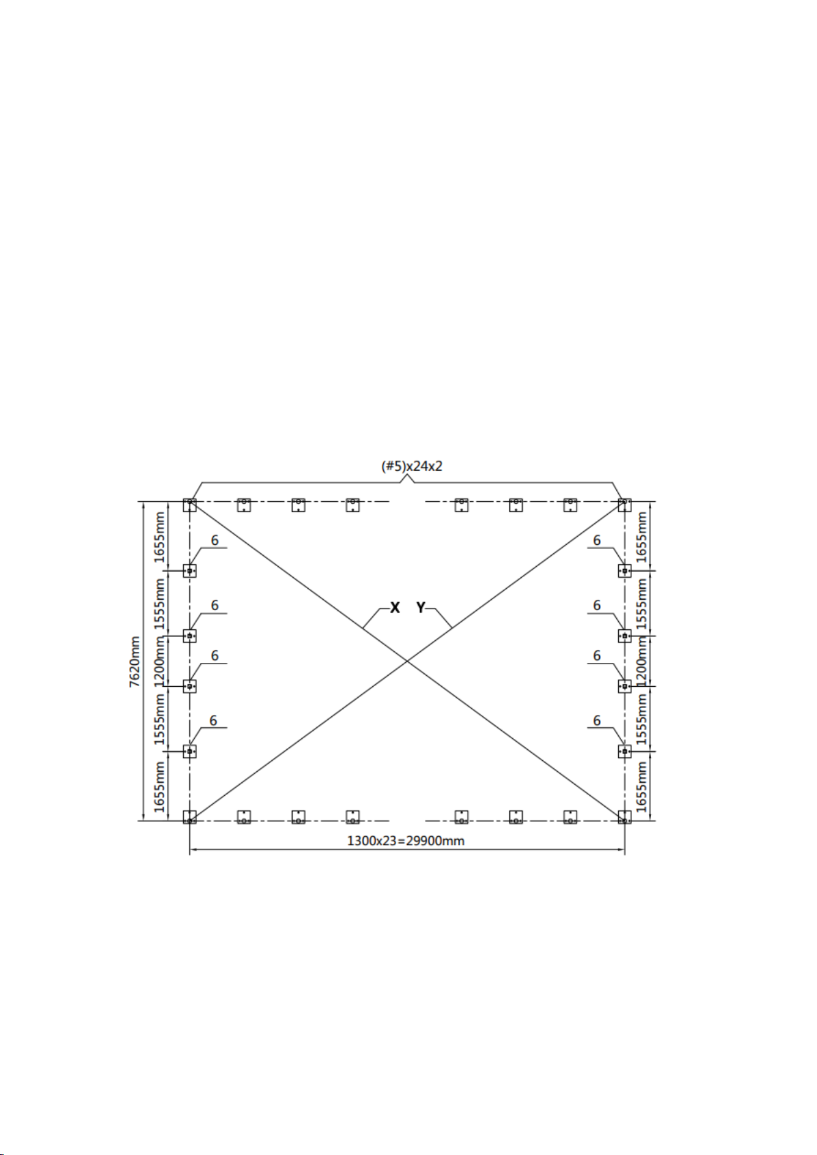
Overall assembled size : W7.62 x L29.9 x H3 (m) / W25 x L98 x H10 (ft)
Shoulder height : H1.2 (m) / 4ft
Door : W1.2 x H2 (m) / 4 x 6.6 (ft)
Prior to assembly
Please read the instructions carefully before installation. It is important to follow your
local safety regulations and industry standards during installation. Regulations may
include but are not limited to :
Safety helmets, protective eyewear, and clothing
Safety harnesses for all elevated workers
Proper ladder, cage, and safety operation
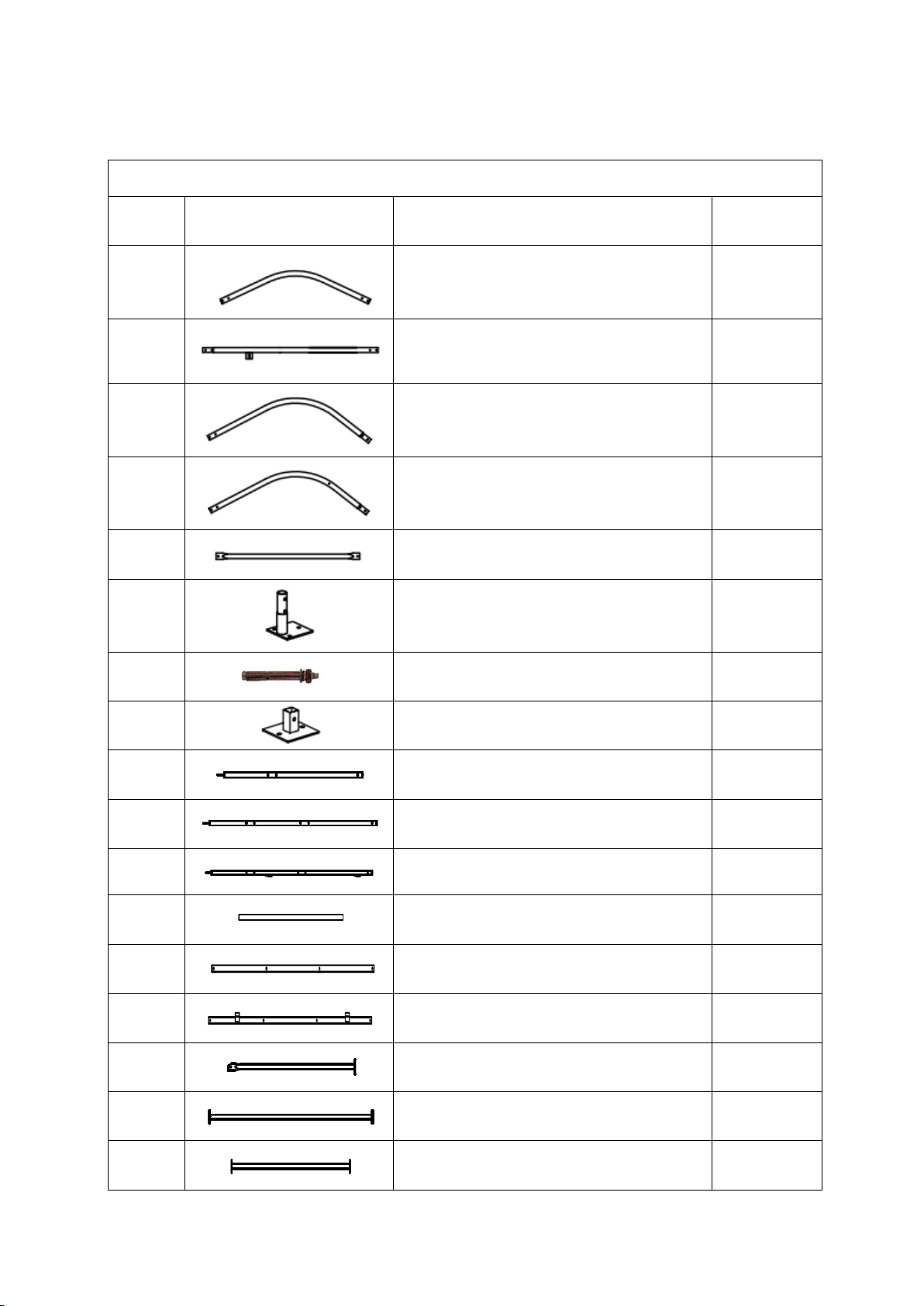
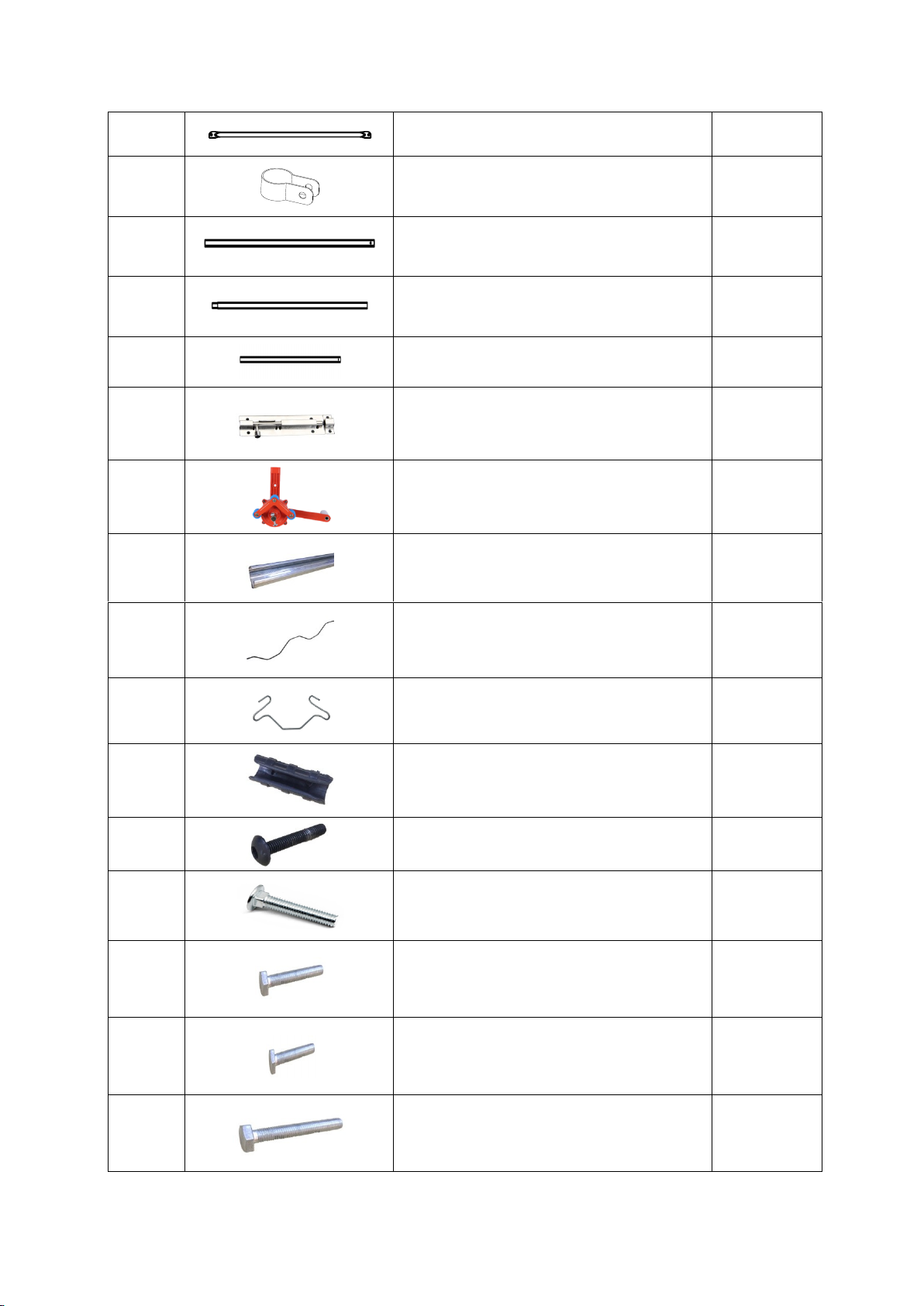
Check all components and parts before installation. All parts are marked with a part
number, please refer to the parts list to make sure you have all parts.
Choose a day with low or no wind to install, assembly is hard in heavy wind. Do not
make any alterations to the structure. Do not hang any weights on the frame during
installation, including parts. We are not responsible for any damages or injuries caused by
inappropriate installation, unauthorized modifications or extreme weather.
This building is not intended for human occupancy.
It is recommended to tape or add foam/rubber on the frame where joints connect and
where it touches the cover. This will help extend the life span of the cover.
Read the following item list carefully and count the number of items to ensure that all
parts are included prior to setup.

Page 2of 12
TMG-GH25100 Part List
Parts
code
Graphical
Description
Qty
1
Peak arch tube
24
2
Upper rafter tube
48
3
Shoulder tube
44
3A
Shoulder tube
(front and rear truss)
4
4
Roof purlin
(horizontal tube)
161
5
Base plate
48
5B
Expansion bolt M12x100mm
160
6
Door column base plate
8
7
Vertical tubes
4
8L
Door left vertical tubes
2
8R
Door right vertical tubes
2
9
Door horizontal tube
8
9L
Door frame column left tube
2
9R
Door frame column right tube
2
10
Door cross tubes
4
10A
Door cross tubes
4
10B
Door frame cross pull tube
2

Page 3of 12
11
Ceiling cross bar
24
12
Tube clamp
12
13
Film rolling machine guide tube
2
14
Roll film tube
30
14A
Roll film tube
2
15
Door buckle
2
16
Film rolling machine
2
17
Reed groove
98
17A
Clip spring
98
18
Eight clip spring
94
19
Pressure film carrier
48
20
Half round head bolt M6x50
16
21
Self locking bolt
M10x70mm and nuts
168
22
Hex bolt
M10x70mm and nuts
320
23
Hex bolt
M10x30mm and nuts
60
24
Hex bolt
M10x100mm and nuts
2

Page 4of 12
25
Self tapping screw #12x25
562
26
Self tapping screw #12x35
216
27
Square plug
8
28
Round plug(φ25)
6
29
Braided rope
1 bundle
(100m)
30
Top cover film
1
30A
Front and rear door film
2
31
Adhesive tape
4
32
Socket wrench
1
33
Hex wrench
1
34
Board 150x15x2000mm
(not included)
68
Installation steps
Step 1 : Review the whole structure and choose the proper installation site
Choose a solid flat level ground area to set up the building. Do not install the
building on soft ground, wetland, uneven surfaces, sloped surfaces.
We strongly recommend that you build the structure on a solid foundation such as
cement and use anchor bolts on all base plates.

Page 5of 12
Be aware of the surrounding area. Do not set up the building near snowdrifts, open
flames or exposed electrical wires. Do not keep heat sources near the fabric cover.
Keep the building surroundings clear at all times
Mark the ground in the final building location with a line showing the positions of
base plates, front doors. All lines should be drawn from center to center of all base
plate tubes. Diagonal line X must be equal to Y.
Base plates : all base plates must be installed firmly with expansion bolts (#5B) on
this step (refer to figure 1).
Parts used in this step :
-
(48) Base plate (#5)
-
(8) Door column base plate (#6)
-
(160) Expansion bolts (#5B)
Figure 1
Step 2 : Assemble all trusses
The building includes 24 trusses : (2) front and rear truss, and (22) middle trusses.
Parts used to install the front and rear truss in this step (refer to figure 2) :

Page 6of 12
-
(1x2) Peak arch tube (#1)
-
(2x2) Upper rafter tube (#2)
-
(2x2) Shoulder tube (#3A)
-
(1x2) Ceiling cross bar (#11)
-
(8x2) Hex bolt (#22)
-
(2x2) Hex bolt (#23)
Figure 2
Parts used to install (22) middle trusses in this step (refer to figure 3) :
-
(1x22) Peak arch tube (#1)
-
(2x22) Upper rafter tube (#2)
-
(2x22) Shoulder tube (#3)
-
(1x22) Ceiling cross bar (#11)
-
(8x22) Hex bolt (#22)
-
(2x22) Hex bolt (#23)
Figure3

Page 7of 12
Lay down all (24) trusses on the ground as figure 4 when the assembly is all
completed and before moving to next step.
Figure 4
Step 3 : Put up all trusses (refer to figure 5)
Put up the front truss, use hex bolt (#22) to secure the truss to the base plates.
Parts used in this step :
-
(4) Hex bolt (#22)
Figure 5

Page 8of 12
Repeat above step to put up all other trusses (from 2th to 24th truss), and
connect all purlin. Now the whole structure is completely up. (refer to figure
6)
Parts used in this step :
-
(7x23) Roof purlin (#4)
-
(7x24) Self locking bolt (#21)
-
(4x23) Hex bolt (#22)
Figure 6
Step 4 : Installation of front and rear trusses (refer to figure 7)
-
(2x2) Vertical tubes (#7)
-
(1x2) Door left vertical tubes (#8L)
-
(1x2) Door right vertical tubes (#8R)
-
(4x2) Door horizontal tube (#9)
-
(1x2) Door frame column left tube (#9L)
-
(1x2) Door frame column right tube (#9R)
-
(2x2) Door cross tubes (#10)
-
(2x2) Door cross tubes (#10A)
-
(1x2) Door frame cross pull tube (#10B)
-
(6x2) Tube clamp (#12)
-
(8x2) Half round head bolt (#20)
-
(16x2) Hex bolt (#22)
-
(6x2) Hex bolt (#23)
-
(4x2) Square plug (#27)

Page 9of 12
Figure 7
The whole structure inspection: check all components and trusses to make
sure the whole structure is squared to the base line drawn at the step 1. All
trusses must be set up righted at 90 degree. All purlin must be straight in line.
If any purlin are not in line with they will need to be corrected before moving
to the next step.
Now it is the time to secure all bolts and nuts firmed on the structure. But do
not over-tight the bolts, otherwise the tubes might be damaged.
Step 5 : Installing boards (#34) and reed groove (#17) (refer to figure 8)
Fix the board (#34) with self tapping screw (#26).
Fix the reed groove (#17) with the self tapping screw (#25).
Parts used in this step :
-
(98) Reed groove (#17)
-
(490) Self tapping screw (#25)
-
(216) Self tapping screw (#26)
-
(68) Boards (#34)

Page 10 of 12
Figure 8
Step 6 : Install front and rear cover panel (refer to figure 9)
Lift the film (#30A) and fix the film with a clip spring (#17A) from top to
bottom.
Install door buckle (#15) with self tapping screw (#25).
Cut the door film as shown.
Parts used in this step :
-
(19x2) Clip groove (#17A)
-
(1x2) Door buckle (#15)
-
(6x2) Self tapping screw (#25)
-
(1x2) Front and rear door film (#30A)

Page 11 of 12
Figure 9
Step 7 : Install the film and roll film system (refer to figure 10)
NOTE : The cover must be installed on a windless day. DO NOT attempt to install the
cover during windy conditions.
when you are ready to install the roof cover, unpack the cover and position it
parallel to the building frame on one side. The truss connection is wrapped
with adhesive tape (#31) to reduce the friction between the frame and the film.
the cover must be pulled over the top of the truss frame without being snagged
or stressed on any frame members. tighten the film evenly to eliminate
wrinkles and make the film flat and smooth. Do not over-tighten during the
adjustment process, otherwise it will cause unnecessary damage. At this time,
you can install a clip spring (#17A) to fix the film.
Installation of roll film systems.
A round plug (#28) is put on both ends of the film rolling machine guide tube
(#13), and the guide tube is mounted on the frame with a hex bolt (#24), and it
is required to swing freely. After using a self tapping screw (#25) to connect
the roll film tube (#14,#14A), lay it flat on both sides of the frame. The film
(#30) is wound on a roll film tube (#14,#14A), and clamped with a pressure
film carrier (#19). The film rolling machine (#16) drives the roll film tube
(#14,#14A) to be raised and lowered horizontally and flexibly without
jamming.
Install the eight clip spring (#18) and fasten the braided rope (#29)

Page 12 of 12
Parts used in this step :
-
(2) Film rolling machine guide tube (#13)
-
(30) Roll film tube (#14)
-
(2) Roll film tube (#14A)
-
(2) Film rolling machine (#16)
-
(60) Clip spring (#17A)
-
(94) Eight clip spring (#18)
-
(48) Pressure film carrier (#19)
-
(2) Hex bolt (#24)
-
(60) Self tapping screw (#25)
-
(6) Round plug (#28)
-
(1) Braided rope (#29)
-
(1) Top cover film (#30)
-
(4) Adhesive tape (#31)
Figure 10
After the Installation
Walk around and inspect the shelter periodically to make sure all components are
still firmly secured and the whole shelter is well supported. Check all bolts and nuts
as well as all connection points to make sure they are all in good position.
We strongly recommend you remove any snow from the roof immediately. Do not
leave any snow load on the roof overnight. Keep 3 feet of clearance on all sides at
all times. Do not allow snow to accumulate and pile up on the sides of the building.
Otherwise the pressure from the sides will push inwards and could lead to a
collapse.
This manual suits for next models
1
Table of contents
Other TMG Greenhouse Kit manuals
Popular Greenhouse Kit manuals by other brands

ACF Greenhouses
ACF Greenhouses UNIVENT instructions

BCG
BCG Traditional Series instructions

Richel
Richel J30309 Assembly instructions and user guide

USP
USP Duramax owner's manual

Halls Greenhouses
Halls Greenhouses Magnum 108 Assembly instructions

Mercia Garden Products
Mercia Garden Products 04GREEN0606SDPB-V1 General instructions