TMG TMG-GH1030R User manual

W W W . T M G I N D U S T R I A L . C O M P 0 / 12 T o l l F r e e : 1 - 8 7 7 - 7 6 1 - 2 8 1 9
Main Specifications:

W W W . T M G I N D U S T R I A L . C O M P 1 / 12 T o l l F r e e : 1 - 8 7 7 - 7 6 1 - 2 8 1 9
Main Specifications :
-Assembly size : W3 x L9 x H2 (m) / 10 x30 x 07 (ft)
-Front roll up door : 1.86 x 1(m) / 6.1 x 3.3 (ft)
Prior to assembly
Please read the instructions carefully before installation. It is important to follow your
local safety regulations and industry standards during installation. Regulations may
include but are not limited to :
- Safety helmets, protective eyewear, and clothing
- Safety harnesses for all elevated workers
- Proper ladder, cage, and safety operation
Check all components and parts before installation. All parts are marked with a part
number, please refer to the parts list to make sure you have all parts.
Choose a day with low or no wind to install, assembly is hard in heavy wind. Do not
make any alterations to the structure. Do not hang any weights on the frame during
installation, including parts. We are not responsible for any damages or injuries caused by
inappropriate installation, unauthorized modifications or extreme weather.
This building is not intended for human occupancy.
It is recommended to tape or add foam/rubber on the frame where joints connect and
where it touches the cover. This will help extend the life span of the cover.
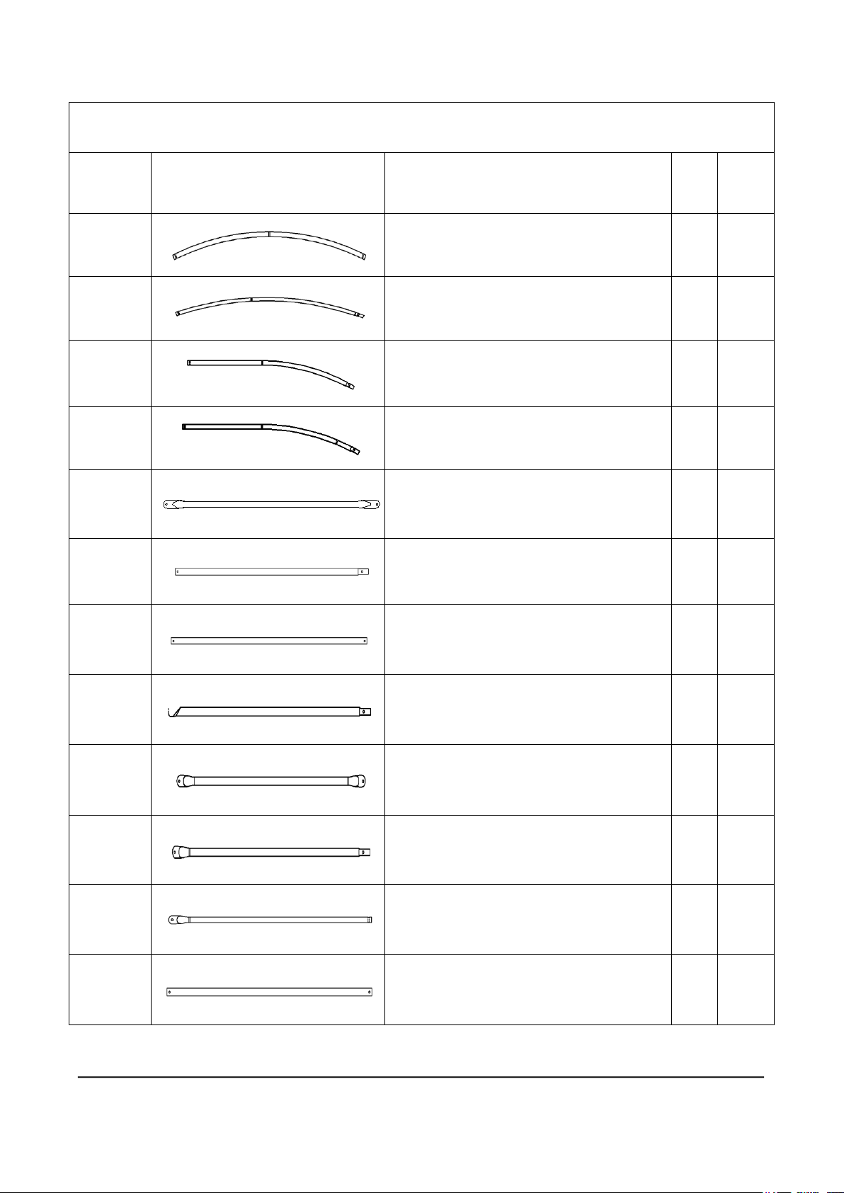
Read the following item list carefully and count the number of items to ensure that all
parts are included prior to setup.
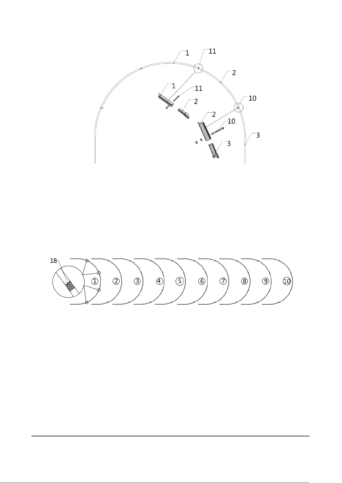
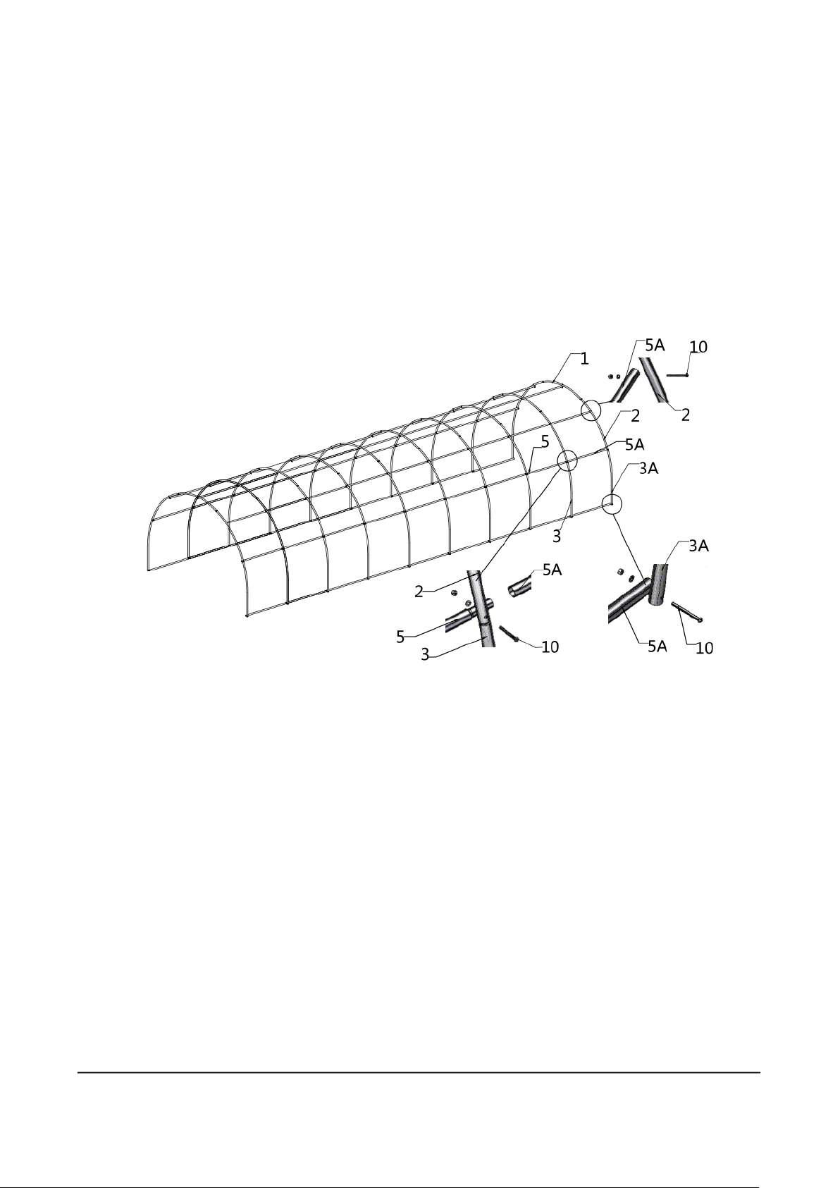
Installation steps
Step 1: Review the whole structure and choose the proper installation site
Choose a solid flat level ground area to set up the building. Do not install the building on
soft ground, wetland, uneven surfaces, sloped surfaces, or on top of structures that are not
rated to hold its weight.
We strongly recommend that you build the structure on a solid foundation such as cement
and use anchor bolts on all baseplates.
Be aware of the surrounding area. Do not set up the building near snowdrifts, open
flames or exposed electrical wires. Do not keep heat sources near the fabric cover.
Keep the building surroundings clear at all times.

W W W . T M G I N D U S T R I A L . C O M P 2 / 12 T o l l F r e e : 1 - 8 7 7 - 7 6 1 - 2 8 1 9
TMG-GH1030R Part List
Parts
code
Graphical
Description
Qty
BOX
1
Peak arch tube
10
1/1
2
Middle rafter tube
20
1/1
3
Lower rafter tube
(middle truss)
16
1/1
3A
Lower rafter tube
(front and rear truss)
4
1/1
4
Diagonal bracing bar
(1st and last span)
4
1/1
5
Roof purlin
(horizontal tube)
56
1/1
5A
Roof purlin
(horizontal tube)
7
1/1
6
Bottom tension bar
(front and rear cover)
4
1/1
6A
Door frame horizontal tube
(front truss)
2
1/1
6B
Frame horizontal tube
(rear truss)
1
1/1
6C
Frame horizontal tube
(rear truss)
1
1/1
7
Door frame lower horizontal tube
(front truss)
1
1/1

W W W . T M G I N D U S T R I A L . C O M P 3 / 12 T o l l F r e e : 1 - 8 7 7 - 7 6 1 - 2 8 1 9
7A
Bottom tension bar (rear cover)
1
1/1
7B
Ceiling cross bar (front truss)
1
1/1
8
Door frame lower tube
(front and rear truss)
3
1/1
8A
Door frame upper tube
(front truss)
2
1/1
8B
Upper tube (rear truss)
1
1/1
9
Tube clamp
6
1/1
10
Mushroom head hexagon socket
head bolt M6x65mm
71
1/1
11
Mushroom head hexagon socket
head bolt M6x40mm
31
1/1
12
Mushroom head hexagon socket
head bolt M6x30mm
6
1/1
13
Riding clip
22
1/1
14
Water plug
34
1/1
15
Cover
1
1/1
16
Expansion bolt M8x100mm
44
1/1
17
Hexagon wrench
2
1/1
18
Scratch resistant tape
2
1/1

W W W . T M G I N D U S T R I A L . C O M P 4 / 12 T o l l F r e e : 1 - 8 7 7 - 7 6 1 - 2 8 1 9
Step 2 : Assemble all trusses
The building includes 10 trusses : (1) Front truss, (1) rear truss, and (8) middle
trusses. The front truss fabric panels and the top fabric (#15) have been connected
as a whole.
Parts used to install the front truss and rear truss in this step (refer to figure 1) :
-(1x2) Peak arch tube (#1)
-(2x2) Middle rafter tube (#2)
-(2x2) Lower rafter tube ( #3A)
-(2x2) Mushroom head hexagon socket head bolt (#10)
-(2x2) Mushroom head hexagon socket head bolt (#11)
Figure 1
Parts used to install (8) middle trusses in this step (refer to figure 2).
-(1x8) Peak arch tube (#1)
-(2x8) Middle rafter tube (#2)
-(2x8) Lower rafter tube ( #3)
-(2x8) Mushroom head hexagon socket head bolt (#10)
-(2x8) Mushroom head hexagon socket head bolt (#11)

W W W . T M G I N D U S T R I A L . C O M P 5 / 12 T o l l F r e e : 1 - 8 7 7 - 7 6 1 - 2 8 1 9
Figure 2
Lay down all (10) trusses on the ground when the assembly is all completed
and before moving to next step, and then wrap (#18) around the sharp points
of the joint to avoid friction between the fabric and the interface, resulting in
fabric damage.(refer to figure 3)
Figure 3
Step 3 : Put up the front (1st) truss
First, erect the front truss. We suggest two or three people. One to two people hold
the truss and keep it upright and stable, while the other person installs the roof
purlin (#5). Use bolts (#10) to link the truss to the cross pull tube, and then tighten
all bolts. (refer to figure 4)
Parts used in this step :
-
(7) Roof purlin (#5)
-
(5) Mushroom head hexagon socket head bolt (#10)

W W W . T M G I N D U S T R I A L . C O M P 6 / 12 T o l l F r e e : 1 - 8 7 7 - 7 6 1 - 2 8 1 9
Figure 4
Step 4 : Put up the rest middle trusses
Repeat the previous step to erect the second span truss, and then connect the other
end Roof purlin (#5) with the truss with bolts (#10), and complete the installation of
the second truss to the sixth truss in turn. (refer to figure 5)
Parts used in this step :
-
(49) Roof purlin (#5)
-
(40) Mushroom head hexagon socket head bolt (#10)
Figure 5

W W W . T M G I N D U S T R I A L . C O M P 7 / 12 T o l l F r e e : 1 - 8 7 7 - 7 6 1 - 2 8 1 9
Step 5 : Put up the rest rear trusses
Finally, the rear truss (the 10th span truss) is erected, and then the Roof purlin
(#5A) is connected with the truss with bolts (#10). (refer to figure 6)
Parts used in this step :
-
(7) Roof purlin (#5A)
-
(5) Mushroom head hexagon socket head bolt (#10)
Figure 6
Step 6 : Install the diagonal bracing bars (#4)
Connect diagonal bracing bar (#4) on the first and last span between the Lower
rafter tube (#3A) and (#3) with tube clamp (#9), use bolt (#12) and ( #10) (figure 7)
Parts used in this step :
-
(4) Diagonal bracing bar (#4)
-
(4) Tube clamp (#9)
-
(4) Mushroom head hexagon socket head bolt (#12)

W W W . T M G I N D U S T R I A L . C O M P 8 / 12 T o l l F r e e : 1 - 8 7 7 - 7 6 1 - 2 8 1 9
Figure 7
Step 7 : Install the remaining parts on the front truss (figure 8)
Parts used in this step :
-
(2) Bottom tension bar (#6)
-
(2) Door frame horizontal tube (#6A)
-
(1) Door frame lower horizontal tube (#7)
-
(1) Ceiling cross bar (#7B)
-
(2) Door frame lower tube (#8)
-
(2) Door frame upper tube (#8A)
-
(2) Tube clamp (#9)
-
(6) Mushroom head hexagon socket head bolt (#11)
-
(2) Mushroom head hexagon socket head bolt (#12)
Figure 8

W W W . T M G I N D U S T R I A L . C O M P 9 / 12 T o l l F r e e : 1 - 8 7 7 - 7 6 1 - 2 8 1 9
Step 8 : Install the remaining parts on the rear truss (figure 9)
Parts used in this step :
-
(2) Bottom tension bar (#6)
-
(1) Frame horizontal tube (#6B)
-
(1) Frame horizontal tube (#6C)
-
(1) Bottom tension bar (#7A)
-
(1) Door frame lower tube (#8)
-
(1) Upper tube (#8B)
-
(1) Mushroom head hexagon socket head bolt (#10)
-
(5) Mushroom head hexagon socket head bolt (#11)
Figure 9
Step 9 : Install the waterproof plug and fix the truss
The ends of rafters (#3A) and (#3) at the lower part of the truss, as well as the
outer roof purlin (#5) and (#5A) at the front and rear truss, shall be provided with
waterproof plugs. (refer to figure 10)
Parts used in this step :
-
(34) Water plug (#14)

W W W . T M G I N D U S T R I A L . C O M P 10 / 12 T o l l F r e e : 1 - 8 7 7 - 7 6 1 - 2 8 1 9
Figure 10
Step 10 : Installation of riding clamp and waterproof plug
Fix the roof purlin (#5) and (#5A) close to the ground on the concrete ground with
riding clip (#13) and expansion bolt (#16). The installation dimension shown in
the figure is for reference (refer to figure 11). If the truss is installed on the earth
ground, it needs to be fixed by inserting at least 11 inch steel bars (not equipped
with this product cloth) into the riding clamp.
Parts used in this step :
-
(22) Riding clip (#13)
-
(44) Expansion bolt (#16)
Figure 11

W W W . T M G I N D U S T R I A L . C O M P 11 / 12 T o l l F r e e : 1 - 8 7 7 - 7 6 1 - 2 8 1 9
Step 11 : Installing fabric panel
Lift cover or panel (#15) to fully cover the truss, noting that the side with the door
needs to be placed on the front door arch. Then adjust the four sides evenly (refer to
figure 12)
Figure 12
Step 12 :Knitted fabric
Tie the left and right sides of the fabric and the rear truss to eliminate wrinkles. The
fabric is tensioned and tied to the roof purlin (#5) and (#5A) at the lower part of the
truss, and the bottom tension bar (#6) and (#7A) at the lower part of the rear truss
with the Velcro on the fabric. (refer to figure 13)
Figure 13

W W W . T M G I N D U S T R I A L . C O M P 12 / 12 T o l l F r e e : 1 - 8 7 7 - 7 6 1 - 2 8 1 9
Fasten the fabric front door. Use the Velcro on the fabric to tie the fabric tightly to
the bottom tension bar (#6) at the lower part of the front truss door frame lower tube
(#8) and door frame upper tube (#8A). (refer to figure 14)
Figure 14
After the Installation
Inspect the building periodically to make sure the parts are firmly fixed and the whole
building is well supported. Check all bolts and hardware connectors to make sure they are
in place and tightened. Check the base plates, adjust the ropes if necessary and clean the
cover regularly.
Snow accumulating on the fabric cover must be removed as soon as possible. If the snow
had become the solid ice on the cover, it would increase the burden of the roof and
collapse the building eventually or reduce the life span.
Keep the building on a dry ground condition most of the time. Do not keep the fabric dirt
skirt under water all the time, otherwise the fabric will deteriorate easily.
We strongly recommend you remove any snow from the roof immediately. Do not leave
any snow load on the roof overnight. Keep 3 feet clearance from both sides and two ends
of the ground all the time. Do not allow snow to accumulate and pile up on both sides of
the building. Otherwise the pressure from both sides will push toward the building and
make it collapse eventually.
Table of contents
Other TMG Greenhouse Kit manuals
Popular Greenhouse Kit manuals by other brands

Elite Greenhouses
Elite Greenhouses 6'3" WIDE HIGH EAVE Instructions & Illustrations

Juliana
Juliana Jubii 60 LE Assembly instructions

Vitavia
Vitavia VM0005-V Assembly instructions

GrowSpan
GrowSpan Gothic Cold Frame Series manual

Backyard Expressions
Backyard Expressions 911218 manual

oGrow
oGrow OGAL-CF23 instruction manual