manuals.online logo
Brands
  1. Home
  2. •
  3. Brands
  4. •
  5. Toastmaster
  6. •
  7. Food Warmer
  8. •
  9. Toastmaster HFS09 Operation manual

Toastmaster HFS09 Operation manual

1
ENGLISH
page 1
FRANÇAIS
page 5
ESPAÑOL
página 9
Middleby Cooking Systems Group  1400 Toastmaster Drive  Elgin, L 60120  (847)741-3300  FAX (847)741-4406
© 2001 Toastmaster, A Middleby Company.
is a registered trademark of Toastmaster, A Middleby Company. All rights reserved.
HFS09/HFS72
Domestic & Std. Export
ENGLISH/French/Spanish
P/N 39848
Rev. C  V1  5/01
WARNING: IN CASE OF FIRE
Disconnect the hot food server from its power source
IMMEDIATELY. This allows the unit to cool, making
it easier to put out the fire.
WARNING
OR YOUR SA ETY DO NOT STORE OR USE
GASOLINE OR OTHER LAMMABLE VAPORS OR
LIQUIDS IN THE VICINITY O THIS OR ANY OTHER
APPLIANCE
WARNING
IMPROPER INSTALLATION, ADJUSTMENT, AL-
TERATION, SERVICE OR MAINTENANCE CAN
CAUSE PROPERTY DAMAGE, INJURY OR DEATH.
READ THE INSTALLATION AND OPERATING IN-
STRUCTIONS THOROUGHLY BE ORE INSTALL-
ING OR SERVICING THIS EQUIPMENT.
WARNING
DISCONNECT THE UNIT ROM ITS ELECTRICAL
POWER SUPPLY BE ORE CLEANING OR SERVIC-
ING.
I. DESCRIPTION AND SPECIFICATIONS
A. Component Location
The major components of the hot food server are shown in Fig-
ure 1 below.
1. Temperature
adjustment knob
2. Power On/Off
(I/O) Switch
. Thermometer
5. Moisture
control slider
4. Removable
food pan
6. Heating element
(on floor of cabinet)
B. Component Function (see Figure 1)
1. Temperature adjustment knob - see Section , Operation.
2. Power On/Off ( /O) Switch - see Section , Operation.
3. Thermometer - see Section , Operation.
4. Removable food pan - holds the food product. The pan
can be removed for cleaning.
5. Moisture control slider - Opens and closes the moisture
vents in the front panel of the drawer.
6. Heating element - Provides heat to maintain the proper
temperature of the food product.
C. Operating and E ectrica Specifications
Pre-Heat Time: 20 minutes
Temperature range: 100-200°F (38-93°C)
Electrical Specifications/HFS09:
 120V, 50/60Hz, 1 Ph, 0.5kW, 4.2A
 Plug type: NEMA 5-15P
Electrical Specifications/HFS72:
 208V, 50/60Hz, 1 Ph, 0.4kW, 1.9A, OR
 240V, 50/60Hz, 1 Ph, 0.55kW, 2.3A
 Plug type: NEMA 6-15P
NOTE
An electrical wiring diagram is provided on the back cover of this
Manual.
Figure 1
Hot Food Server
Models HFS09, HFS72
OWNER'S OPERATING AND
INSTALLATION MANUAL
CAUTION
Using any parts other than genuine Toastmaster factory parts re-
lieves the manufacturer of all liability.
IMPORTANT
Contact your authorized service agent to perform maintenance and
repairs. A service agency directory is supplied with your hot food
server.
IMPORTANT
Toastmaster (manufacturer) reserves the right to change specifica-
tions and product design without notice. Such revisions do not entitle
the buyer to corresponding changes, improvements, additions or
replacements for previously purchased equipment.
RETAIN THIS MANUAL FOR FUTURE REFERENCE
This manual provides detailed information for the installation and
operation of your hot food server. t also contains information to assist
the operator in diagnosing problems in the event of a malfunction.
This manual is an important tool for the operator and should be kept
readily available.
ENGLISH
2
Control panel
mounting screws
II. INSTALLATION
IMPORTANT
IT IS THE CUSTOMERS RESPONSIBILITY TO REPORT ANY
CONCEALED OR NON-CONCEALED DAMAGE TO THE FREIGHT
COMPANY.
A. Insta ation Options and Kit Avai abi ity
Your hot food server is shipped from the factory with 4 NSF-listed
plastic legs, which may be used on single-unit or two-stack installa-
tions. The following kits are available from Toastmaster for additional
installation options:
 P/N ACCHFSC Casters kit (for 1-4 units)
 P/N ACCHFS6 6 legs kit (for 1-4 units)
 P/N ACCHFS9 9 legs kit (for 1-4 units)
All hot food server installations REQU RE the unit(s) to be mounted
on legs or casters prior to operation. The allowed installation configu-
rations are:
Supplied Cas ers 6 legs 9 legs
4 legs ki ki ki
Single uni YES YES YES YES
Two-s ack YES YES YES YES
Three-s ack NO YES YES YES
Four-s ack NO YES YES YES
CAUTION
STACKING MORE THAN FOUR SERVERS IS NOT PERMITTED.
B. Legs/Casters Assemb y
1. To install the supplied 4/102mm legs (1-2 units only), thread the
legs into the four holes on the bottom of the hot food server. An
illustration of the server with the supplied legs installed is shown
on the cover of this Manual. For a Two-Stack installation, attach
the legs to the bottom server only.
2. To install an optional Legs Kit or Casters Kit, refer to the instruc-
tions provided with the Kit.
C. Stacking the Hot Food Servers (2-4 units on y)
CAUTION
If you have ins alled he op ional Cas ers Ki , check ha he cas ers
are locked before s acking he ho food servers.
Perform the following steps, starting with the server that has legs/
casters installed:
1. Remove the two screws that hold the control panel in place. Be
sure to retain the screws. See Figure 2.
2. Gently pull the control panel out from the front of the unit and
allow it to hang by the wiring. DO NOT stretch or disconnect the
wiring! See Figure 2.
3. Remove the cap plug from the top panel of the unit. To remove
the plug, bend the tines on the underside of the plug in towards
the center using a pair of pliers. Then, lift the cap free and dis-
card it. See Figure 3.
4. Place a hot food server atop the unit. Check that all four sides of
the units are aligned.
5. Attach the two units together by inserting the supplied 3/8 bolt
from inside the control panel opening of the lower server, as shown
in Figure 4. The bolt passes through the hole in the top panel
and into the threaded leg hole in the floor of the upper unit. Tighten
the bolt to a LOOSE fit to allow the position of the units to be
adjusted.
6. At the rear of the upper server, remove the screws from BOTH
bottom rear corners, as shown in Figure 4. Then, loosen (do not
remove) the two screws on the lower server that hold the stack-
ing clips in place.
7. Reposition the stacking clips as shown in Figure 4, and replace
the two screws that you removed in Step 6. Tighten all four
screws.
8. Tighten the 3/8 bolt (that you installed in Step 5) to secure the
units together.
9. Replace the control panel, and fasten it in place with its screws.
10. Repeat Steps 1-9 until all units are stacked. Note that the cap
plug will remain in place on the top server in the stack.
D. E ectrica Connection
IMPORTANT
THE ELECTRICAL CONNECTION TO THE HOT FOOD SERVER
REQUIRES A CIRCUIT BREAKER/FUSED DISCONNECT. ELEC-
TRICAL SPECIFICATIONS ARE LISTED ON THE SERIAL PLATE
(SHOWN IN FIGURE 4), AND IN SECTION I OF THIS MANUAL.
CONSULT ALL APPLICABLE NATIONAL AND LOCAL CODES FOR
FURTHER ELECTRICAL CONNECTION REQUIREMENTS.
1. Before proceeding with the electrical connection, check the fol-
lowing for each hot food server:
a. Check that the electrical supply matches the hot food
servers requirements. Refer to the serial plate (Figure 4)
and to the electrical specifications shown in Section 1 of
this Manual.
b. Check that the appropriate receptacle is available for the
power cord plug.
WARNING
ENSURE THAT BOTH THE CIRCUIT BREAKER/FUSED DIS-
CONNECT AND THE POWER ON/OFF (I/O) SWITCH ARE
IN THE OFF (O) POSITION BEFORE PROCEEDING.
WARNING
ENSURE THAT ANY PACKING MATERIAL HAS BEEN RE-
MOVED FROM INSIDE THE CABINET AND FOOD TRAY.
3. nsert (each) power cord plug into its receptacle.
Figure 2
Figure 3
2. To remove,
bend tines in
towards
center of plug
1. Cap plug
shown
in place
. After stacking,
insert bolt
through cap hole
Figure 4 ( eft side shown - reposition brackets on BOTH sides)
Underside
of server
Control
panel
opened
Data plate
1. Remove
2. Loosen
. Reposition
4. Replace
5. Tighten
ENGLISH
3
III. OPERATION
A. Location and Function of Contro s
This section provides a basic description of the hot food server controls,
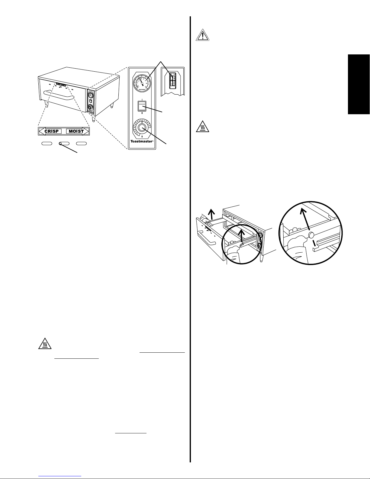
their location, and the functions they perform. The operator MUST be
familiar with the controls. See Figure 5.
1. Power On/Off (I/O) Swi ch
Switches the heating element ON ( ) and OFF (O).
2. Tempera ure adjus men knob
Adjusts the temperature setting of the heating element. This
controls the temperature of the cabinet and pan.
 1 is the minimum setting (100°F/38°C after preheating).
 9 is the maximum setting (200°F/93°C after preheating).
3. Thermome er
Displays the temperature of the cabinet and pan. A green zone
of 150-175°F (66-79°C) shows the optimum temperature range
for most food products.
4. Mois ure con rol slider
Opens and closes the moisture vents in the front panel of the
drawer.
 Moving the slider to the CR SP (left) position opens the
vents, allowing moisture to escape and causing a crisper
food product.
 Moving the slider to the MO ST (right) position closes the
vents, trapping moisture inside the cabinet and food product.
B. Operation Procedure
1. Restore electrical power to the hot food server at the circuit
breaker/fused disconnect. Switch the Power On/Off ( /O) switch
to the ON ( ) position.
2. Turn the temperature adjustment knob (if necessary) to the
desired setting for the food product.
3. Allow the hot food server to preheat for 20 minutes.
CAUTION - HOT SURFACE
USE CAUTION WHEN LOADING FOOD INTO, AND
REMOVING FOOD FROM, THE PAN. THE SURFACES OF
THE PAN ARE HOT.
4. Open the drawer. Load the food product into the pan, and close
the drawer. Check that the drawer is fully closed to prevent heat
loss into the environment.
5. Move the moisture control slider (if necessary) to open or close
the moisture vents, as required by the food product.
6. The food product will be kept at the temperature shown on the
thermometer. When unloading the product, use caution to avoid
touching the hot surfaces of the pan.
IMPORTANT
I may be necessary o clean he pan af er removing some food
produc s. Refer o Sec ion IV, Daily Cleaning, in his Manual.
C. Shutdown Procedure
1. Switch the Power On/Off ( /O) switch to the OFF (O) position.
Disconnect electrical power to the hot food server at the circuit
breaker/fused disconnect.
2.
Temperature
adjustment
knob
1. Power
On/Off (I/O)
Switch
. Thermometer
4. Moisture
control slider
Figure 5
IV. DAILY CLEANING
WARNING
WHEN CLEANING THE HOT FOOD SERVER, NEVER
APPLY ENOUGH LIQUID TO STAND IN PLACE ON THE
UNIT. DO NOT SPRAY, RINSE, OR SUBMERGE THE HOT
FOOD SERVER. EXCESSIVE MOISTURE IN THE UNIT
WILL CAUSE A SEVERE ELECTRICAL HAZARD AND MAY
OTHERWISE DAMAGE THE HOT FOOD SERVER.
CAUTION
DO NOT clean your ho food server using abrasive cleaners or pads.
Bo h will scra ch and dull he finish.
1. Switch the Power On/Off ( /O) Switch to the OFF (O) position.
2. Disconnect electrical power to the hot food server at the circuit
breaker/fused disconnect.
3. Allow the hot food server to cool.
CAUTION - HOT SURFACE
DO NOT TOUCH HOT SURFACES ON THE HOT FOOD
SERVER, OR ATTEMPT TO REMOVE THE PAN, UNTIL THE
UNIT HAS COOLED THOROUGHLY.
5. Cleaning he Cabine In erior and Drawer
a. Remove the drawer from the cabinet as follows:
 Open the drawer AND REMOVE THE PAN.
 Lift both side rails of the drawer until the rollers are
free, as shown in Figure 6.
 Pull the drawer forward, up, and out of the hot food
server.
b. Use a stiff nylon brush to loosen food particles and crumbs
from the following areas:
 drawer rails
 drawer rollers
 cabinet interior
c. Wipe or vacuum the food residue from the interior of the
cabinet.
d. Rinse the drawer rails, drawer rollers, and cabinet interior
with a sponge or cloth soaked in warm detergent water.
e. Wipe the components with a clean, damp cloth, and allow
them to air dry.
5. Cleaning he Pan
a. Empty the contents of the pan.
b. Wash the pan in hot soapy water, and rinse it. Allow the
pan to air dry.
NOTE: If desired, he pan can be pre-rinsed, run hrough a
dishwa er, and hen air-dried.
6. Cleaning he Ex erior of he Ho Food Server
a. Wipe the exterior of the cabinet with a sponge or cloth
soaked in warm detergent water.
b. Wipe with a clean, damp cloth to remove the excess
detergent, and then wipe again to dry the hot food server.
NOTE: If desired, he ex erior surfaces of he cabine can be
cleaned using a s ainless s eel cleaner/polish. Be sure o wipe
he polish in he direc ion of he grain o avoid scra ching he
finish.
7. Replace all components into the hot food server.
Figure 6
ENGLISH
page 1
FRANÇAIS
page 5
ESPAÑOL
página 9
A Middleby Company
Toastmaster  1400 Toastmaster Drive  Elgin, IL 60120  USA  (847)741-3300  AX (847)741-4406
Middleby Corp 24-Hour Service Hotline 1-800-238-8444
www.middleb .com
Wiring Diagram
BLACK
L1
Electrical Schematic
WH TE
NEUTRAL
GND
LAMP
POWER ON/OFF
( /O) SW TCH
THERMOSTAT
THERMOSTAT BULB
HEAT NG
ELEMENT
HFS09:
120V/500W
HFS72:
230V/500W
BLACK
L1
WH TE
NEUTRAL
GND
LAMP
THERMOSTAT
HEAT NG
ELEMENT
HFS09: 120V/500W
HFS72: 230V/500W
POWER ON/OFF
( /O) SW TCH

This manual suits for next models

1

Other Toastmaster Food Warmer manuals

Toastmaster 1503t User manual

Toastmaster

Toastmaster 1503t User manual

Toastmaster 9451-HP34CDNF User manual

Toastmaster

Toastmaster 9451-HP34CDNF User manual

Toastmaster 7500-H-UA13T User manual

Toastmaster

Toastmaster 7500-H-UA13T User manual

Toastmaster E6UAC-20 User manual

Toastmaster

Toastmaster E6UAC-20 User manual

Toastmaster 7500-H-UA13TP User manual

Toastmaster

Toastmaster 7500-H-UA13TP User manual

Toastmaster E17UAC-20 User manual

Toastmaster

Toastmaster E17UAC-20 User manual

Toastmaster HPU6 User manual

Toastmaster

Toastmaster HPU6 User manual

Toastmaster 3A81D Operation manual

Toastmaster

Toastmaster 3A81D Operation manual

Toastmaster 3B84DT09 User manual

Toastmaster

Toastmaster 3B84DT09 User manual

Toastmaster 3B20A User manual

Toastmaster

Toastmaster 3B20A User manual

Toastmaster 3B82D Owner's manual

Toastmaster

Toastmaster 3B82D Owner's manual

Toastmaster E9451-HP34CDNF User manual

Toastmaster

Toastmaster E9451-HP34CDNF User manual

Toastmaster 9451-HP34CDN User manual

Toastmaster

Toastmaster 9451-HP34CDN User manual

Toastmaster 3B84D User manual

Toastmaster

Toastmaster 3B84D User manual

Toastmaster 3B84A User manual

Toastmaster

Toastmaster 3B84A User manual

Toastmaster 7500-H-UA13T User manual

Toastmaster

Toastmaster 7500-H-UA13T User manual

Toastmaster HPU17 User manual

Toastmaster

Toastmaster HPU17 User manual

Toastmaster 9451-HP12CDNF User manual

Toastmaster

Toastmaster 9451-HP12CDNF User manual

Toastmaster 3A81D User manual

Toastmaster

Toastmaster 3A81D User manual

Toastmaster TECF1523 User manual

Toastmaster

Toastmaster TECF1523 User manual

Toastmaster TTS2 User manual

Toastmaster

Toastmaster TTS2 User manual

Toastmaster 3A81D User manual

Toastmaster

Toastmaster 3A81D User manual

Toastmaster E9451-HP34CDN User manual

Toastmaster

Toastmaster E9451-HP34CDN User manual

Toastmaster 3A80A User manual

Toastmaster

Toastmaster 3A80A User manual

Popular Food Warmer manuals by other brands

Star Manufacturing Stainless Steel and Lighted Models Specifications

Star Manufacturing

Star Manufacturing Stainless Steel and Lighted Models Specifications

Hamilton Beach proctor silex use & care

Hamilton Beach

Hamilton Beach proctor silex use & care

Bloomfield MOD-100 installation instructions

Bloomfield

Bloomfield MOD-100 installation instructions

Avantco W50 user manual

Avantco

Avantco W50 user manual

Medax 12801 instruction manual

Medax

Medax 12801 instruction manual

Hatco MACHO NACHO FDW-1-MN Series Specifications

Hatco

Hatco MACHO NACHO FDW-1-MN Series Specifications

Jura 571 Instructions for use

Jura

Jura 571 Instructions for use

Panasonic SR-DF101 Service manual

Panasonic

Panasonic SR-DF101 Service manual

Merco HFS-1B Operator's manual

Merco

Merco HFS-1B Operator's manual

Royal Catering RCHW 800 user manual

Royal Catering

Royal Catering RCHW 800 user manual

Momert 1706 operating manual

Momert

Momert 1706 operating manual

Cecilware FW24M Operator's manual

Cecilware

Cecilware FW24M Operator's manual

Server 81220 manual

Server

Server 81220 manual

Dacor 36 Planning guide

Dacor

Dacor 36 Planning guide

Panasonic SR-DE183 Service manual

Panasonic

Panasonic SR-DE183 Service manual

Werkmeister Kryotherm atur Instructions for use

Werkmeister

Werkmeister Kryotherm atur Instructions for use

Buffalo L310 instruction manual

Buffalo

Buffalo L310 instruction manual

Olympia Milan CN607 instruction manual

Olympia

Olympia Milan CN607 instruction manual

manuals.online logo
manuals.online logoBrands
  • About & Mission
  • Contact us
  • Privacy Policy
  • Terms and Conditions

Copyright 2025 Manuals.Online. All Rights Reserved.