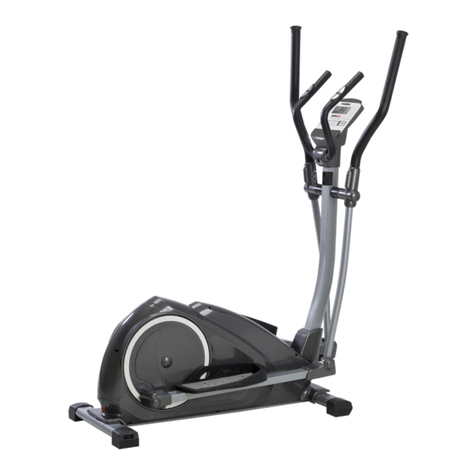
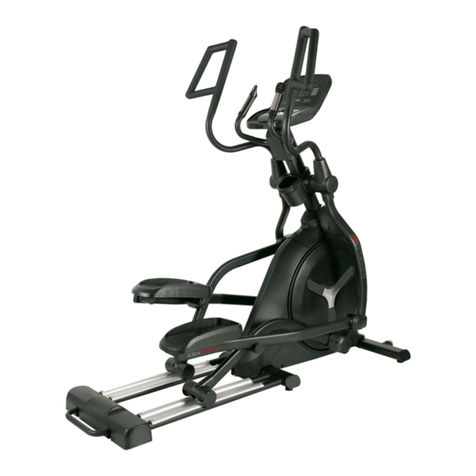
TOORX CHRONO LINE ERX500 User manual

Ed : 09/17 Rev : 00
INSTRUCTION
iConsole App Manual
www.toorx.it/iconsole

4
Assembly Pack Checklist
Hardware Step 1
(not shown at actual size)
Hardware Step 2
(not shown at actual size)
#114. Ø10 × 2T
Spring Washer (2 pcs) #112. Ø8 × 23 × 1.5T
Curved Washer (2 pcs) #113. Ø3/8" × 23 × 2.0T
Curved Washer (2 pcs)
#83. M5 × 10mm
Phillips Head Screw (4 pcs) #103. Ø5/16" × 23 × 1.5T
Flat Washer (4 pcs)
#76. 5/16" × 3/4"
Hex Head Bolt (6 pcs) #78. 3/8" × 3-3/4"
Hex Head Bolt (2 pcs)
#104. Ø8.5 × 26 × 2T
Flat Washer (4 pcs)
#76. 5/16" × 3/4"
Hex Head Bolt (2 pcs) #77. 5/16" × 15mm Button
Head Socket Bolt (2 pcs)
#124. Ø17
Wave Washer (2 pcs)

5
Hardware Step 3
(not shown at actual size)
Hardware Step 4
(not shown at actual size)
Assembly Tools
#112. Ø8 × 23 × 1.5T
Curved Washer (6 pcs) #76. 5/16" × 3/4"
Hex Head Bolt (6 pcs)
#86. 3.5 × 12mm
Sheet Metal Screw (6 pcs) #84. M5 × 15mm
Phillips Head Screw (2 pcs)
#121. Combination M5 Allen Wrench
& Phillips Head Screw Driver (1 pcs) #120. Phillips Head Screw Driver (1 pcs)
#118. 12/14m/m_Wrench (1 pcs) #119. 13/14m/m_Wrench (1 pcs)

6
ASSEMBLY
UNPACKING THE UNIT
1. Using a razor knife (Box Cutter) cut the outside, bottom, edge of box along the dotted
Line. Lift Box over the unit and unpack.
2. Carefully remove all parts from carton and inspect for any damage or missing parts. If
damaged parts are found, or parts are missing, contact your dealer immediately.
3. Locate the hardware package. The hardware is separated into steps. Remove the tools
first. Remove the hardware for each step as needed to avoid confusion.
ASSEMBLY INSTRUCTIONS
1 MAST ASSEMBLY
1. Locate the Console Mast (9) and Console Mast Cover (54) and slide the Cover onto the
Mast as far as it will go. Make sure the Console Mast Cover (54) is facing the correct way.
2. At the top opening of the Main Frame (1) of the elliptical is a Computer Cable (33).
Unravel and straighten out the Computer Cable (33) and feed it into the bottom of the
Console Mast tube (9) and out of the top opening.
3. Install the Console Mast (9) into the receiving bracket in the top of the Main Frame (1).
Put the 6pcs of 5/16" × 3/4"_ Hex Head Bolts (76) and 4pcs of Ø5/16" × Ø23 × 1.5T_Flat
Washers (103), 2pcs Ø8 × 23 × 1.5T_Curved Washers (112). Install, and hand tighten by
using the 12.14m/m Wrench (118).
NOTE: There is a electrical wire running through the Console Mast Tube (9). Be careful
not to damage or pinch this Computer Cable (33) during this procedure.
4. Connect the Front Stabilizer Bar (2) with the main frame at front joining plate by using
12/14 mm Wrench (118) to tighten 2pcs of 3/8" × 3-3/4"_Hex Head Bolt (78) , 2pcs of
Ø10 × 2T_Split Washers (114) and 2pcs of Ø3/8" × 23 × 2.0T_Curved Washer (113).
5. Place Console Assembly (32) on Console Mast , the Computer Cable (33) and
Handpulse W/Cable Assembly (37) and Handpulse W/Cable Assembly(Red)(37) plug
into the console (the same color to same color). Place console on the fixed tablets of
Console Mast ; then screw up with 4 pcs M5 × 10m/m_Phillips Head Screw (83) by
Phillips Head Screw Driver (120)(Note : Make sure the wires inserted into the riser . Do
not press the wire)

7

8
2 HANDLE BAR ASSEMBLING
1. Place 2pcs Ø17_Wave Washer (124) into the center axle of Console Mast. Then place
Lower Handle Bar (L) (10) into left center axle of Console Mast, screw up with 5/16" ×
3/4"_Hex Head Bolt (76) and Ø8.5 × Ø26 × 2.0T_Flat Washer (104) by
12/14m/m_Wrench (118). Same way to screw up Lower Handle Bar (R) (11) into right
center axle of Console Mast.
2. Insert the shaft on left connecting arm (7) to the bushing on left pedal arm (5) and secure
with 5/16" × 15m/m Button Head Socket Bolt (77) together with Ø8.5 × 26 × 2.0T Flat
Washer (104) by using Combination M5 Allen Wrench & Phillips Head Screw Driver (121).
Do it the same way for right connecting arm (8) and right pedal arm (6).
3. Release Swing for Axle which are on left and right connecting arms (7.8). Connect the left
and right connecting arm (7.8) with left and right lower handle bar (10.11) and secure with
Swing for Axles and the screw by using 12/14m/m_Wrench (118).

9
3 CONNECTING ARM ASSEMBLING
1. Install the Left and Right Swing Arms (14 & 15) into the Lower Left and Right
Lower Handle Bars (10 & 11) with 6pcs of 5/16" × 3/4"_Hex Head Bolts (76) and
6pcs of Ø8 × 23 × 1.5T_Curved Washer (112) by using the 12.14m/m_Wrench
(118).

10
4 PLASTICS PARTS ASSEMBLING
1. Install the 2pcs of Slide Wheel Covers (68) and the 2pcs of M5 × 15mm_Phillips Head
Screws (84) by using the Phillips Head Screw Driver (120).
2. Attach front (69) and rear (70) handle bar covers together on left swing arm shaft and use
3pcs of 3.5 × 12m/m_Sheet Metal Screws (86) to secure with Phillips Head Screw Driver
(120). Install them the way for the right side on handle bar covers (71) and (72).
3. Knocked 4pcs of Ø40 × Ø80_Oval End Cap (45) into Main Frame 4 corner by plastic
hammer.
Your unit is now fully assembled. Ensure all nuts and bolts are firmly tightened prior to use.

11
OPERATION OF YOUR CONSOLE
DISPLAY FUNCTIONS :
ITEM DESCRIPTION
TIME
.Workout time displayed during exercise.
.Range 0:00 ~ 99:59
SPEED
.Workout speed displayed during exercise.
.Range 0.0 ~ 99.9 KM(ML) / H
DISTANCE
.Workout distance displayed during exercise.
.Range 0.0 ~ 99.9 KM/ML
CALORIES
.Burned calories during workout display.
.Range 0 ~ 9999
PULSE
.Pulse bpm displayed during exercise.
.Pulse alarm when over preset target pulse.
RPM
.Rotation per minute
.Range 0 ~ 999
WATT
.Workout power consumption
.Range 0 ~ 999
. In Watt constant mode, computer will remain preset watt value (setting range
0~350)
MANUAL
.Manual mode workout.
BEGINNER
.4 PROGRAM selection.
ADVANCE
.4 PROGRAM selection.
SPORTY
.4 PROGRAM selection.
WATT
PROGRAM
.WATT constant training mode.
CARDIO
.Target HR training mode.

12
KEY FUNCTION:
OPERATION:
POWER ON
Plug in power supply, computer will power on and display all segments on LCD for 2 seconds.
After 4 minutes without pedaling or pulse input, console will enter into power saving mode.
Press any key may wake the console up.
WORKOUT SELECTION
Press UP and Down to select workout Manual Beginner Advance Sporty
Cardio Watt
Manual Mode
Press START in main menu may start workout in
manual mode.
1. Press UP or DOWN to select workout program,
choose Manual and press Mode to enter.
2. Press UP or DOWN to preset TIME, DISTANCE,
CALORIES, PULSE and press MODE to confirm.
3. Press START/STOP keys to start workout.
Press UP or DOWN to adjust load level.
4. Press START/STOP keys to pause workout.
Press RESET to reverse to main menu.
ITEM
DESCRIPTION
UP
. Increase resistance level
. Setting selection.
DOWN
. Decrease resistance level
. Setting selection.
MODE
. Confirm setting or selection.
RESET
. Hold on pressing for 2 seconds, computer will reboot and start from user setting.
. Reverse to main menu during presetting workout value or stop mode.
START/ STOP
. Start or Stop workout.
RECOVERY
. Test heart rate recovery status.
BODY FAT
. Test body fat% and BMI.

16
Beginner Mode
1. Press UP or DOWN to select workout program,
choose Beginner mode and press Mode to enter.
2. Press UP or DOWN to preset TIME.
3. Press START/STOP key to start workout.
Press UP or DOWN to adjust load level.
4. Press START/STOP key to pause workout.
Press RESET to reverse to main menu.
Advance Mode
1. Press UP or DOWN to select workout program,
choose Advance mode and press Mode to enter.
2. Press UP or DOWN to preset TIME.
3. Press START/STOP key to start workout.
Press UP or DOWN to adjust load level.
4. Press START/STOP key to pause workout.
Press RESET to reverse to main menu.
Sporty Mode
1. Press UP or DOWN to select workout program,
choose Sporty mode and press Mode to enter.
2. Press UP or DOWN to preset TIME.
3. Press START/STOP key to start workout.
Press UP or DOWN to adjust load level.
4. Press START/STOP key to pause workout.
Press RESET to reverse to main menu.
Cardio Mode
1. Press UP or DOWN to select workout program, choose H.R.C. and press Mode to enter.
2. Press UP or Down to select 55%.75%.90% or TAG (TARGET H.R.) (default: 100).
3. Press UP or DOWN to preset workout TIME.
4. Press START/STOP key to start or stop workout. Press RESET to reverse to main menu.

17
Watt Mode
1. Press UP or DOWN to select workout program, choose WATT and press Mode to enter.
2. Press UP or DOWN to preset WATT target. (default: 120)
3. Press UP or DOWN to preset TIME.
4. Press START/STOP key to start workout. Press UP or DOWN to adjust Watt level.
5. Press START/STOP key to pause workout. Press RESET to reverse to main menu.
RECOVERY
1. After exercising for a period of time, keep holding on handgrips and press “RECOVERY”
button. All function display will stop except “TIME” starts counting down from 00:60 to 00:00.
2. Screen will display your heart rate recovery status with the F1, F2….to F6. F1 is the best, F6
F6 is the worst. User may keep exercising to improve the heart rate recovery status.
(Press the RECOVERY button again to return the main display.)
BODY FAT
1. In STOP mode, press the BODY FAT button to start body fat measurement.
2. Console will remind to input user GENDER, AGE, HEIGHT, WEIGHT, then begin to
measure.
3. During measuring, users have to hold both hands on the hand grips. And the LCD will
display “= ” “= = ” for 8 seconds until computer finish measuring.
4. LCD will display BODY FAT advice symbol, BODY FAT percentage (Drawing 22), BMI for
30 seconds.
5. Error message:
*The LCD displays “= = ” “ = =”–means not hand the grip or wear chest strap correctly.
*E-1–There is no heart rate signal input detected.
*E-4–Occurs when FAT% is below 5 or exceeds 50 and BMI result is below 5 or exceeds 50.

18
Reminder:
1. When user stop pedaling for 4 minutes, computer will enter into power save mode, all setting
and exercise data will stored until user start exercise again.
2. When console act abnormal, please plug out the adaptor and plug in again.
3. If actual Heart Rate is over 230 or under 30, console will display “P” in 4seconds and not
show Heart Rate symbol.
iConsole+ APP
Turn on Bluetooth on phone / tablet, search for console device and press connect.
Turn on iconsole+ app on phone / tablet, and press connect to start workout with phone / tablet.
(password: 0000)
NOTE:
1. Once console is connect to phone/tablet via Bluetooth, the console will power off.

19
EXPLODED VIEW DIAGRAM

20
PARTS LIST
NO.
DESCRIPTION
Q'ty
1 Main Frame 1
2 Front Stabilizer Bar 1
3 Crank Arm Assembly 2
5 Pedal Arm (L) 1
6 Pedal Arm (R) 1
7 Connecting Arm (L) 1
8 Connecting Arm (R) 1
9 Console Mast 1
10 Lower Handle Bar (L) 1
11 Lower Handle Bar (R) 1
12 Crank Axle 1
13 Idler Wheel Assembly 1
14 Swing Arm (L) 1
15 Swing Arm (R) 1
16
Axle Stopper
1
17 Swing for Axle 2
18
Axle for Slide Wheel
2
19 Ø11.9 × Ø8.5 × 15m/m_Rod End Sleeve 2
20 6004_Bearing 2
21 6203_Bearing 2
22 6003_Bearing 4
24
Aluminum Rail
2
25 360m/m_Steel Cable 1
26 Drive Belt 1
27 Flywheel 1
28 Magnet 1
29 Handgrip Foam 2
30 Drink Bottle Holder 1
32 Console Assembly 1
33 1350m/m_Computer Cable 1
34 350m/m_DC Power Cord 1
35 Gear Motor 1
36 500m/m_Sensor W/Cable 1
37 850m/m_Handpulse W/Cable Assembly 2
38 Power Adaptor 1
41 Ø20 × Ø40_Oval End Cap 2
42 Ø65_Transportation Wheel 2
43 Ø78_Slide Wheel , Urethane 2
44 Ø330_Drive Pulley 1
45 Ø40 × Ø80_Oval End Cap 6
46 Ø60 × 15mm_Adjustment Foot 2
47 Ø32(1.8T)_Button Head Plug 4
48 Ø35 × 10_Rubber Foot 4
49 Cover Swing Arm Axle 2
50 Ø15 × Ø8.6 × 38.5L_Sleeve 2
51 WFM-1719-12_Bushing 4
52 End Cap Stopper 4
53 J4FM-1719-09_Bushing 12

21
NO.
DESCRIPTION
Q'ty
54 Console Mast Cover 1
55 Side Case (L) 1
56 Side Case (R) 1
57 Side Case Plate(L) 1
58 Side Case Plate(R) 1
59 Pedal Arm Cover (L) 1
60 Pedal Arm Cover (R) 1
61 Handgrip End Cap 2
63 Crank Arm End Cap 2
66 Ø42 × Ø19 × 15L_Bushing 8
67 Ø42 × Ø19 × 21L_Bushing 4
68 Slide Wheel Cover 2
69 Front Handle Bar Cover (L) 1
70 Rear Handle Bar Cover (L) 1
71 Front Handle Bar Cover (R) 1
72 Rear Handle Bar Cover (R) 1
73 7 × 7 × 19mm_Woodruff Key 2
74 3/8" × 2"_Flat Head Socket Bolt 4
75 1/4" × UNC20 × 3/4"_Hex Head Bolt 4
76 5/16" × UNC18 × 3/4"_Hex Head Bolt 26
77 5/16" × 15m/m_Button Head Socket Bolt 2
78 3/8" × 3-3/4"_Hex Head Bolt 2
79 M8 × 35m/m_Socket Head Cap Bolt 2
81 5/16" × UNC18 × 1-3/4"_Button Head Socket Bolt 2
82 M5 × 10m/m_Phillips Head Screw 10
83 M5 × 10m/m_Phillips Head Screw 4
84 M5 × 15m/m_Phillips Head Screw 8
85 5 × 19m/m_Tapping Screw 9
86 3.5 × 12m/m_Sheet Metal Screw 18
87 3.5 × 16m/m_Sheet Metal Screw 9
88 3 × 20m/m_Tapping Screw 4
89 Ø17_C Ring 1
90 Ø20_C Ring 2
91 E7_E-Clip 2
92 1/4" × 8T_Nyloc Nut 4
93 5/16" × 7T_Nyloc Nut 2
94 M8 × 7T_Nyloc Nut 1
95 M8 × 9T_Nyloc Nut 1
97 M8 × 6.3T_Luck Nut 4
98 3/8" × UNF26 × 4T_Luck Nut 2
99 3/8" × UNF26 × 11T_Nut 2
100 3/8" × 7T_Luck Nut 8
101 Ø5 × Ø15 × 1.5T_Flat Washer 8
103 Ø5/16" × Ø23 × 1.5T_Flat Washer 5
104 Ø8.5 × Ø26 × 2.0T_Flat Washer 8
105 Ø3/8" × Ø19 × 1.5T_Flat Washer 4
106 Ø17 × Ø23.5 × 1.0T_Flat Washer 1
107 Ø20 × Ø30 × 2T_Flat Washer 1
109 M8 × P1.25 × 155L_J Bolt 1

22
NO.
DESCRIPTION
Q'ty
110 M8 × 20m/m_Carriage Bolt 1
111 M5 × 5m/m_Slotted Set Screw 2
112 Ø8 × 23 × 1.5T_Curved Washer 8
113 Ø3/8" × 23 × 2.0T_Curved Washer 2
114 Ø10 × 2T_Spring Washer 2
117 Ø5/16" × Ø23 × 3T_Flat Washer 8
118 12/14m/m_Wrench 1
119 13/14m/m_Wrench 1
120 Phillips Head Screw Driver 1
121 Combination M5 Allen Wrench & Phillips Head Screw Driver 1
122 Transformer Power Cord 1
123 Rubber Pad 1
124 Ø17 × 0.5T_Wave Washer 2
125 1/4" × 19_Flat Washer 1
130 Ø5/16" × Ø35 × 1.5T_Flat Washer 1

GARLANDO SPA
Via Regione Piemonte, 32 - Zona Industriale D1
15068 - Pozzolo Formigaro (AL) - Italy
www.toorx.it - info@toorx.it
Table of contents
Other TOORX Elliptical Trainer manuals
Popular Elliptical Trainer manuals by other brands

Freespirit
Freespirit C249 29282 0 owner's manual

Christopeit Sport
Christopeit Sport EL 7 Assembly and exercise instructions

Weslo
Weslo Momentum G 3.8 Elliptical manual

SportsArt Fitness
SportsArt Fitness 8100 incline calibration guide

Tunturi
Tunturi CE35 owner's manual

Spirit
Spirit Inspire ZE20 owner's manual