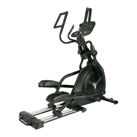
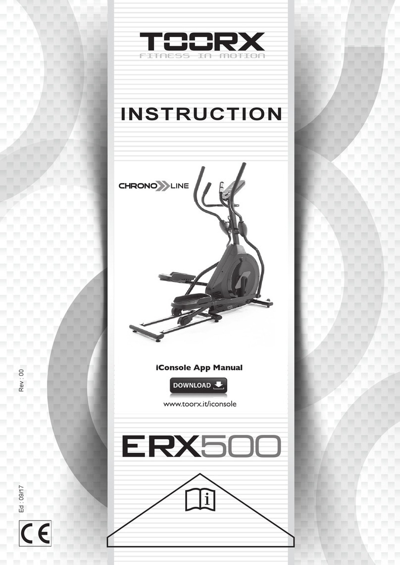
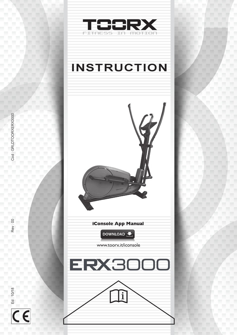
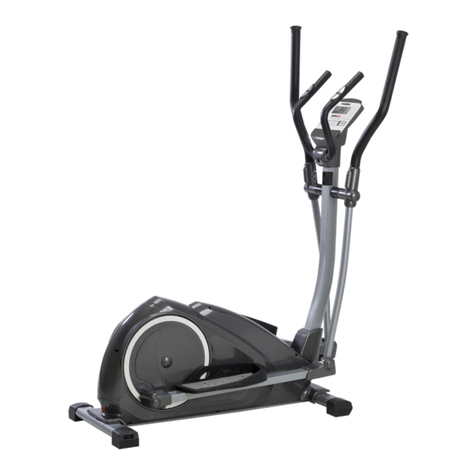
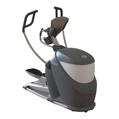
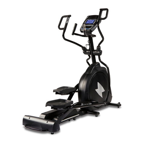
TOORX ERX3500 User manual

Ed : 10/18 Rev : 00 Cod : GRLDTOORXERX3500
INSTRUCTION
iConsole App Manual
www.toorx.it/iconsole

CHECK LIST (CONTENTS OF PACKAGE):
KH- 742S
Step 1
M8*1.25*20L 8PCS9
D15.4*D8.2*2T 8PCS
7
D22*D8.5*1.5T 2PCS
6
Step 2
M5*12L 8PCS ST4*15L 2PCS63
M8*1.25*20L 2PCS
40
Step 3
Step 4
Step 5
D25*D8.5*2T 2PCS
46
(MM)
78 D40 4pcs
D14 4PCS77
D25*D8.5*2T 2PCS
46
M8*1.25*50L 4pcs41 M8*1.25*20L 4P CS
9D15.4*D8.2*2T 8PCS
7
D16*D8.5 4pcs8
D16*D8.5 8pcs
8
M5*12L 2PCS
68
D25*D8.5*2T 2PCS46
M8*1.25* 20L 2PCS
9
M8*1.25* 20L 6PCS
9
D25*D8.5*2T 2PCS46
D15.4*D8.2*2T 4PCS
7
D22*D8.5*1.5T 4PCS
6
14 D26*D19.5 2PCS
D24*D10 2PCS
47
23 D50 2PCS
D46 2PCS
90
68
18 D29*D20*0.9T 2PCS
D24*D10 2PCS
47
D27*D8.2*2. 5T 2PCS
12 10 12 L&R
64
49
11 L&R
93L&R
81
19
44
21L&R
67
51
85
52L&R
x1
x1
x1 x1
x1
x1 x1
x1
x1 x1
x1
x2 x1
x1 x2
x1
x1
136
6

Exploded drawing:
46
47
1
2
19
5L
5L
5R
8
97
6
10
5R
32L
74
21L 11L
11R
90
27
63
76 38 66
3
17
4
31
39 79 24
33 95
61 57
33
69
35
62
49 37
36R36L
64 101
87
83
55
53
52R
52L
12L
12R
27
18
81
1565
89 47 70 94
50
56
60
16
75
25 29 30 106 86 22
45
34
43
27
43 58
42
72
73
88
92 99
102 104
97
98
80
77
78
42
9
41
105
84 82
6768
40
8
105
20
47
91
26
28
96
68
14
51
109
111
110
23
71
54
13
46
97
118
44
85
138
97 8
22
17
59
46
46
46
76
7 9
84
84
46
6
48 43 13
7

Part List:
Part NO. Description Material Specification QTY
1 Main frame 1
2 Front stabilizer 1
3 Sliding beam guiding plate Q235A R19.1*681*1.5T 2
4 Oval cap P.E. 40*60*11L 2
5L Tri angle cap(left) PE 95.7*57.2*51.3 2
5R Tri angle cap(right) PE 95.7*57.2*51.3 2
6 Curved washer Q235A D22xD8.5x1.5T 6
7 Spring washer 70# D15.4 XD8.2x2T 24
8 Flat washer Q235A D16*D8.5*1.2T 16
9 Allen bolt 35# M8x1.25x20L,8.8 22
10 Handlebar post 1
11L Supporting tube for left pedal 1
11R Supporting tube for right pedal 1
12L Supporting tube for left movable handlebar 1
12R Supporting tube for right movable handlebar 1
13 Spacer NL66 D21*D17.1*5T 2
14 Waved washer 65Mn D26*D19.5*0.3T 2
15 Mushroom cap PVC D1 1/4"*29L 2
16 Bearing GCr15 #99502 2
17 Hex nut Q235A M10*1.5*8T 6
18 Plastic washer NL66 D29*D20*0.9T 2
19 Sliding beam welding set 1
20 Bolt Q235A M6*1*15L 4
21L Left pedal PP 410.7*173.9*70 1
21R Right pedal PP 410.7*173.9*70 1
22 Adjustable round wheel Q235A D38*M10*1.5 6
23 Round cap PE D50x15L 2
24 Anti loose nut 35# M10*1.25*7T 2
25 Control board EMS2500 A01 1
26 Pedal pad TPU45+HIPS 354.9*134.5*9 2
27 Bearing #6004ZZ 10
28 Screw 10# ST4*1.41*14L 12
29 Upper computer cable 1000L 1
30 Lower computer cable 450L 1
31 Cap PE 40*80*33 2
32L Bracket for left pedal 1
32R Bracket for right pedal 1
8

Part NO. Description Material Specification QTY
33 Crank welding set 2
34 Nut Q235A M8*1.25*8T 1
35 Poly belt 450 PJ6 1
36L Left chain cover PS 698.8*597*71.9 1
36R Right chain cover PS 698.8*597*67.5 1
37 Magnetic system D265*86 1
38 Wheel PU D87.2*55L 2
39 Side cap PVC D36x14 2
40 Hex bolt 35# M8*1.25*20L 6
41 Allen bolt 35# M8*1.25*50L,8.8 4
42 Axle Q235A D17*48L 2
43 Bearing GCr15 #6003ZZ 12
44 Adaptor Output:26V,2.3A 1
45 Round magnet M02 1
46 Flat washer Q235A D25*D8.5*2T 14
47 Plastic washer NL66 D10*D24*0.4T 6
48 Connection cable 500L 1
49 Upper protective cover HIPS 137.1*121*73.4 1
50 Plastic cover PVC D3*30L 1
51 Wheel cover PP 93.2*64.7*62 2
52L Left movable handlebar 1
52R Right movable handlebar 1
53 Foam NBR D30x3Tx680L 2
54 Foam NBR D30x3Tx530L 2
55 Handlebar cap PVC 95.8*50.8 2
56 Spring 72A# D3*D19*67L 1
57 Hex bolt 35# M6x1.0x15L, 8.8 4
58 C ring 65Mn D22.5*D18.5*1.2T 4
59 Waved washer 65Mn D27*D20.3*0.5T 1
60 Waved washer 65Mn D21xD16.2x0.3T 1
61 Crank axle welding set 1
62 Belt wheel NL+ fiber D305x19.5 1
63 Screw 10# ST4*1.41*15L 2
64 Computer SE 1699 31 1
65 Handle pulse PE18 2
66 Axle of wheel 35# D17*61.2L 2
67 Protective cover ABS 100*81*40.8 1
9

68 Bolt Q235A M5*0.8*12L 10
Part NO. Description Material Specification QTY
69 Universal joint 2
70 Idle wheel fixing plate 1
71 Buffer SBR R23x35x43 2
72 Bushing D19.15x(D25.6x32)x L(17+3) 4
73 Side cap PVC D29.1*13L 4
74 Axle cover PE6070 D60*13.5L 4
75 C ring 65Mn S 16(1T) 1
76 C ring 65Mn S 17(1T) 8
77 Flat washer Q235A D14xD6.5x0.8T 4
78 Club knob ABS+CU D40*M6*12 4
79 Crank cover PS 339*102.6*29.9 2
80 Round side cap PE D45*15 2
81 Handle bar welding set 1
82 Computer fixing plate ABS 120*40*70 1
83 Screw 35# M8*1.25*45L 1
84 Nut Q235A M8*1.25*8T 5
85 Computer fixing plate Q235A 220*120*3T 1
86 Sensor cable 250L 1
87 Computer fixing bracket ABS 120*110*2.5T 1
88 Nut Q235A M6x1.0x6T 4
89 Hex nut Q235A M8*1.25*6T 2
90 Axle cover PVC D46*14.8 2
91 Screw Q235A ST4x25L 2
92 Pin ABS D6*26.5*7.7 1
93L Rear axle cover (left) PS 155*119.7*52.5 2
93R Rear axle cover (right) PS 155*119.7*55.5 2
94 Allen bolt 35# M8x1.25x30L ,8.8 1
95 Screw 10# ST4*1.41*15L 4
96 Flat washer Q235A D15*D5.2*1.0T 4
97 Handle pulse cable 700L 2
98 Oval side cap PE 30*70*10.5 6
99 Screw 10# ST4.2x1.4x20L 10
100 Allen bolt 35# M8*1.25*50L,8.8 1
101 Bolt 10# M5*0.8*15L,8.8 4
102 Wheel PP D65*24 2
103 Screw 35# M8*1.25*75L,8.8 2
10

104 Allen bolt Q235A M8*1.25*40L,8.8 2
105 Screw 10# ST4.2x1.4x15L 4
Part NO. Description Material Specification QTY
106 Electric cable 700L 1
107 Waved washer 65Mn D22xD17x0.3T 10
109 Screw 35# M6*1.0*15L,8.8 4
110 Flat washer Q235A D13*D6.5*1.0T 4
111 Spring washer 70# D10.5*D6.1*1.3T 4
112 Nut Fe D15*13L 1
113 Flat washer Q235A D24*D16*1.5T 1
114 Flat washer Q235A D50*D10*3T 1
115 Flat washer Q235A D28*D8.5*3T 1
116 Screw 10# ST4*1.41*12L 8
117 Bolt Q235A M5*0.8*10L 1
118 Buffer NBR 20*90*1.7T 2
136 Buffer PVC D27*D8.2*2.5T 2
137 Flat washer Q235A D26*D21*1.5T 1
138 Buffer EVA 219*15*2T 2
139 Spring washer NL66 D27*D18*1.0T 2
\ Allen spanner 35# M6, 8.8 1
\ Spanner Q235A 139*5T 1
11

STEP 1
Step 1
D15.4
M8*20 D16
98
x4
7
D25
D15.4
M8*20
97
D22
6
946
D15.4
7
M8*20
8
9
7
1
19
2
9
6
2 51
46
x2
1) Assemble the sliding beam welding set (19) to the main frame (1) by using the
curved washer (6), the spring washer (7), the Allen bolt (9) and the flat washer
(46).
2) Assemble the front stabilizer (2) to the main frame (1) by using the spring washer
(7), the flat washer (8) and the Allen bolt (9).
3) Mount the wheel cover (51) to the wheel. And you can adjust the proper height by
turning the wheel of foot cap.
12

STEP 2
Step 2
M8*20
ST4*15
M5*12
x2
x2
x4
x8
D14
D25 D27
2-1
2-2
2-3
90
46 40
63
77
78
11L
21L
11R
93L 93R
68
21L
11R
33
21R
78
63
40 46
77
68
1) Assemble the su orting tube (11L & 11R) to the crank welding set (33) by using the
buffer (136), the flat washer (46), the hex bolt (40) .Then assemble the axle cover (90) on
the two outside as the fig. 2-1.
2) Assemble the edal (21L & 21R) to the su orting tube (11L & 11R) by using the flat
washer (77) and the club knob (78) as the fig. 2-2.
3) Assemble the rear axle cover (93L & 93R) to the su orting tube (11L & 11R) by using
the screw (63), and the bolt (68) as the fig. 2-3.
13

STEP 3
Step 3
68 M5*12
D15.4
M8*20 D16
98
x4
7
41
D15.4 D16
8
x4
7
M8*50
x2
3-1
a
b
d
c
3 5
3-2
3-3
3-4
10
49
9
7
8
81
81
67 68
81
67
41
8
7
87 29
30
9
1) Suggest assembling this step by two persons.
2) First, lift up the upper protective cover (49) as fig. 3 1. Then connect computer
cable (29 & 30) as fig.3 2.
3) Insert the handlebar post (10) on the main frame and tighten it by using the flat
washer (8), the spring washer (7) and the Allen bolt (41). Place down the upper
protective cover (49) and make it tight on the main frame as fig.3 3.
4) Assemble the handlebar welding set (81) to the handlebar post (10) by using the
flat washer (8), the spring washer (7), and the Allen bolt (9) as fig.3 4.
5) Assemble the protective cover (67) by using the bolt (68) as fig.3 5.
14

STEP 4
Step 4
M8*20 x2
D25 D29*D20
D24 x2
4-1
4-2
946
18
10
946
18
10
23
52R
52L
52R
52L
10
23
47
47
946 18
47
4) Assemble the left and right movable handlebar (52L&52R) on the handlebar post
tube (10) by using the Allen bolt (9), the flat washer (46), the plastic washer (47)
and the plastic washer (18). Then assemble the round side cap (23) on the two
outside.
15

STEP 5
Step 5
x2
x4
D25 D24
D15.4
M8*20 D22
D26*D19.5
M8*20
5-1
5-2
5-3
5-4
6
9
7
6
9
7
14
47
9
46
14
47
9
46
32L
12L
12L
52L
52R
12R
12R
32R
12R
9
46 47 14
67
9
1) Assemble the left and right movable supporting tube (12L & 12R) to the bracket
for pedal (32L & 32R) by using the Allen bolt (9), the flat washer (46), the plastic
washer (47) and the waved washer (14) as fig. 5 1 & fig. 5 3.
2) Assemble the left and right movable handlebar (52L&52R) to the movable
supporting tube (12L & 12R) by using the curved washer (6), the spring washer
(7), and the Allen bolt (9) as fig. 5 2 & fig. 5 4.
16

STEP 6
Step 6
M5*15L
44
64
29
97
64
101
101
85
x4
1) Connect the upper computer cable (29) and the handle pulse cable (65) with the
computer (64), then fix the computer (64) on the computer fixing plate (85)&the
handlebar post &by using the bolt (101).
2) Connect the adaptor (44) to the adaptor input on the front of the bike.
17

INSTRUCTION MANUAL FOR
COMPUTER
【BUTTON FUNCTION】
!
"#"$
%&' "#(
)'* +($,
-)'* ."$/$(01! 2!34235
4236+(
【DISPLAY FUNCTION】
47 %847$99:99;$<<:=<"">
"9?:99
%847$99:99
"9?:99"#+
+9?:99<<:99
%";$<<<@7!3<<<7A!3
7 7"#+$9B?=<<<
4 % $$99:99<<<<@7<<<<7A
!(""$9?
@79?7A
% A4 $$9;$<<<<
0""$$$$;""
+6
A ($9BC9/C9%("#
+DD+">";
#
%"#+$9<<<
1

【OPERATING PROCEDURE】
(1) POWER ONE
1.1 F("#+DD+
?/ A%"#($"-GH9.0"6F-.06F
-@.0@76$
(2) USER PROFILE SET UP E
2.1 0I60 6(▼$?BJF-.
"
// -.""#>$1F 2F3423F423
+#?BJ
(3) PROGRAM SELECTINGE
C8?(A%7 A ?/2 7 3% → → → →
2 7 7 AK→
C8/0I60 6(▼-."
(4) MANUAL8
J8?-7.0I60 6(▼#L-."
#
J8/#+
J8CA&A"( #$"$
2

J8J0I60 6($47F4 %F% A4FA▼
-.""#>
J8=- .75A+(#(
J8M-.;;#+#
J8G-.
(5) 12 PROGRAMS8
=8?0I60 6($??/▼-.
$>
=8/A%(N"""
=8C0I60 6(▼#47L-."
"#>- .
=8J#+
=8=A&A"( #$"$
(6) H.R.C.8
M8?0I60 6▼(==,FG=,F<9,F 2
M8/""#+(" 2#
+"""N";
M8C"- 2.F0I60 6(#+C9B/C9▼
-."#>
M8J0I60 6(47-.▼
3

(7) USER PROGRAM 8
G8?0I60 6(>F-.""▼
"#>
G8/-."$/47
G8C- .(
( ) WATT8
H8? $#?/9+(""N";
$
H8/0I60 6( 47#▼
H8C- .;
H8J A&A+(>7#
H8= A&A+(
4

(9) BODY FAT8
<8?"$#$0-.6
<8/ 7K)'*
<8C-)'* .F((-1.$"+($
"$* ,)74H
<8J-)'* ."$1F 2F3423F
423-.+($
<8=4$A%($:
-8?.8"">"L
-8J.E"* ,;=B=9)74;=B=9
(10) RECOVERY8
?98?%&'$#"">"#0;
$-.6
?98/-%&'.A%(47-9:M9.">
"#""A
?98C"47"-9:99.FA%"#-*1.01O?BM6("
"
?98J-%&'.#$%&'>
LA%(>"#
5

APP:
?""++)"J9$ $
/ ##)"F"$$
Noted:
? $J"F#
((("
/ 4$(+(F8$$
6

GARLANDO SPA
Via Regione Piemonte, 32 - Zona Industriale D1
15068 - Pozzolo Formigaro (AL) - Italy
www.toorx.it - info@toorx.it
Table of contents
Other TOORX Elliptical Trainer manuals
Popular Elliptical Trainer manuals by other brands

NordicTrack
NordicTrack E 7.7 Elliptical Manual Del Usuario

LifeCore Fitness
LifeCore Fitness LC985VG User's product manual

Weslo
Weslo Momentum 2000 Elliptical manual

BH FITNESS
BH FITNESS G818BM Instructions for assembly and use

Spirit
Spirit XE895 owner's manual

Vision Fitness
Vision Fitness X6200 Frame 9 Assembly guide