TOORX ERX700 User manual

Ed: 02/17
INSTRUCTION
Rev : 0000

TABLE OF CONTENTS
Important Safety Instructions 2
Important Operation Instructions 3
Assembly Instructions 6
Lubrication & Transport 11
Folding & nfolding 12
Operation of Your Console 16
Exploded View Diagram 19
Parts List 20
ATTENTION
THIS ELLIPTICAL IS INTENDED FOR RESIDENTIAL USE ONLY AND IS WARRANTED FOR
THE APPLICATION. ANY OTHER APPLICATION VOIDS THIS WARRANTY IN ITS ENTIRETY.
1

1 HARDWARE STEP 1
2 HARDWARE STEP 2
3
#88. 5/16" x 15mm
Hex Head Bolt (6pcs)
#97. 3/8" x 2-1/4"
Button Head Socket Bolt (6pcs)
#98. M5 x10 mm
P illips Head Screw (4pcs) #115. 3/8" x7T
Nyloc Nut (2pcs)
#123. 3/8" x 19 x1.5T
Flat Was er (2pcs)
#125. 5/16" × 23 x 1.5T
Flat Was er (4pcs)
#129. 5/16" × 23 × 2T
Curved Was er (2pcs)
#130. 3/8" × 23 × 2T
Curved Was er (4pcs)
#88. 5/16" x 15mm
Hex Head Bolt (2pcs) #94. 5/16" ×15mm
Button Head Socket Bolt (6pcs)
#125. 5/16" × 23 x 1.5T
Flat Was er (2pcs)

3 HARDWARE STEP 3
4 HARDWARE STEP 4
4
#106. Ø3.5 × 12m/m_
S eet Metal Screw (6pcs)
#100. M5 × 15mm
P illips Head Screw (12pcs)
#132. Ø17
Wave Was er (2pcs)
#89. 5/16" × 32m/m
Hex Head Bolt (2pcs)
#95. 3/8" × 1-1/2"
Button Head Socket Bolt (1pcs)
#96. 3/8" × 2"
Button Head Socket Bolt (1pcs)
#114. 5/16" × 7T
Nyloc Nut (2pcs)
#115. 3/8" × 7T
Nyloc Nut (2pcs)
#123. 3/8" x 19 x1.5T
Flat Was er (2pcs)
#126. 5/16" × 20 × 1.5T
Flat Was er (2pcs)

ASSEMBLY TOOLS
ASSEMBLY
UNPACKING T E UNIT
1. 1. Using a razor knife (Box Cutter) cut t e outside, bottom, edge of box along t e
dotted Line. Lift Box over t e unit and unpack.
2. 2. Carefully remove all parts from carton and inspect for any damage or missing parts.
If damaged parts are found, or parts are missing, contact your dealer immediately.
3. 3. Locate t e ardware package. T e ardware is separated into steps. Remove t e
tools first. Remove t e ardware for eac step as needed to avoid confusion.
5
#135. Combination M5 Allen Wrenc
& P illips Head Screw Driver (1 pc)
#136. 12m/m Wrenc ( 1pc) #137. 13/14m/m Wrenc ( 1pc)

ASSEMBLY INSTRUCTIONS
1MAST ASSEMBLY
1. Locate t e Console Mast (10) and Console Mast Cover (50) and slide t e Cover
onto t e Mast as far as it will go. Make sure t e Console Mast Cover (50) is facing
t e correct way.
2. At t e top opening of t e Main Frame (1) of t e elliptical is a Computer Cable (37).
Unravel and straig ten out t e Computer Cable (37) and feed it into t e bottom of
t e console mast tube (10) and out of t e top opening.
3. Install t e Console Mast (10) into t e receiving bracket in t e top of t e Main
Frame (1).
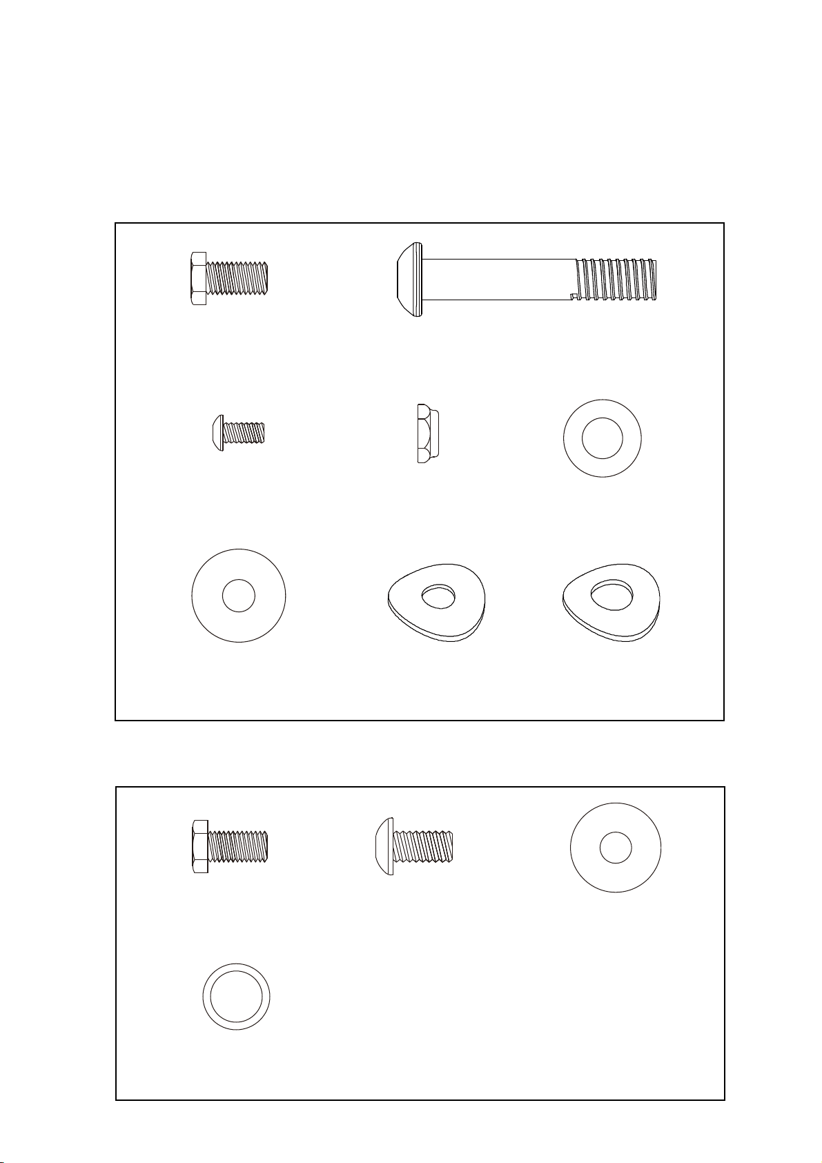
Put t e 4pcs of 5/16"x 23 x1.5T Flat Was ers (125) onto t e 4pcs of 5/16" x 15m/m
Hex Head Bolts (88) and t e 2pcs of 5/16” x 23 x 2T Curved Was ers (129) onto
t e 2pcs of 5/16" x 15m/m Hex Head Bolts (88). Install, and and tig ten by using
t e 12m/m Wrenc (136).
NOTE: T ere is a electrical wire running t roug t e Console Mast Tube (10). Be
careful not to damage or pinc t is Computer Cable (37) during t is procedure.
4. Cut off t e wire tie and separate t e Computer Cable (37) t en plug it in toget er
wit two Handpulse W/Cable Assemblies (41) onto t e bottom of Console
Assembly (36). Secure t e Console Assembly (36) on t e console olding plate
wit 4pcs of M5x10m/m P illips Head Screws (98) by tig tening t em wit
Combination M5 Allen Wrenc & P illips Head Screw Driver (135).
5. Insert two Rail Tubes (17) into t e Frame Base and secure wit 2pcs of 3/8" × 2-
1/4"_Button Head Socket Bolts (97), 2pcs of 3/8" × 19 × 1.5T_Flat Was ers (123)
and 2pcs of 3/8" × 7T_Nyloc Nuts (115) by using 13.14m/m_Wrenc (137) and
Combination M5 Allen Wrenc & P illips Head Screw Driver (135).
6. Lay Rail Assembly (13) between Rail Tubes(17), and secure wit 4pcs of 3/8" × 2-
1/4"_Button Head Socket Bolts (97) and 4pcs of 3/8" × 23 × 2T Curved Was ers
(130) by using Combination M5 Allen Wrenc & P illips Head Screw Driver (135).
6

7

2ANDLE BAR ASSEMBLING
1. Put two Ø17_Wave Was ers (132), Lower Handle Bar (L) (4) and Lower Handle Bar
(R) (5) in order onto t e s aft of Mast (10) and secure wit two 5/16" × 15m/m_Hex
Head Bolts (88) and two 5/16" × 23 × 1.5T_Flat Was ers (125) by using
12m/m_Wrenc (136).
2. Connect Swing Arm (L) (15) wit Lower Handle Bar (L) (4) and secure wit t ree
5/16" × 15m/m_Button Head Socket Bolts (94) by using Combination M5 Allen
Wrenc & P illips Head Screw Driver (135). Repeat t e same procedure for t e
rig t side.
8

3CONNECTING ARM ASSEMBLING
1. Use one 5/16" × 32m/m_Hex Head Bolt (89), 5/16" × 20 × 1.5T_Flat Was er (126) and
5/16" × 7T_Nyloc Nut (114) to secure t e Rod End Bearing(26), w ic is at t e end of
Lower Handle Bar (L) (4), by using 13.14m/m_Wrenc (137) and 12m/m_Wrenc
(136). Repeat t e procedure for t e rig t side.
2. Use 3/8" × 2"_Button Head Socket Bolt (96), 3/8" × 19 × 1.5T_Flat Was er (123) and
3/8" × 7T_Nyloc Nut (115) to secure Outer Slide (14) on t e mainframe by using
13.14m/m_Wrenc (137) and Combination M5 Allen Wrenc & P illips Head Screw
Driver (135). T en use 3/8" × 1-1/2"_Button Head Socket Bolt (95), 3/8" × 19 ×
1.5T_Flat Was er (123) and 3/8" × 7T_Nyloc Nut (115) to secure Inner Slide (18) to
Rail Assembly (13) by using 13.14m/m_Wrenc (137) and Combination M5 Allen
9

Wrenc & P illips Head Screw Driver (135).
4PLASTICS PARTS ASSEMBLING
1. To assemble Connecting Arm Cover (L) (67) and Connecting Arm Cover (R) (68)
onto Lower Handle Bars (4, 5) at eac side, use four M5 × 15m/m_P illips Head
Screws (100) to secure by using Combination M5 Allen Wrenc & P illips Head
Screw Driver (135).
2. To assemble Slide W eel Covers (60) onto left and rig t Pedal Arms (2, 3), use four
M5 × 15m/m_P illips Head Screws (100) to secure by using Combination M5 Allen
Wrenc & P illips Head Screw Driver (135).
3. Use t ree Ø3.5 × 12m/m_S eet Metal Screws (106) to secure Front Handle Bar
Cover (L) (62) and Rear Handle Bar Cover (L) (63) wit Combination M5 Allen
Wrenc & P illips Head Screw Driver (135) onto t e bearing ousing on Lower
Handle Bar (L) (4). Repeat t e procedure for Front Handle Bar Cover (R) (64) and
Rear Handle Bar Cover (R) (65) for t e rig t side.
4. Use two M5 × 15m/m_P illips Head Screws (100) to secure Middle Stabilizer Covers
(69) on rear stabilizer and at eac side of t e mainframe wit Combination M5 Allen
10

Wrenc & P illips Head Screw Driver (135).
5. Use one M5 × 15m/m_P illips Head Screw (100) to secure Rear Stabilizer Cover (L)
(70) on t e Rail Tube wit Combination M5 Allen Wrenc & P illips Head Screw
Driver (135). Repeat t e procedure for Rear Stabilizer Cover (R) (71) for t e ot er
side.
11

LUBRICATION
1. Pour 2c.c of t e lubricant under t e middle of Rail. You must be pour lubricant eac
t ree mont s.
2. If t e user felt t e exercise is not smoot or t ere were some noise during exercising,
please pour 2 c.c.of t e lubricant on t e middle of Rails.
TRANSPORT
T e elliptical is equipped wit two transport w eels w ic are engaged w en rear of it is
lifted.
12

Folding
Step1.
1 . Pull up t e ook from Hook Fixing Block.
2. Grip Slide W eel Cover wit one and, pull up t e ook wit t e ot er and ook it on t e
notc of Hook Hanging Cap, as s own in t e box.
Step2.
1 .Pull up t e ook from Hook Fixing Block.
2 .Grip Slide W eel Cover wit one and, pull up t e ook wit t e ot er and ook it on t e
notc of Hook Hanging Cap, as s own in t e box.
13

Step 3
1. Turn t e Locking Knob counterclockwise.
2. Pull t e knob outward to unlock.
3. Pull up Rail Assembly until locking it up on t e knob t en turn t e knob clockwise until it is
tig t.
Step 4. Finis ing folding.
14

Unfolding
Step 1.
1. Turn t e Locking Knob counterclockwise to release.
2. Pull t e knob outward to unlock.
3. Unfold t e Rail Assembly downward until locking t e knob t en turn t e knob clockwise to
tig ten.
Step 2
1. Hook it on t e notc of t e Hook anging Cap as s own in t e box.
2. Grip t e Slide W eel Cover wit one and, pull up t e Hook wit t e ot er to release t e ook
from t e Hanging Cap and put down t e Slide W eel until it is on t e Rail Assembly.
15

Step 3
1.Hang t e ook on Hook Fixing Block.
2.Grip t e Slide W eel Cover wit one and, pull up t e Hook wit t e ot er to release t e ook
from t e Hanging Cap and put down t e Slide W eel until it is on t e Rail Assembly.
Step 4.
Finis ing unfolding.
16

OPERATION OF YOUR CONSOLE
DISPLAY FUNCTIONS :
ITEM DESCRIPTION
TIME .Workout time displayed during exercise.
.Range 0:00 ~ 99:59
SPEED .Workout speed displayed during exercise.
.Range 0.0 ~ 99.9 KM(ML) / H
DISTANCE .Workout distance displayed during exercise.
.Range 0.0 ~ 99.9 KM/ML
CALORIES .Burned calories during workout display.
.Range 0 ~ 9999
PULSE .Pulse bpm displayed during exercise.
.Pulse alarm w en over preset target pulse.
RPM .Rotation per minute
.Range 0 ~ 999
WATT .Workout power consumption
.Range 0 ~ 999
. In Watt constant mode, computer will remain preset watt value (setting range
0~350)
MANUAL .Manual mode workout.
17

BEGINNER .4 PROGRAM selection.
ADVANCE .4 PROGRAM selection.
SPORTY .4 PROGRAM selection.
WATT
PROGRAM
.WATT constant training mode.
CARDIO .Target HR training mode.
KEY FUNCTION:
OPERATION:
POWER ON
Plug in power supply, computer will power on and display all segments on LCD for 2 seconds.
After 4 minutes wit out pedaling or pulse input, console will enter into power saving mode.
Press any key may wake t e console up.
WORKOUT SELECTION
Press UP and Down to select workout Manual Beginner Advance Sporty
Cardio Watt
18
ITEM DESCRIPTION
UP . Increase resistance level
. Setting selection.
DOWN . Decrease resistance level
. Setting selection.
MODE . Confirm setting or selection.
RESET . Hold on pressing for 2 seconds, computer will reboot and start from user setting.
. Reverse to main menu during presetting workout value or stop mode.
START/ STOP . Start or Stop workout.
RECOVERY . Test eart rate recovery status.
BODY FAT . Test body fat% and BMI.

Manual Mode
Press START in main menu may start workout in
manual mode.
1. Press UP or DOWN to select workout program,
c oose Manual and press Mode to enter.
2. Press UP or DOWN to preset TIME, DISTANCE,
CALORIES, PULSE and press MODE to confirm.
3. Press START/STOP keys to start workout.
Press UP or DOWN to adjust load level.
4. Press START/STOP keys to pause workout.
Press RESET to reverse to main menu.
19

Beginner Mode
1. Press UP or DOWN to select workout program,
c oose Beginner mode and press Mode to enter.
2. Press UP or DOWN to preset TIME.
3. Press START/STOP key to start workout.
Press UP or DOWN to adjust load level.
4. Press START/STOP key to pause workout.
Press RESET to reverse to main menu.
Advance Mode
1. Press UP or DOWN to select workout program,
c oose Advance mode and press Mode to enter.
2. Press UP or DOWN to preset TIME.
3. Press START/STOP key to start workout.
Press UP or DOWN to adjust load level.
4. Press START/STOP key to pause workout.
Press RESET to reverse to main menu.
Sporty Mode
1. Press UP or DOWN to select workout program,
c oose Sporty mode and press Mode to enter.
2. Press UP or DOWN to preset TIME.
3. Press START/STOP key to start workout.
Press UP or DOWN to adjust load level.
4. Press START/STOP key to pause workout.
Press RESET to reverse to main menu.
Cardio Mode
1. Press UP or DOWN to select workout program, c oose H.R.C. and press Mode to enter.
2. Press UP or Down to select 55%.75%.90% or TAG (TARGET H.R.) (default: 100).
3. Press UP or DOWN to preset workout TIME.
16
Table of contents
Other TOORX Elliptical Trainer manuals
Popular Elliptical Trainer manuals by other brands

Vision Fitness
Vision Fitness X6600HRT/DA Assembly guide

Horizon Fitness
Horizon Fitness VersaBALL FX user guide

Sunny Health & Fitness
Sunny Health & Fitness SF-E1114 manual

Horizon Fitness
Horizon Fitness ANDES E owner's manual

Exxentric
Exxentric kPulley2 manual

BH FITNESS
BH FITNESS G2383N Instructions for assembly and use