Sesamo PROSWING User manual

Automatic Operator for swinging doors
OPERATING INSTRUCTIONS
PROSWING (m)

PROSWING (M)
Operating instruction
2

3
Index
Technical specifications .................................................................................................. pag. 6
Function Low-energy ...................................................................................................... pag. 6
Warnings for the installer and general safety ................................................................ pag. 7
Recycling and disposal .................................................................................................. pag. 7
Intended use .................................................................................................................. pag. 8
Limit of use .................................................................................................................... pag. 8
Types of arms.................................................................................................................. pag. 9
Arm extensions................................................................................................................ pag. 10
Dimensions...................................................................................................................... pag. 10
Preliminary checks.......................................................................................................... pag.11
Automatism fixing............................................................................................................ pag. 11
Aluminum base holes positioning .................................................................................. pag. 13
Pull arm installation ........................................................................................................ pag. 14
Push arm installation ...................................................................................................... pag. 18
Preliminary checking ...................................................................................................... pag. 21
Wiring power supply ...................................................................................................... pag. 22
Control board Proswing (M) .......................................................................................... pag. 22
Wiring .............................................................................................................................. pag. 23
External peripherals connectors-Input .......................................................................... pag. 24
External peripherals connectors-Output ........................................................................ pag. 25
Dip-switches setting ........................................................................................................ pag.26
Parameters adjustment-display ...................................................................................... pag. 27
Start up............................................................................................................................ pag. 30
Message or errors code.................................................................................................. pag. 31
Operating logics.............................................................................................................. pag. 32
Electric lock selection and setting.................................................................................. pag. 33
PROSWING (M)
3
PROSWING(M)
Operating instruction

4
Operating instruction
PROSWING (M)
Selectors terminal board ................................................................................................ pag. 35
External peripheral power connector(15Vdc) ................................................................ pag. 35
Wiring and use for double Proswing .............................................................................. pag. 36
Inter lock wiring and use ................................................................................................ pag. 39
Installation batteries (OPTIONAL) .................................................................................. pag. 40
Logic switch .................................................................................................................... pag. 42
Connector for PC-Unit connections................................................................................ pag. 42
Delivery modality ............................................................................................................ pag. 42
SESAMO reserves the right to change the technical specifications of the products, even without notice.

Operating instruction
PROSWING (M)
5
Thank you for choosing this product. For best automatism
performance, Sesamo recommends you carefully read and
follow the installation and use instructions found in this
manual. Installation of this automatism must only be perfor-
med by the professionally qualified personnel for whom this
manual is addressed. Any errors during installation may be
harmful to people or things. Packaging material (wood, pla-
stic, cardboard, etc.) should not be scattered in the environ-
ment or left within the reach of children as potential sources
of danger. Every installation phase must be performed in
accordance with the regulations in force and following Good
Technique standards. Before beginning installation make
sure that the product is integral and has not been damaged
during transportation or by poor storage conditions. Before
installing the product make sure that each architectural and
structural element of the entrance (girder fastening surfaces,
casings, guide, etc.) is appropriate and sufficiently robust to
be automated. Conduct a careful risk analysis and make sui-
table modifications to eliminate conveyance, crushing, cut-
ting and hazardous areas in general. Do not install the pro-
duct in environments where gas, steam or inflammable
fumes are present. The manufacturer is not liable for any
neglect of “good technique” or specific regulations in the con-
struction of the casing to be motorised and any collapse of
the same. All automatic entrance safety and protection devi-
ces (photocells, active sensors, etc.) must be installed in
accordance with the regulations and directives in force, with
the completed risk analysis, system type, use, traffic, forces
and inertia in play. Pay careful attention to area where the
following may occur: crushing, cutting, conveyance and any
other type of hazard in general applying, if necessary suita-
ble indications. Indicate the motorised door identification
information on every installation. Make sure that the
upstream electrical system is correctly dimensioned and has
all the opportune protections (circuit breakers and fuses).
Only use original spare parts in maintenance and repairs. Do
not tamper or alter devices in the automatism and all the
safety devices in the control panel for any reason. The
manufacturer is not liable if parts within the automatism are
altered or tampered with or if safety devices other than those
indicated by the manufacturer are used in the system. The
automatism installer must provide the automatic entrance
manager with the use manual and all the information requi-
red for correct use in automatic and manual modes (even for
electronic locking) and in the event of emergency.
Pay careful attention to the messages in this manual that are
marked with the hazard symbol. They can either be warnings
aimed at avoided potential equipment damage or specific
signals of potential hazard to the installer and others.
This device was designed to automate pedestrian swinging
doors. Any other use is considered contrary to the use fore-
seen by the manufacturer who therefore shall not be held lia-
ble.
Machine directive
The installer who motorised a door becomes the automatic
door machine manufacturer according to directive
2006/42/CE and must:
• Arrange the Technical Booklet with the documents indica-
ted in attachment VII of the Machine Directive and keep them
for at least 10 years.
• Draft the CE declaration of conformity according to attach-
ment II-A of the machine directive and provide the use with a
copy.
• Apply the CE markings on the motorised door according to
point 1.7.3 of attachment I of the machine directive.
For more information and for assist installers in applying the
specifications of the directives and of European standards
concerning the safe use of motorised gates/doors consult
the guidelines available on internet at the address
www.sesamo.eu
DECLARATION OF INCORPORATION
(Directive 2006/42/CE, Annex II, part B)
Manufacturer: SESAMO S.R.L.
Address: Str. Gabannone 8/10 -
15030 Terruggia – AL -
ITALY
Declares that the product PROSWING (m)
- is built to be incorporated in a machine to build a machine
considered by Directive 2006/42/CE
- is conform to the essential safety requirements set out in
annex I of the directive with the exclusion of the following
points: 1.2.4.3, 1.2.4.4, 1.3.4, 1.3.5, 1.3.7, 1.3.8.2, 1.4, 1.5.3,
1.5.7, 1.5.14, 1.5.15, 1.5.16
- is conform to the following other CE directives:
2004/108/CE Electromagnetic Compatibility, 2006/95/CE
Low Voltage
- have been applied the following harmonized norms:
EN 60335 - 1 EN 61000 - 6 - 2
EN 50366 EN 61000 - 6 - 3
And also declares that:
- relevant technical documentation has been fulfilled in
accordance with part B of annex VII of the Directive; this
documentation, or part of it, will be transmitted, by post or
mail, in response to a reasonable request by the national
authorities
- the person authorized to compile the relevant technical
documentation is: SESAMO SRL, Strada Gabannone, 8/10 -
15030 Terruggia (AL) - Italy
- the partly completed machinery must not be put into servi-
ce until the final machinery into which it is to be incorporated
has been declared in conformity with the relevant provisions
of the Machinery Directive 2006/42/CE
SESAMO S.R.L. Director
February 2012 ALDO AMERIO

Technical specifications
In the diagram there is the max door weights related with the door widths:
Function LOW-ENERGY
PROSWING (M) can be set in the order to meet requirements of Low-Energy application according DIN 18650 or BS 7036-
4.
In Low-Energy mode safety is ensured by:
- low speed;
- reduced dynamic/static force.
ATTENTION: Installation of safety sensors monitoring opening and/or closing path is an option to consider after risk
assessment evaluation.
Power supply 230V +/- 10% ac 50 Hz
Nominal power 85 W
Nominal motor torque 45 Nm
External device power 12Vdc – 12W max
Emergency battery power 24V 1,3 Ah
Opening time 3 ÷ 6 sec (70 °/s ÷ 20 °/s)
Closing time 4 ÷ 15 sec (40 °/s ÷ 10 °/s)
Max opening angle 110°
Wing dimension 700 ÷ 1400 mm
Working temperature Inside automatsm from -10°C to +50°C
Anti-crushing Automatic traction restriction in presence of obstacles
Weight 10,5 kg approx
Service Intensive
PROSWING (M)
Operating instruction
6

Warnings for the installer and general safety
1) It is important for the safety of the people installing the automatism according to the regulations. A wrong installation or
use of the product might lead to serious damages to people.
2) Read carafully the operating instructions before installing the product.
3) Store the operating instructions for future reference.
4) This automatism has been designed and built exclusively for the use specified in this documentation. Any different use not
stated herain could affect the integrity of the product and/or represent danger situation.
5) SESAMO declines any responsabilty from misuse or different use from which it was intended.
6) Do not install the product in explosive enviroment: the presence of flamabel gases or fumes is a serious safety hazard.
7) SESAMO is not responsible for the failure to comply with the Good Technical construction procedure of the door to be auto-
mated, as well as deformations that may occur to the door when using the same.
8) Before making any service to the product, take off power supply.
9) Instal a bi-polar switch to cut off power supply.
10) Verify functionality of ground wiring.
11) Safety devices (norm EN 12978) protect possible dangerous areas from mechanical risks during movement, as. anticras-
hing, conveying, shearing.
12) For mainteinance use only genuine SESAMO spare parts.
13) Do not modify components that belongs to the whole automatism.
14) The installer must supply end user all the informations in case of manual operating in emergency.
15) End user shall refrain from any attemp to repair or direct intervenction and ask only to qualified personnel.
16) Installation must be done only from a qualified personnel and in full compliance with regulations.
17) Everything not including in this operating instruction manual is not allowed.
18) This operating instructions manual is only intended for qualified personnel.
Recycling and disposal
RECYCLING OF THE AUTOMATISM AND PACKAGING
This product is built with different materials. The major parts (aluminium, plastic, iron,wires) are solid urban waste. They can be
recycled through collection and disposal in authorized centers.
Other components (control boards, etc.) may contain pollutants. They need to be removed and hand over to companies autho-
rized to recover and dispose them.
The packaging (paperboard, plastics etc.) are solid urban waste and they can be disposed of without any problem, simply per-
forming waste collection for recycling.
Before proceding it is always reccomendr to verify local specific norm for disposal.
PLEASE RECYCLE!
7
PROSWING (M)
Operating instruction

Intended use
The device must be used to automate pedestrian swinging door only.
This device is an electro mechanical system that allow to open and close a swinging door using a trasmission arm.
Door is closed through a motor/spring system or only spring while power is off.
Programmable electronic control board allows correct functionning depending on the type of installation.
Limit of use
ATTENTION: Do not exceed door weight and width as shown in the diagram in “technical specification” paragraph.
To each type of arm correspond a different type of jamb dimension: do not exceed this value (see Paragraph “arm installa-
tion”).
This device is intended only for swinging pedestrian door, dry and inside use.
SESAMO shall not be held liable for any other use contrary to the use foreseen.
RIGID PULL ARM ARTICULATED PUSH ARM
MAX JAMB DEPTH [A] -50 ÷ +100 mm
0 ÷ 300 mm
(depending on the type of arm:
standard or long)
DISTANCE FROM THE ALU-
MINIUM BASE AND DOOR
BRACKET [B]
67 ÷ 127 mm 35 ÷ 95 mm
A
B
-50 +100
B
A
300
PROSWING (M)
Operating instruction
8

Types of arm
ATTENTION: For proper positionning, please refer to the paragraph “Arm Installation”.
PULL ARM
The pulling arm can be fitted:
- PULL (it is used when the automatism is installed
on the same side of the door opening).
STANDARD PUSH ARM
The pushing arm can be fitted :
- PUSH (it is used when the automatism is installed
on the opposite side of the door opening).
LONG PUSH ARM
The long push arm can be fitted:
- PUSH (it is used when the automatism is installed
in the opposite side of the door opening).
jamb depth = 0 ÷ 150 mm
jamb depth = 150 ÷ 300 mm
jamb depth = -50 ÷ 100 mm
Fig. 1
Fig. 2
Fig. 3
9
PROSWING (M)
Operating instruction

Dimensions
Arm extensions
ATTENTION: For a correct positionning refer to “arm installation” paragraph.
L=50 mm L=70 mm L=90 mm
Fig. 4
L=30 mm
(standard)
Fig. 5
56
130
664
86
94
17 630 17
PROSWING (M)
Operating instruction
10

Preliminary checks
Before installing the automatism please check:
- verify the installation does not create dangerous situations;
- prearrange proper pipes and counduits for the wires, granting the protection of the same against mechanical dama-
ges;
- the surface where fixing the automatism has to be resistant. Use screws, bolts, etc. adequate to the type of surface;
- the structure of the door has to be strong to hold the weight of the automatism as well the hinges, also check to not
have friction between fixed and mobile parts;
- use proper equipment and tools to install in security and in accordance with the regulations.
Automatism Fixing
REF. DESCRIPTION
ACover fixing screws
BAluminum cover
CControl board fixing screws
DControl board
EGear motor fixing screws
FGear motor
GTransformer fixing screws
HTransformer
IEnd caps fixing screws
LEnd cap opposite transformer side
MEnd cap transformer side
NAluminum base
OBattery group (OPTIONAL)
C
B
C
A
I
M
H
G
E
L
O
F
N
D
Fig. 6
11
PROSWING (M)
Operating instruction
To fix automatism proceed as follows:
1- remove cover (Fig.6 part.B);
2- disconnect all wiring (encoder, switches, transformer, motor) on control board;
3- unscrew the 2 screws (Fig.6 part.C) and remove control board with its support (screws remain between control board and
support);
4- unscrew the 2 screws (Fig.6 part.G) and remove transform;
5- unscrew the 4 screws (Fig.6 part.E) and remove gear motor;
6- unscrew screws (Fig.6 part.I)and remove end caps (Fig.6 part.M ed L);
7- fix aluminium base (Fig.6 part.N) to thre structure following instructions of the following paragraphs, dipending on arm type;
8- reassemble all components but end caps and aluminium cover.
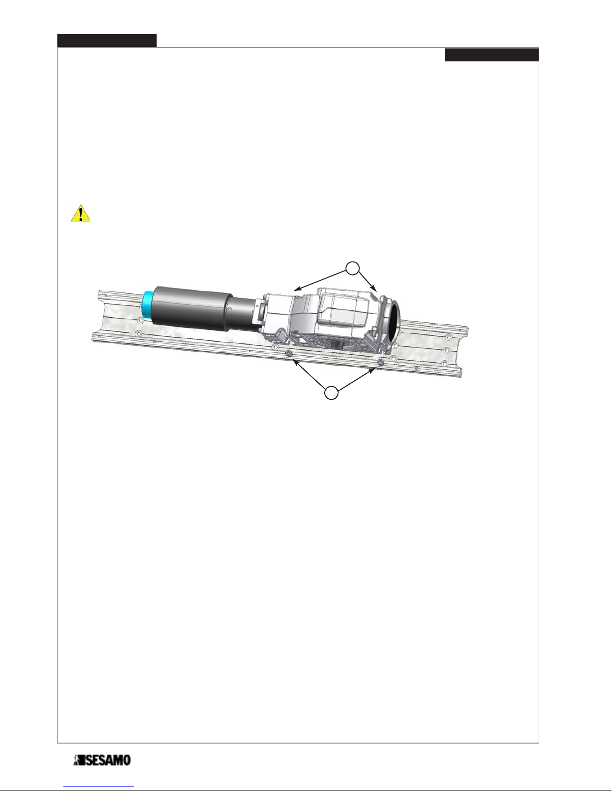
ATTENTION: to make easier reassembling gear motor, partially screw the screws (Fig. 7 part. E), then lean gear motor
on to them. Insert screws (Fig. 7 part. F).
Tight all screws paying attention that gear motor axis is perpendicular to the door top edge.
Fig. 7
E
F
PROSWING (M)
Operating instruction
12

Drilling holes according to the type of screws chosen and fix the base only after verifying the “Positioning dimensions”
listed in the paragraph concerning the type of arm selected.
Fig. 8
With double automatism prearrange the conncetion (wiring) between the two single automatisms.
84
76 88
202
234 30
Aluminum base holes positioning
19,5
19,5 22,5
22,5
Fig. 9
84
76
88 202 23430
19,5
19,5 22,5
22,5
hinge axis
hinge axis
13
PROSWING (M)
Operating instruction
14
Operating instruction
PROSWING (M)
Pull arm installation
Pull arm positioning
Pull arm has to be used when automatism is installed on the same side of door opening.
ATTENTION: For a correct positionning always refer to the hinge axis and gear motor axis, as shown in Fig.10 e 11.
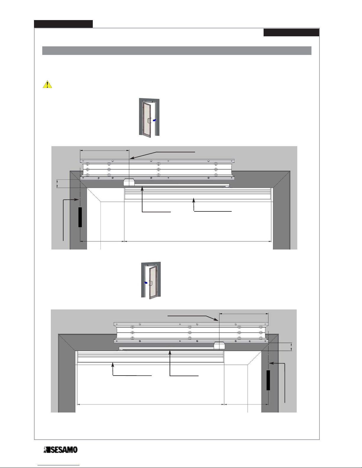
Door opening RIGHT (see Fig. 11)
Door opening LEFT (see Fig. 10)
Fig.10
Hinge axis
Pull arm Sliding guide
Gear motor axis
600
180
C
200
Fig. 11
AHinge axis
Pull arm
Sliding guide
600 180
C
200
Gear motor axis

Operating instruction
PROSWING (M)
15
Sliding guide
Gear motor axis
OPENING
DIRECTION
56
C
ATTENTION: final tightening
of the screws must be performed
only after checking that vertical
positioning of the automatism
allow a good parallelism between
hinge axis and gear motor axis.
Therefore, after fixing the pulling
arm and its guide, the coupling
bolt of the arm with the cylindric
skid have not to create force in
opening/closing cycle.
A positioning error of the automa-
tism might create bending bet-
ween the bolt of the pulling arm
and the cylindric skid more than
the allowed tolerance, damage
parts of the automatism.
32
ARM EXTENSION DIMENSION “C”
Arm extension standard 35
Arm extension (L= 50 mm) 55
Arm extension (L= 70 mm) 75
Arm extension (L= 90 mm) 95
Upper door level
Fig. 12
Jamb depth=-100 mm
Within jamb depth maximum opening angle is proportionally reduced.
Jamb depth=+50 mm

Sliding guide installation
1- Unthread profile (Fig.13 Part.I) and drill 4 holes on the “V” mark on guide profile.
2- Fix guide profile horizontally to the door following dimensions shown in Fig.12.
P
O
I
Fig. 13
4- Insert washer (Fig.14 part.B) and screw (Fig.14 part.C) into arm extension (Fig.14 part.A).
5- Insert arm (Fig.14 part.D) in the arm extension slot, and tight screws (Fig.14 part.E)..
A
B
C
D
E
Fig. 14
PROSWING (M)
Operating instruction
16

6- Insert arm extension (Fig.14 part.A) on the shaft and tight screw (Fig.14 part.C) until arm extension is well fixed to gear motor
shaft.
7- Insert skid (Fig.15 part.G) inside the guide (Fig.15 part.O) and slightly open door.
8- Rotate arm until reaching skid (Fig 15 part. F).
9- Screw skid shaft (Fig.15 part.F) into the arm (Fig.15 part.Q).
10-Insert guide cover profile (Fig.15 part. I)
11-Insert right end cap (Fig.15 part.M) and the left end cap (Fig.15 part.N) onto the guide with their screws (Fig.15 part.L).
I
F
LN
O
P
M
Fig. 15
Q
Verify the dimension about 15 mm (Fig. 16)
Fig. 16
15 mm
17
PROSWING (M)
Operating instruction

Diagram for door opening RIGHT (Fig. 17)
Hinge axis
Door bracket
Motor reducer axis
200
Diagram for door opening LEFT (Fig. 18)
Fig. 17
Hinge axis
Door bracket
Motor reducer axis
200
Fig. 18
Push arm installation
Push arm is used when automatism is installed on the opposite side of door opening.
ATTENTION: For a correct positionning always refer to the hinge axis and gear motor axis, as shown in Fig.17 e 18.
PROSWING(M)
Operating instruction
18

Operating instruction
PROSWING(M)
19
272.5
55
Hinge axis
Door bracket
Fig. 19
35
ARM EXTENSION DIMENSION “E”
Arm extension standard 8
Arm extension (L= 50 mm) 28
Arm extension (L= 70 mm) 48
Arm extension (L= 90 mm) 68
Fig. 20
OPENING
DIRECTION
Push arm
Door bracket
56
Motor axis
Jamb lower edge
ATTENTION: final tightening of the screws must be perfored only after checking arm can easily rotate under door
jamb (Fig.20).
E
Increasing jamb depth, maximum opening angle is proportionally reduced.
25
Jamb depth=0÷300 mm

For PUSH ARM proceed as follows:
1- Insert washer (Fig.21 part.B) and screw (Fig.21 part.C) into arm extension (Fig.21 part.A).
2- Insert arm (Fig.21 part.D) in the arm extension slot, as show in Fig. 21 and tighten screws (Fig.24 part.E).
3- Unscrew screws M8 x 16 (Fig.21 part.G).
4- Fix door bracket (Fig.24 part.F) to the door following dimension shown in Fig. 19 e 20.
5- Insert arm extension (Fig.21 part.A) into gear motor shaft.
6- Tight screw (Fig.21 part.C) until arm extension (part 1) is well fixed to gear motor shaft.
7- Keeping door closed, rotate arm as show in Fig. 22 and tight screws M8 x 16 (Fig. 21 Part. G).
Fig. 21
A
B
C
ED
F
G
Fig. 22
Fix PUSH ARM to the door
PROSWING(M)
Operating instruction
20
Other manuals for PROSWING
1
This manual suits for next models
1
Table of contents
Other Sesamo Door Opening System manuals

Sesamo
Sesamo Digidor User manual

Sesamo
Sesamo PROSWING User manual

Sesamo
Sesamo SwinGo User manual

Sesamo
Sesamo Puma Millenium User manual

Sesamo
Sesamo Roto K3 User manual

Sesamo
Sesamo Digidor User manual

Sesamo
Sesamo PROSWING R Simple manual

Sesamo
Sesamo MILLENNIUM SERIES Operating instructions

Sesamo
Sesamo PIUMA User manual

Sesamo
Sesamo smart PRO User manual


