Toro T7 Series User manual

To adjust the right stop, insert tool blade into cap. Turn blade left to decrease arc; right to increase arc.
To adjust the spray arc:
T7 Series Rotor User’s Guide
The fixed left stop is indicated by the arrow on the sprinkler cap. Align the fixed stop to the left border by turning the sprinkler body.
The right stop is adjustable from 40º–360º.
To position the left stop:
Left stop adjusted to
the left watering border.
Spray arc can be decreased down to 40º. Spray arc can be increased up to 360º.
180
Left Stop
Indicator
Left Stop
Indicator
Right stop increased to match the right watering border.
225

To pull the nozzle riser up:
1. Insert plastic end of
tool into cap.
2. Twist 1/4 turn.
3. Pull nozzle riser up.
To change the nozzle/diffuse spray:
1. Insert tool blade into cap.
2. Retract nozzle screw to release nozzle.
3. Insert tool blade between nozzle lip and
turret to slide nozzle out.
4. Insert new nozzle, and return nozzle
screw to its original depth.
5. To shorten and diffuse spray, increase
nozzle screw depth into stream.
T7 “Low Flow” Nozzle Performance
The T7 is equipped
with a two-way
check valve. To
eliminate check
valve function, install
the check valve disk
in position B.
The check valve is factory
installed in position A.
©2017 The Toro Company, Irrigation Division
www.toro.com
Form Number 373-0559 Rev. G
To install the check valve:
T7 Standard Nozzle Performance
Nozzle Pressure
PSI
Radius
Ft.
Flow
GPM
Precip.
in/hr tri
Precip.
in/hr sq.
Pressure
Bar
Radius
M
Flow
LPM
7.0 40
50
60
70
80
90
100
46
47
48
49
51
52
54
6.6
7.4
8.1
8.8
9.4
10.3
10.7
0.72
0.75
0.78
0.82
0.83
0.85
0.83
0.62
0.65
0.68
0.71
0.72
0.73
0.72
2,8
3,4
4,1
4,8
5,5
6,2
6,9
14,0
14,3
14,6
14,9
15,5
15,8
16,5
25,0
28,0
30,7
33,3
35,6
39,0
40,5
9.0 40
50
60
70
80
90
100
47
50
51
52
54
55
56
7.4
8.3
8.7
9.4
9.9
10.9
11.5
0.76
0.73
0.76
0.81
0.80
0.82
0.84
0.66
0.64
0.66
0.70
0.69
0.71
0.73
2,8
3.4
4,1
4,8
5,5
6,2
6,9
14,3
15,2
15,5
15,8
16,5
16,8
17,1
28,0
31,4
32,9
35,6
37,5
41,3
43,5
12.0 40
50
60
70
80
90
100
50
51
53
54
55
56
57
9.5
11.6
12.7
13.8
14.7
15.6
16.5
0.89
0.90
0.91
0.96
0.99
1.02
1.04
0.77
0.78
0.79
0.83
0.86
0.88
0.90
2,8
3,4
4,1
4,8
5,5
6,2
6,9
15,2
15,5
16,2
16,5
16,8
17,1
17,4
36,0
43,9
48,1
52,2
55,6
59,0
62,5
16.0 40
50
60
70
80
90
100
53
56
58
59
61
62
63
13.0
15.1
16.2
17.5
18.8
20.0
21.1
1.06
1.06
1.04
1.09
1.10
1.14
1.17
0.92
0.92
0.90
0.95
0.95
0.98
1.01
2,8
3,4
4,1
4,8
5,5
6,2
6,9
16,2
17,1
17,7
18,0
18,6
18,9
19,2
49,2
57,2
61,3
66,2
71,2
75,7
79,9
20.0 40
50
60
70
80
90
100
53.0
58
60
61
65
66
67
16.0
17.5
19.5
20.6
22.2
23.6
24.8
1.28
1.22
1.21
1.26
1.19
1.23
1.25
1.10
1.05
1.05
1.09
1.03
1.06
1.09
2,8
3,4
4,1
4,8
5,5
6,2
6,9
16,2
17,7
18,3
18,6
19,8
20,1
20,4
60,6
66,2
73,8
78,0
84,0
89,3
93,9
24.0 40
50
60
70
80
90
100
52
60
63
65
67
68
71
15.8
17.5
19.3
20.7
22.3
23.8
25.3
1.27
1.09
1.11
1.14
1.15
1.20
1.16
1.10
0.95
0.96
0.99
1.00
1.04
1.01
2,8
3,4
4,1
4,8
5,5
6,2
6,9
15,8
18,3
19,2
19,8
20,4
20,7
21,6
58,9
66,2
73,1
78,3
84,4
90,1
95,8
27.0 40
50
60
70
80
90
100
55
65
71
72
73
74
75
18.7
23.4
23.6
25.8
27.4
29.1
30.6
1.42
1.16
1.05
1.10
1.14
1.18
1.21
1.23
1.00
0.91
0.95
0.99
1.02
1.05
2,8
3,4
4,1
4,8
5,5
6,2
6,9
16,8
19,8
21,6
21,9
22,3
22,6
22,9
70,8
88,6
89,3
97,7
103,7
110,1
115,8
Nozzle Pressure
PSI
Radius
Ft.
Flow
GPM
Precip.
in/hr tri
Precip.
in/hr sq.
Pressure
Bar
Radius
M
Flow
LPM
2.0 40
50
60
70
80
90
100
39
39
40
40
40
41
41
1.7
2.0
2.2
2.4
2.6
2.7
2.9
0.25
0.29
0.30
0.33
0.35
0.36
0.38
0.22
0.25
0.26
0.28
0.31
0.31
0.33
2,8
3,4
4,1
4,8
5,5
6,2
6,9
11,9
11,9
12,2
12,2
12,2
12,5
12,5
6,4
7,6
8,3
9,1
9,8
10,2
11,0
3.0 40
50
60
70
80
90
100
39
40
41
41
42
42
43
2.4
2.8
3.1
3.4
3.6
3.9
4.1
0.36
0.39
0.41
0.45
0.46
0.47
0.49
0.31
0.33
0.36
0.39
0.40
0.41
0.42
2,8
3,5
4,1
4,8
5,5
6,2
6,9
11,9
12,2
12,5
12,5
12,8
12,8
13,1
9,1
10,6
11,7
12,9
13,6
14,8
15,5
4.5 40
50
60
70
80
90
100
38
41
41
42
42
43
43
4.1
4.7
5.2
5.7
6.1
6.5
6.9
0.63
0.62
0.68
0.71
0.77
0.78
0.83
0.54
0.53
0.59
0.62
0.66
0.68
0.72
2,8
3,5
4,1
4,8
5,5
6,2
6,9
11,6
12.5
12.5
12.8
12.8
13.1
13.1
15,5
17,8
19,7
21,6
23,1
24,6
26,1
6.0 40
50
60
70
80
90
100
43
46
48
49
49
50
50
5.0
5.7
6.3
7.0
7.4
7.9
8.4
0.59
0.59
0.61
0.65
0.68
0.70
0.74
0.51
0.51
0.52
0.57
0.59
0.61
0.64
2,8
3.4
4.1
4.8
5.5
6.2
6.9
13,1
14,0
14,6
14,9
14,9
15,2
15,2
18,9
21,6
23,8
26,5
28,0
29,9
31,8
7.5 40
50
60
70
80
90
100
44
46
48
49
50
50
52
5.8
6.7
7.4
8.0
8.8
9.5
10.0
0.66
0.70
0.71
0.75
0.78
0.84
0.81
0.58
0.60
0.62
0.65
0.67
0.73
0.70
2,8
3,4
4,1
4,8
5,5
6,2
6,9
13,4
14,0
14,6
14,9
15,2
15,2
15,8
22,0
25,4
28,0
30,3
33,3
36,0
37,9
9.0 40
50
60
70
80
90
100
45
49
51
53
55
55
56
7.4
8.5
9.4
10.4
11.3
12.0
12.8
0.81
0.78
0.80
0.83
0.83
0.89
0.90
0.70
0.68
0.70
0.72
0.72
0.77
0.78
2,8
3,4
4,1
4,8
5,5
6,2
6,9
13,7
14,9
15,5
16,2
16,8
16,8
17,1
28,0
32,2
35,6
39,4
42,8
45,4
48,4
Precipitation data shown for 180˚ arc setting.

Para ajustar la posición del tope derecho, introduzca el destornillador en la tapa de la boquilla. Gire el destornillador en el sentido contrario a las agujas del reloj
para disminuir el ángulo y en el otro sentido para aumentarlo.
Cómo ajustar el ángulo de aspersión:
Manual de instrucciones – Aspersor serie T7
La flecha de la tapa del aspersor indica el tope izquierdo fijo. Alinee el tope fijo con el margen izquierdo haciendo girar el cuerpo del aspersor. El tope derecho
se puede mover para conseguir un ángulo de aspersión de 40º a 360º.
Cómo ubicar el tope izquierdo:
Tope izquierdo ajustado con el
margen de aspersión izquierdo.
El ángulo de aspersión puede reducirse hasta 40º. El ángulo de aspersión puede aumentarse hasta
360º.
180
Indicador de tope
izquierdo.
Indicador de tope
izquierdo.
Distancia del tope derecho
aumentada para cubrir
el margen de aspersión
derecho.
225

Cómo sacar la boquilla del aspersor:
Cómo cambiar la boquilla o variar la difusión del chorro:
Especificaciones de la boquilla T7 Bajo Caudal
Especificaciones de la boquilla T7 Standard
Cómo instalar la válvula de retención:
El T7 está equipado con
una válvula de retención
bidireccional. Para evitar
el funcionamiento de
la válvula de retención,
instale el disco de la
válvula en la posición B.
La válvula de retención viene
instalada de fábrica en la posición A.
1. Introduzca el instrumento
en la tapa de la boquilla.
2. Gírelo 1/4 de vuelta.
3. Saque la boquilla.
1. Introdu
zca el destornillador en la tapa de la
boquilla.
2. Saque el tornillo de la boquilla para soltarla.
3. Introduzca el destornillador entre el borde de
la boquilla la torreta para sacar la boquilla.
4. Coloque la nueva boquilla y vuelva a colocar
el tornillo, dejándolo a la misma profundidad
que al principio.
5. Para acortar o difuminar más el chorro, gire
el tornillo en el senti
do de las agujas del reloj.
2.0 40
50
60
70
80
90
100
39
39
40
40
40
41
41
1.7
2.0
2.2
2.4
2.6
2.7
2.9
0.25
0.29
0.30
0.33
0.35
0.36
0.38
0.22
0.25
0.26
0.28
0.31
0.31
0.33
2,8
3,4
4,1
4,8
5,5
6,2
6,9
11,9
11,9
12,2
12,2
12,2
12,5
12,5
6,4
7,6
8,3
9,1
9,8
10,2
11,0
3.0 40
50
60
70
80
90
100
39
40
41
41
42
42
43
2.4
2.8
3.1
3.4
3.6
3.9
4.1
0.36
0.39
0.41
0.45
0.46
0.47
0.49
0.31
0.33
0.36
0.39
0.40
0.41
0.42
2,8
3,5
4,1
4,8
5,5
6,2
6,9
11,9
12,2
12,5
12,5
12,8
12,8
13,1
9,1
10,6
11,7
12,9
13,6
14,8
15,5
4.5 40
50
60
70
80
90
100
38
41
41
42
42
43
43
4.1
4.7
5.2
5.7
6.1
6.5
6.9
0.63
0.62
0.68
0.71
0.77
0.78
0.83
0.54
0.53
0.59
0.62
0.66
0.68
0.72
2,8
3,5
4,1
4,8
5,5
6,2
6,9
11,6
12.5
12.5
12.8
12.8
13.1
13.1
15,5
17,8
19,7
21,6
23,1
24,6
26,1
6.0 40
50
60
70
80
90
100
43
46
48
49
49
50
50
5.0
5.7
6.3
7.0
7.4
7.9
8.4
0.59
0.59
0.61
0.65
0.68
0.70
0.74
0.51
0.51
0.52
0.57
0.59
0.61
0.64
2,8
3.4
4.1
4.8
5.5
6.2
6.9
13,1
14,0
14,6
14,9
14,9
15,2
15,2
18,9
21,6
23,8
26,5
28,0
29,9
31,8
7.5 40
50
60
70
80
90
100
44
46
48
49
50
50
52
5.8
6.7
7.4
8.0
8.8
9.5
10.0
0.66
0.70
0.71
0.75
0.78
0.84
0.81
0.58
0.60
0.62
0.65
0.67
0.73
0.70
2,8
3,4
4,1
4,8
5,5
6,2
6,9
13,4
14,0
14,6
14,9
15,2
15,2
15,8
22,0
25,4
28,0
30,3
33,3
36,0
37,9
9.0 40
50
60
70
80
90
100
45
49
51
53
55
55
56
7.4
8.5
9.4
10.4
11.3
12.0
12.8
0.81
0.78
0.80
0.83
0.83
0.89
0.90
0.70
0.68
0.70
0.72
0.72
0.77
0.78
2,8
3,4
4,1
4,8
5,5
6,2
6,9
13,7
14,9
15,5
16,2
16,8
16,8
17,1
28,0
32,2
35,6
39,4
42,8
45,4
48,4
Datos de precipitación mostrada por 180˚retroarco.
©2017 The Toro Company, Divisi
ó
n de Riego • www.toro.com
Nº de impreso
373-0559 Rev. G
Boquilla Presión
(PSI) Radio
(Ft.) Caudal
(GPM) Precip.
(pulg/hr) Precip.
(pulg/hr) Presión
(Bar) Radio
(M) Caudal
(L/M) Boquilla Presión
(PSI) Radio
(Ft.) Caudal
(GPM) Precip.
(pulg/hr) Precip.
(pulg/hr) Presión
(Bar) Radio
(M) Caudal
(L/M)
7.0 40
50
60
70
80
90
100
46
47
48
49
51
52
54
6.6
7.4
8.1
8.8
9.4
10.3
10.7
0.72
0.75
0.78
0.82
0.83
0.85
0.83
0.62
0.65
0.68
0.71
0.72
0.73
0.72
2,8
3,4
4,1
4,8
5,5
6,2
6,9
14,0
14,3
14,6
14,9
15,5
15,8
16,5
25,0
28,0
30,7
33,3
35,6
39,0
40,5
9.0 40
50
60
70
80
90
100
47
50
51
52
54
55
56
7.4
8.3
8.7
9.4
9.9
10.9
11.5
0.76
0.73
0.76
0.81
0.80
0.82
0.84
0.66
0.64
0.66
0.70
0.69
0.71
0.73
2,8
3.4
4,1
4,8
5,5
6,2
6,9
14,3
15,2
15,5
15,8
16,5
16,8
17,1
28,0
31,4
32,9
35,6
37,5
41,3
43,5
12.0 40
50
60
70
80
90
100
50
51
53
54
55
56
57
9.5
11.6
12.7
13.8
14.7
15.6
16.5
0.89
0.90
0.91
0.96
0.99
1.02
1.04
0.77
0.78
0.79
0.83
0.86
0.88
0.90
2,8
3,4
4,1
4,8
5,5
6,2
6,9
15,2
15,5
16,2
16,5
16,8
17,1
17,4
36,0
43,9
48,1
52,2
55,6
59,0
62,5
16.0 40
50
60
70
80
90
100
53
56
58
59
61
62
63
13.0
15.1
16.2
17.5
18.8
20.0
21.1
1.06
1.06
1.04
1.09
1.10
1.14
1.17
0.92
0.92
0.90
0.95
0.95
0.98
1.01
2,8
3,4
4,1
4,8
5,5
6,2
6,9
16,2
17,1
17,7
18,0
18,6
18,9
19,2
49,2
57,2
61,3
66,2
71,2
75,7
79,9
20.0 40
50
60
70
80
90
100
53.0
58
60
61
65
66
67
16.0
17.5
19.5
20.6
22.2
23.6
24.8
1.28
1.22
1.21
1.26
1.19
1.23
1.25
1.10
1.05
1.05
1.09
1.03
1.06
1.09
2,8
3,4
4,1
4,8
5,5
6,2
6,9
16,2
17,7
18,3
18,6
19,8
20,1
20,4
60,6
66,2
73,8
78,0
84,0
89,3
93,9
24.0 40
50
60
70
80
90
100
52
60
63
65
67
68
71
15.8
17.5
19.3
20.7
22.3
23.8
25.3
1.27
1.09
1.11
1.14
1.15
1.20
1.16
1.10
0.95
0.96
0.99
1.00
1.04
1.01
2,8
3,4
4,1
4,8
5,5
6,2
6,9
15,8
18,3
19,2
19,8
20,4
20,7
21,6
58,9
66,2
73,1
78,3
84,4
90,1
95,8
27.0 40
50
60
70
80
90
100
55
65
71
72
73
74
75
18.7
23.4
23.6
25.8
27.4
29.1
30.6
1.42
1.16
1.05
1.10
1.14
1.18
1.21
1.23
1.00
0.91
0.95
0.99
1.02
1.05
2,8
3,4
4,1
4,8
5,5
6,2
6,9
16,8
19,8
21,6
21,9
22,3
22,6
22,9
70,8
88,6
89,3
97,7
103,7
110,1
115,8

Pour régler la butée droite, insérez la lame de l'outil dans le couvercle. Tournez la lame vers la gauche pour réduire le secteur ou vers la droite pour
l'augmenter.
Pour régler le secteur d'arrosage :
Guide de l'utilisateur des turbines série T7
u
La butée gauche fixe est indiquée par la flèche sur le couvercle de l'arroseur. Alignez la butée gauche fixe sur la bordure gauche en tournant le corps de
l'arroseur. La butée droite est réglable de 40º à 360º.
Pour positionner la butée gauche :
Butée gauche réglée pour la
bordure d'arrosage gauche.
Le secteur d'arrosage peut être réduit jusqu'à
40º.
Le secteur d'arrosage peut être augmenté jusqu'à
360º.
180
Indicateur
de butée
gauche.
Indicateur de
butée gauche.
Butée droite augmentée pour correspondre à la bordure d'arrosage droite.
225

Pour soulever le porte-buse :
1. Insérez l'outil dans le
couvercle.
2. Tournez d’1/4 de tour.
3. Soulevez le porte-buse.
Pour remplacer la buse ou modifier le jet :
1. Insérez la lame de l'outil dans le couvercle.
2. Desserrez la vis brise-jet pour libérer la buse.
3. Insérez la lame de l'outil entre le bord de la buse
et la tourelle pour extraire la buse.
4. Insérez la nouvelle buse et remettez la vis brise-
jet en place à la profondeur originale.
5. Pour raccourcir et diffuser le jet, augmentez la
profondeur de la vis brise-jet.
Performances des turbines T7 Faible Débit Performances des turbines T7 Normal
Pour monter le clapet antiretour :
Le modèle T7 est équipé
d'un clapet antiretour à
deux voies. Pour supprimer
le fonctionnement du clapet
antiretour, placez le disque
à la position B.
Le clapet antiretour est
monté à l'usine à la position A.
Données sur les précipitations pour 180˚arc.
©2017 The Toro Company, Irrigation Divisi
o
n • www.toro.com
Form. numéro
373-0559 Rev. G
Buse Pression
(PSI) Portée
(Ft.) Débit
(GPM) Pluviom.
(po/h) Pluviom.
(po/h) Pression
(Bar) Portée
(M) Débit
(l/min) Buse Pression
(PSI) Portée
(Ft.) Débit
(GPM) Pluviom.
(po/h) Pluviom.
(po/h) Pression
(Bar) Portée
(M) Débit
(l/min)
7.0 40
50
60
70
80
90
100
46
47
48
49
51
52
54
6.6
7.4
8.1
8.8
9.4
10.3
10.7
0.72
0.75
0.78
0.82
0.83
0.85
0.83
0.62
0.65
0.68
0.71
0.72
0.73
0.72
2,8
3,4
4,1
4,8
5,5
6,2
6,9
14,0
14,3
14,6
14,9
15,5
15,8
16,5
25,0
28,0
30,7
33,3
35,6
39,0
40,5
9.0 40
50
60
70
80
90
100
47
50
51
52
54
55
56
7.4
8.3
8.7
9.4
9.9
10.9
11.5
0.76
0.73
0.76
0.81
0.80
0.82
0.84
0.66
0.64
0.66
0.70
0.69
0.71
0.73
2,8
3.4
4,1
4,8
5,5
6,2
6,9
14,3
15,2
15,5
15,8
16,5
16,8
17,1
28,0
31,4
32,9
35,6
37,5
41,3
43,5
12.0 40
50
60
70
80
90
100
50
51
53
54
55
56
57
9.5
11.6
12.7
13.8
14.7
15.6
16.5
0.89
0.90
0.91
0.96
0.99
1.02
1.04
0.77
0.78
0.79
0.83
0.86
0.88
0.90
2,8
3,4
4,1
4,8
5,5
6,2
6,9
15,2
15,5
16,2
16,5
16,8
17,1
17,4
36,0
43,9
48,1
52,2
55,6
59,0
62,5
16.0 40
50
60
70
80
90
100
53
56
58
59
61
62
63
13.0
15.1
16.2
17.5
18.8
20.0
21.1
1.06
1.06
1.04
1.09
1.10
1.14
1.17
0.92
0.92
0.90
0.95
0.95
0.98
1.01
2,8
3,4
4,1
4,8
5,5
6,2
6,9
16,2
17,1
17,7
18,0
18,6
18,9
19,2
49,2
57,2
61,3
66,2
71,2
75,7
79,9
20.0 40
50
60
70
80
90
100
53.0
58
60
61
65
66
67
16.0
17.5
19.5
20.6
22.2
23.6
24.8
1.28
1.22
1.21
1.26
1.19
1.23
1.25
1.10
1.05
1.05
1.09
1.03
1.06
1.09
2,8
3,4
4,1
4,8
5,5
6,2
6,9
16,2
17,7
18,3
18,6
19,8
20,1
20,4
60,6
66,2
73,8
78,0
84,0
89,3
93,9
24.0 40
50
60
70
80
90
100
52
60
63
65
67
68
71
15.8
17.5
19.3
20.7
22.3
23.8
25.3
1.27
1.09
1.11
1.14
1.15
1.20
1.16
1.10
0.95
0.96
0.99
1.00
1.04
1.01
2,8
3,4
4,1
4,8
5,5
6,2
6,9
15,8
18,3
19,2
19,8
20,4
20,7
21,6
58,9
66,2
73,1
78,3
84,4
90,1
95,8
27.0 40
50
60
70
80
90
100
55
65
71
72
73
74
75
18.7
23.4
23.6
25.8
27.4
29.1
30.6
1.42
1.16
1.05
1.10
1.14
1.18
1.21
1.23
1.00
0.91
0.95
0.99
1.02
1.05
2,8
3,4
4,1
4,8
5,5
6,2
6,9
16,8
19,8
21,6
21,9
22,3
22,6
22,9
70,8
88,6
89,3
97,7
103,7
110,1
115,8
2.0 40
50
60
70
80
90
100
39
39
40
40
40
41
41
1.7
2.0
2.2
2.4
2.6
2.7
2.9
0.25
0.29
0.30
0.33
0.35
0.36
0.38
0.22
0.25
0.26
0.28
0.31
0.31
0.33
2,8
3,4
4,1
4,8
5,5
6,2
6,9
11,9
11,9
12,2
12,2
12,2
12,5
12,5
6,4
7,6
8,3
9,1
9,8
10,2
11,0
3.0 40
50
60
70
80
90
100
39
40
41
41
42
42
43
2.4
2.8
3.1
3.4
3.6
3.9
4.1
0.36
0.39
0.41
0.45
0.46
0.47
0.49
0.31
0.33
0.36
0.39
0.40
0.41
0.42
2,8
3,5
4,1
4,8
5,5
6,2
6,9
11,9
12,2
12,5
12,5
12,8
12,8
13,1
9,1
10,6
11,7
12,9
13,6
14,8
15,5
4.5 40
50
60
70
80
90
100
38
41
41
42
42
43
43
4.1
4.7
5.2
5.7
6.1
6.5
6.9
0.63
0.62
0.68
0.71
0.77
0.78
0.83
0.54
0.53
0.59
0.62
0.66
0.68
0.72
2,8
3,5
4,1
4,8
5,5
6,2
6,9
11,6
12.5
12.5
12.8
12.8
13.1
13.1
15,5
17,8
19,7
21,6
23,1
24,6
26,1
6.0 40
50
60
70
80
90
100
43
46
48
49
49
50
50
5.0
5.7
6.3
7.0
7.4
7.9
8.4
0.59
0.59
0.61
0.65
0.68
0.70
0.74
0.51
0.51
0.52
0.57
0.59
0.61
0.64
2,8
3.4
4.1
4.8
5.5
6.2
6.9
13,1
14,0
14,6
14,9
14,9
15,2
15,2
18,9
21,6
23,8
26,5
28,0
29,9
31,8
7.5 40
50
60
70
80
90
100
44
46
48
49
50
50
52
5.8
6.7
7.4
8.0
8.8
9.5
10.0
0.66
0.70
0.71
0.75
0.78
0.84
0.81
0.58
0.60
0.62
0.65
0.67
0.73
0.70
2,8
3,4
4,1
4,8
5,5
6,2
6,9
13,4
14,0
14,6
14,9
15,2
15,2
15,8
22,0
25,4
28,0
30,3
33,3
36,0
37,9
9.0 40
50
60
70
80
90
100
45
49
51
53
55
55
56
7.4
8.5
9.4
10.4
11.3
12.0
12.8
0.81
0.78
0.80
0.83
0.83
0.89
0.90
0.70
0.68
0.70
0.72
0.72
0.77
0.78
2,8
3,4
4,1
4,8
5,5
6,2
6,9
13,7
14,9
15,5
16,2
16,8
16,8
17,1
28,0
32,2
35,6
39,4
42,8
45,4
48,4

Per regolare il fermo destro, inserire la lama dell’utensile nel coprighiera. Girare la lama verso sinistra per ridurre l’arco, o verso destra per
ampliarlo.
Regolazione dell’angolo di lavoro:
Irrigatore Rotor Serie T7 – Guida all’uso
La freccia sul coprighiera indica il fermo fisso a sinistra. Girare il corpo dell’irrigatore fino ad allineare il fermo fisso con il bordo sinistro. Il
fermo destro è regolabile da 40º a 360º.
Posizionamento del fermo sinistro:
Fermo sinistro allineato al bordo
sinistro dell’area da irrigare.
Angolo di lavoro regolabile – min 40º. Angolo di lavoro regolabile – max 360º.
180
Indicatore del
fermo sinistro.
Indicatore del
fermo sinistro.
Aumento del fermo destro
in corrispondenza del bordo
destro dell’area da irrigare.
225

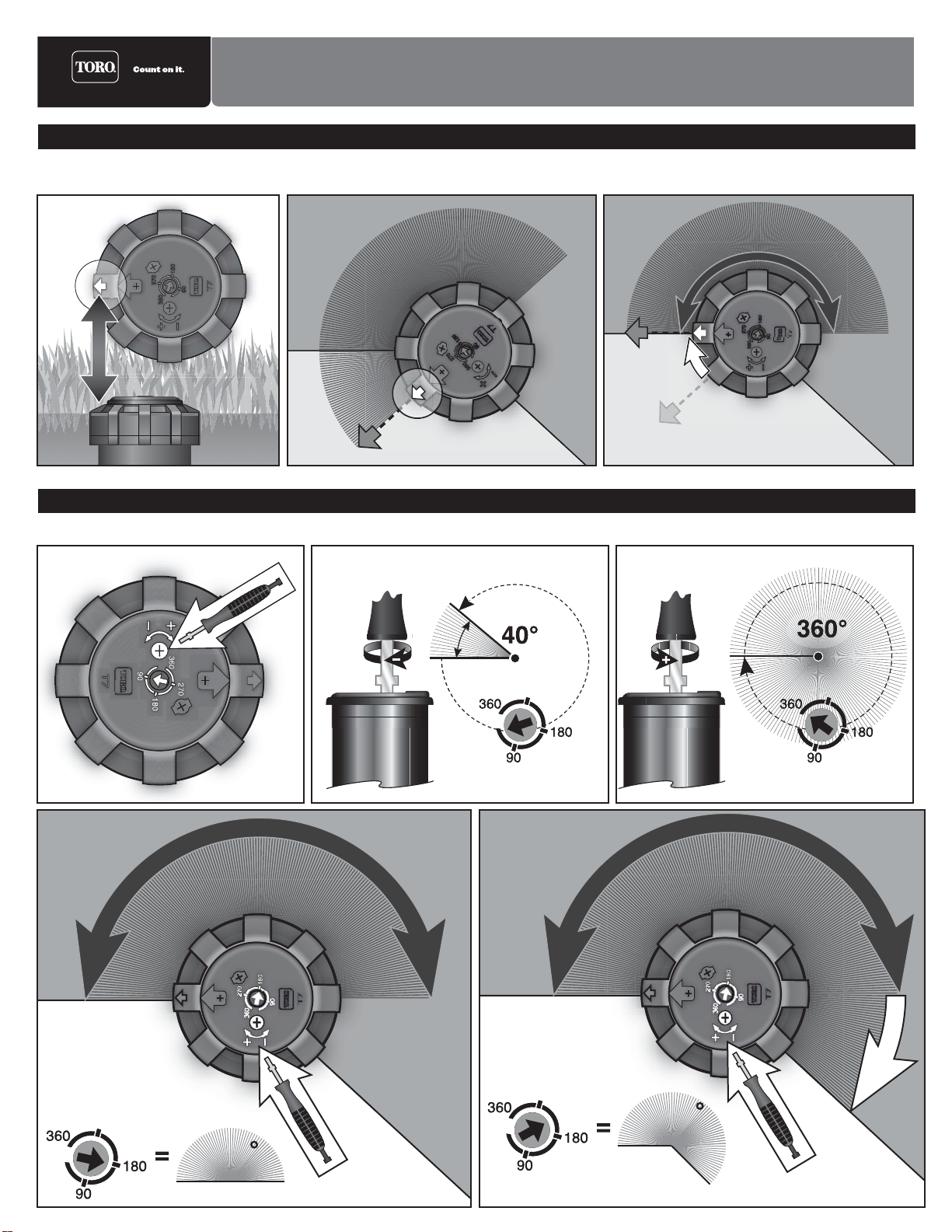
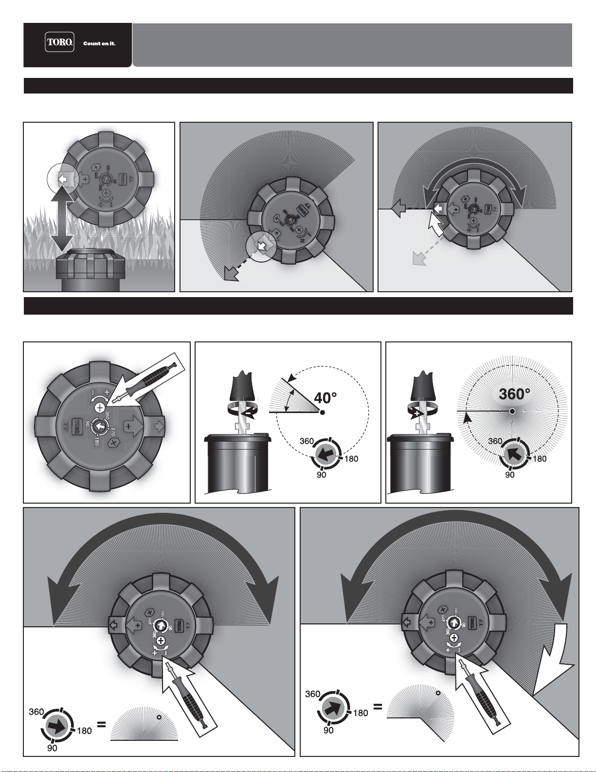
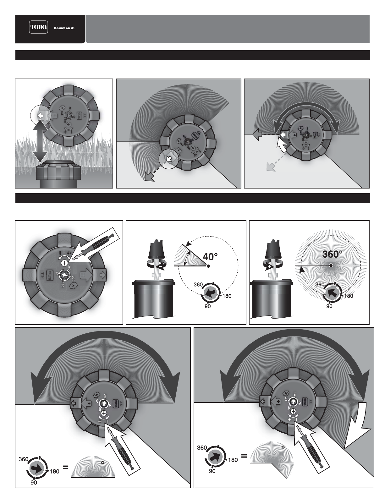
Sollevamento del portaugelli: Cambio di ugello/getto a ventaglio:
Prestazioni degli ugelli T7 Basso Flusso Prestazioni degli ugelli T7 Standard
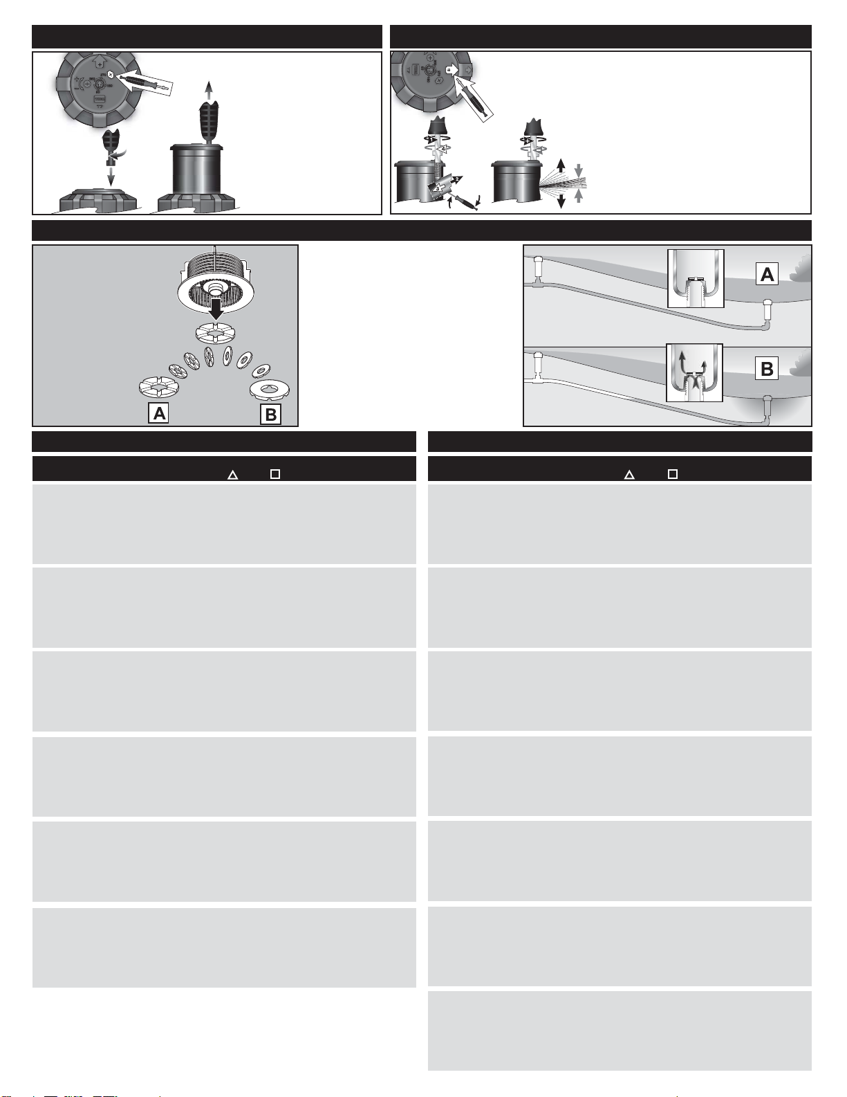
Installazione della valvola di ritenuta:
La serie T7 è dotata di
una valvola di ritenuta a
due vie. Per escludere la
funzione della valvola di
ritenuta, montare il disco
della valvola di ritenuta
nella posizione B. La valvola di ritenuta è
preinstallata in fabbrica nella posizione A.
1. Inserire il utensile nel
coprighiera.
2. Girarla di 1/4 di giro.
3. Sollevare il portaugelli.
1. Inserire la lama dell’utensile nel coprighiera.
2. Svitare la vite dell’ugello per rilasciare
l’ugello.
3. Inserire la lama dell’utensile tra il bordo
dell’ugello e la torretta per estrarre l’ugello.
4. Inserire il nuovo ugello e riavvitare la vite
dell’ugello alla profondità originale.
5. Per ridurre il getto e creare un getto a
ventaglio, avvitare più a fondo nel getto la
vite dell’ugello.
Ugello Pressione
(psi) Gittata
(ft) Portata
(GPM) Precip.
(in/h) Precip.
(in/h) Pressione
(bar) Gittata
(M) Portata
(l/min) Ugello Pressione
(psi) Gittata
(ft) Portata
(GPM) Precip.
(in/h) Precip.
(in/h) Pressione
(bar) Gittata
(M) Portata
(l/min)
Precipitazioni di 180˚arc.
©2017 The Toro Company, Irrigation Divisi
o
n • www.toro.com
Documento n.
373-0559 Rev. G
2.0 40
50
60
70
80
90
100
39
39
40
40
40
41
41
1.7
2.0
2.2
2.4
2.6
2.7
2.9
0.25
0.29
0.30
0.33
0.35
0.36
0.38
0.22
0.25
0.26
0.28
0.31
0.31
0.33
2,8
3,4
4,1
4,8
5,5
6,2
6,9
11,9
11,9
12,2
12,2
12,2
12,5
12,5
6,4
7,6
8,3
9,1
9,8
10,2
11,0
3.0 40
50
60
70
80
90
100
39
40
41
41
42
42
43
2.4
2.8
3.1
3.4
3.6
3.9
4.1
0.36
0.39
0.41
0.45
0.46
0.47
0.49
0.31
0.33
0.36
0.39
0.40
0.41
0.42
2,8
3,5
4,1
4,8
5,5
6,2
6,9
11,9
12,2
12,5
12,5
12,8
12,8
13,1
9,1
10,6
11,7
12,9
13,6
14,8
15,5
4.5 40
50
60
70
80
90
100
38
41
41
42
42
43
43
4.1
4.7
5.2
5.7
6.1
6.5
6.9
0.63
0.62
0.68
0.71
0.77
0.78
0.83
0.54
0.53
0.59
0.62
0.66
0.68
0.72
2,8
3,5
4,1
4,8
5,5
6,2
6,9
11,6
12.5
12.5
12.8
12.8
13.1
13.1
15,5
17,8
19,7
21,6
23,1
24,6
26,1
6.0 40
50
60
70
80
90
100
43
46
48
49
49
50
50
5.0
5.7
6.3
7.0
7.4
7.9
8.4
0.59
0.59
0.61
0.65
0.68
0.70
0.74
0.51
0.51
0.52
0.57
0.59
0.61
0.64
2,8
3.4
4.1
4.8
5.5
6.2
6.9
13,1
14,0
14,6
14,9
14,9
15,2
15,2
18,9
21,6
23,8
26,5
28,0
29,9
31,8
7.5 40
50
60
70
80
90
100
44
46
48
49
50
50
52
5.8
6.7
7.4
8.0
8.8
9.5
10.0
0.66
0.70
0.71
0.75
0.78
0.84
0.81
0.58
0.60
0.62
0.65
0.67
0.73
0.70
2,8
3,4
4,1
4,8
5,5
6,2
6,9
13,4
14,0
14,6
14,9
15,2
15,2
15,8
22,0
25,4
28,0
30,3
33,3
36,0
37,9
9.0 40
50
60
70
80
90
100
45
49
51
53
55
55
56
7.4
8.5
9.4
10.4
11.3
12.0
12.8
0.81
0.78
0.80
0.83
0.83
0.89
0.90
0.70
0.68
0.70
0.72
0.72
0.77
0.78
2,8
3,4
4,1
4,8
5,5
6,2
6,9
13,7
14,9
15,5
16,2
16,8
16,8
17,1
28,0
32,2
35,6
39,4
42,8
45,4
48,4
7.0 40
50
60
70
80
90
100
46
47
48
49
51
52
54
6.6
7.4
8.1
8.8
9.4
10.3
10.7
0.72
0.75
0.78
0.82
0.83
0.85
0.83
0.62
0.65
0.68
0.71
0.72
0.73
0.72
2,8
3,4
4,1
4,8
5,5
6,2
6,9
14,0
14,3
14,6
14,9
15,5
15,8
16,5
25,0
28,0
30,7
33,3
35,6
39,0
40,5
9.0 40
50
60
70
80
90
100
47
50
51
52
54
55
56
7.4
8.3
8.7
9.4
9.9
10.9
11.5
0.76
0.73
0.76
0.81
0.80
0.82
0.84
0.66
0.64
0.66
0.70
0.69
0.71
0.73
2,8
3.4
4,1
4,8
5,5
6,2
6,9
14,3
15,2
15,5
15,8
16,5
16,8
17,1
28,0
31,4
32,9
35,6
37,5
41,3
43,5
12.0 40
50
60
70
80
90
100
50
51
53
54
55
56
57
9.5
11.6
12.7
13.8
14.7
15.6
16.5
0.89
0.90
0.91
0.96
0.99
1.02
1.04
0.77
0.78
0.79
0.83
0.86
0.88
0.90
2,8
3,4
4,1
4,8
5,5
6,2
6,9
15,2
15,5
16,2
16,5
16,8
17,1
17,4
36,0
43,9
48,1
52,2
55,6
59,0
62,5
16.0 40
50
60
70
80
90
100
53
56
58
59
61
62
63
13.0
15.1
16.2
17.5
18.8
20.0
21.1
1.06
1.06
1.04
1.09
1.10
1.14
1.17
0.92
0.92
0.90
0.95
0.95
0.98
1.01
2,8
3,4
4,1
4,8
5,5
6,2
6,9
16,2
17,1
17,7
18,0
18,6
18,9
19,2
49,2
57,2
61,3
66,2
71,2
75,7
79,9
20.0 40
50
60
70
80
90
100
53.0
58
60
61
65
66
67
16.0
17.5
19.5
20.6
22.2
23.6
24.8
1.28
1.22
1.21
1.26
1.19
1.23
1.25
1.10
1.05
1.05
1.09
1.03
1.06
1.09
2,8
3,4
4,1
4,8
5,5
6,2
6,9
16,2
17,7
18,3
18,6
19,8
20,1
20,4
60,6
66,2
73,8
78,0
84,0
89,3
93,9
24.0 40
50
60
70
80
90
100
52
60
63
65
67
68
71
15.8
17.5
19.3
20.7
22.3
23.8
25.3
1.27
1.09
1.11
1.14
1.15
1.20
1.16
1.10
0.95
0.96
0.99
1.00
1.04
1.01
2,8
3,4
4,1
4,8
5,5
6,2
6,9
15,8
18,3
19,2
19,8
20,4
20,7
21,6
58,9
66,2
73,1
78,3
84,4
90,1
95,8
27.0 40
50
60
70
80
90
100
55
65
71
72
73
74
75
18.7
23.4
23.6
25.8
27.4
29.1
30.6
1.42
1.16
1.05
1.10
1.14
1.18
1.21
1.23
1.00
0.91
0.95
0.99
1.02
1.05
2,8
3,4
4,1
4,8
5,5
6,2
6,9
16,8
19,8
21,6
21,9
22,3
22,6
22,9
70,8
88,6
89,3
97,7
103,7
110,1
115,8

Zum Einstellen des rechten Anschlags setzen Sie die Werkzeugklinge in die Kappe. Drehen Sie die Klinge nach links, um den Sektor zu vergrößern und nach
rechts, um ihn zu verkleinern.
So stellen Sie den Sprühsektor ein:
Getrieberegner der Serie T7 – Bedienungsanleitung
Der starre linke Anschlag wird durch den Pfeil auf der Regnerkappe angegeben. Drehen Sie das Regnergehäuse, um den starren Anschlag mit dem linken
Rand auszufluchten. Der rechte Anschlag kann zwischen 40° bis 360° eingestellt werden.
So positionieren Sie den linken Anschlag:
Auf den linken Beregnungsrand eingestellter
linker Anschlag.
Der Sprühsektor kann bis auf 40° verkleinert werden. Der Sprühsektor kann bis auf 360° vergrößert
werden.
180
Anzeige
für linken
Anschlag.
Anzeige für linken
Anschlag.
Der rechte Anschlag
wurde vergrößert,
um dem rechten
Beregnungsrand zu
entsprechen.
225

So ziehen Sie den Düsenaufsteiger hoch: So verstellen Sie den Düsen-/Verteilerstrahl:
T7-Düsenleistung “Low-Flow” T7-Düsenleistung
So installieren Sie das Rückschlagventil:
1. Setzen Sie das Werkzeug
in die Kappe.
2. Eine 1/4 Umdrehung.
3. Ziehen Sie den
Düsenaufsteiger
hoch.
1. Stecken Sie die Werkzeugklinge in die Kappe.
2. Drehen Sie die Düsenschraube heraus, um
die Düse zu lösen.
3. Setzen Sie die Werkzeugklinge zwischen die
Düsenlippe und den Abwurfwinkel ein und
schieben Sie die Düse heraus.
4. Setzen Sie die neue Düse ein und schrauben
Sie die Düsenschraube bis auf die
Originalstellung ein.
5. Zum Verkürzen und Verteilen des
Spritzstrahl schrauben Sie die
Düsenschraube weiter in den Strom hinein.
Der T7 ist mit einem
wechselseitigen
Rückschlagventil
ausgestattet. Installieren Sie
die Rückschlagventilscheibe
in Stellung B, wenn Sie die
Rückschlagventil-Funktion
ausschalten möchten.
Das Rückschlagventil wird
werksseitig in Stellung A installiert.
Niederschlagsdaten für 180˚Bogen Einstellung gezeigt.
©2017 The Toro Company, Irrigation Divisi
o
n • www.toro.com
Formularnummer
373-0559 Rev. G
Düse Druck
(PSI) Wurfweite
(Fuß) Fluss
(GPM) Niederschlag
(po/h) Niederschlag
(po/h) Druck
(Bar) Wurfweite
(M) Fluss
(l/min) Düse Druck
(PSI) Wurfweite
(Fuß) Fluss
(GPM) Niederschlag
(po/h) Niederschlag
(po/h) Druck
(Bar) Wurfweite
(M) Fluss
(l/min)
7.0 40
50
60
70
80
90
100
46
47
48
49
51
52
54
6.6
7.4
8.1
8.8
9.4
10.3
10.7
0.72
0.75
0.78
0.82
0.83
0.85
0.83
0.62
0.65
0.68
0.71
0.72
0.73
0.72
2,8
3,4
4,1
4,8
5,5
6,2
6,9
14,0
14,3
14,6
14,9
15,5
15,8
16,5
25,0
28,0
30,7
33,3
35,6
39,0
40,5
9.0 40
50
60
70
80
90
100
47
50
51
52
54
55
56
7.4
8.3
8.7
9.4
9.9
10.9
11.5
0.76
0.73
0.76
0.81
0.80
0.82
0.84
0.66
0.64
0.66
0.70
0.69
0.71
0.73
2,8
3.4
4,1
4,8
5,5
6,2
6,9
14,3
15,2
15,5
15,8
16,5
16,8
17,1
28,0
31,4
32,9
35,6
37,5
41,3
43,5
12.0 40
50
60
70
80
90
100
50
51
53
54
55
56
57
9.5
11.6
12.7
13.8
14.7
15.6
16.5
0.89
0.90
0.91
0.96
0.99
1.02
1.04
0.77
0.78
0.79
0.83
0.86
0.88
0.90
2,8
3,4
4,1
4,8
5,5
6,2
6,9
15,2
15,5
16,2
16,5
16,8
17,1
17,4
36,0
43,9
48,1
52,2
55,6
59,0
62,5
16.0 40
50
60
70
80
90
100
53
56
58
59
61
62
63
13.0
15.1
16.2
17.5
18.8
20.0
21.1
1.06
1.06
1.04
1.09
1.10
1.14
1.17
0.92
0.92
0.90
0.95
0.95
0.98
1.01
2,8
3,4
4,1
4,8
5,5
6,2
6,9
16,2
17,1
17,7
18,0
18,6
18,9
19,2
49,2
57,2
61,3
66,2
71,2
75,7
79,9
20.0 40
50
60
70
80
90
100
53.0
58
60
61
65
66
67
16.0
17.5
19.5
20.6
22.2
23.6
24.8
1.28
1.22
1.21
1.26
1.19
1.23
1.25
1.10
1.05
1.05
1.09
1.03
1.06
1.09
2,8
3,4
4,1
4,8
5,5
6,2
6,9
16,2
17,7
18,3
18,6
19,8
20,1
20,4
60,6
66,2
73,8
78,0
84,0
89,3
93,9
24.0 40
50
60
70
80
90
100
52
60
63
65
67
68
71
15.8
17.5
19.3
20.7
22.3
23.8
25.3
1.27
1.09
1.11
1.14
1.15
1.20
1.16
1.10
0.95
0.96
0.99
1.00
1.04
1.01
2,8
3,4
4,1
4,8
5,5
6,2
6,9
15,8
18,3
19,2
19,8
20,4
20,7
21,6
58,9
66,2
73,1
78,3
84,4
90,1
95,8
27.0 40
50
60
70
80
90
100
55
65
71
72
73
74
75
18.7
23.4
23.6
25.8
27.4
29.1
30.6
1.42
1.16
1.05
1.10
1.14
1.18
1.21
1.23
1.00
0.91
0.95
0.99
1.02
1.05
2,8
3,4
4,1
4,8
5,5
6,2
6,9
16,8
19,8
21,6
21,9
22,3
22,6
22,9
70,8
88,6
89,3
97,7
103,7
110,1
115,8
2.0 40
50
60
70
80
90
100
39
39
40
40
40
41
41
1.7
2.0
2.2
2.4
2.6
2.7
2.9
0.25
0.29
0.30
0.33
0.35
0.36
0.38
0.22
0.25
0.26
0.28
0.31
0.31
0.33
2,8
3,4
4,1
4,8
5,5
6,2
6,9
11,9
11,9
12,2
12,2
12,2
12,5
12,5
6,4
7,6
8,3
9,1
9,8
10,2
11,0
3.0 40
50
60
70
80
90
100
39
40
41
41
42
42
43
2.4
2.8
3.1
3.4
3.6
3.9
4.1
0.36
0.39
0.41
0.45
0.46
0.47
0.49
0.31
0.33
0.36
0.39
0.40
0.41
0.42
2,8
3,5
4,1
4,8
5,5
6,2
6,9
11,9
12,2
12,5
12,5
12,8
12,8
13,1
9,1
10,6
11,7
12,9
13,6
14,8
15,5
4.5 40
50
60
70
80
90
100
38
41
41
42
42
43
43
4.1
4.7
5.2
5.7
6.1
6.5
6.9
0.63
0.62
0.68
0.71
0.77
0.78
0.83
0.54
0.53
0.59
0.62
0.66
0.68
0.72
2,8
3,5
4,1
4,8
5,5
6,2
6,9
11,6
12.5
12.5
12.8
12.8
13.1
13.1
15,5
17,8
19,7
21,6
23,1
24,6
26,1
6.0 40
50
60
70
80
90
100
43
46
48
49
49
50
50
5.0
5.7
6.3
7.0
7.4
7.9
8.4
0.59
0.59
0.61
0.65
0.68
0.70
0.74
0.51
0.51
0.52
0.57
0.59
0.61
0.64
2,8
3.4
4.1
4.8
5.5
6.2
6.9
13,1
14,0
14,6
14,9
14,9
15,2
15,2
18,9
21,6
23,8
26,5
28,0
29,9
31,8
7.5 40
50
60
70
80
90
100
44
46
48
49
50
50
52
5.8
6.7
7.4
8.0
8.8
9.5
10.0
0.66
0.70
0.71
0.75
0.78
0.84
0.81
0.58
0.60
0.62
0.65
0.67
0.73
0.70
2,8
3,4
4,1
4,8
5,5
6,2
6,9
13,4
14,0
14,6
14,9
15,2
15,2
15,8
22,0
25,4
28,0
30,3
33,3
36,0
37,9
9.0 40
50
60
70
80
90
100
45
49
51
53
55
55
56
7.4
8.5
9.4
10.4
11.3
12.0
12.8
0.81
0.78
0.80
0.83
0.83
0.89
0.90
0.70
0.68
0.70
0.72
0.72
0.77
0.78
2,8
3,4
4,1
4,8
5,5
6,2
6,9
13,7
14,9
15,5
16,2
16,8
16,8
17,1
28,0
32,2
35,6
39,4
42,8
45,4
48,4
Other manuals for T7 Series
2
Table of contents
Languages:
Other Toro Lawn And Garden Equipment manuals

Toro
Toro 07356 User manual

Toro
Toro Wheel Horse 79375 User manual

Toro
Toro 22368 User manual

Toro
Toro Shovel 31803T User manual

Toro
Toro ECx User manual

Toro
Toro 125-5180 User manual

Toro
Toro Leaf Cart User manual

Toro
Toro eS3000SD 72V User manual

Toro
Toro Groundsmaster 3320 Series User manual

Toro
Toro 133-2861 User manual

Toro
Toro 22980 User manual

Toro
Toro TRX-20 User manual

Toro
Toro 66205T User manual

Toro
Toro 58630 User manual

Toro
Toro GreensPro 1240 User manual

Toro
Toro 136-3860 User manual

Toro
Toro Ultra Buggy 2500-T User manual

Toro
Toro Flex-Force Power System 88714 User manual

Toro
Toro 03662 User manual

Toro
Toro Bullseye NuSurface 470 User manual