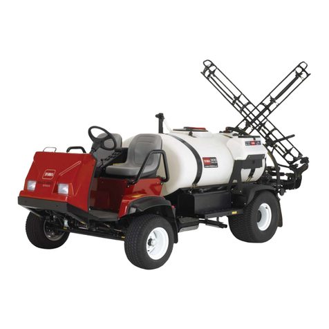
Toro Ultra Sonic Boom 41219 User manual

FormNo.3385-426RevA
UltraSonicBoom™LevelingKit
2013andAfterMulti-Pro5800,1750andWMTurfSprayers
ModelNo.41219—SerialNo.314000001andUp
InstallationInstructions
Thisattachmentmaintainsconsistentdistancesfromtheboomnozzlestothegroundwhen
sprayingoverunevensurfacesandisintendedtobeusedbyprofessional,hiredoperatorsin
commercialapplications.Itisprimarilydesignedforsprayinggolfcourseapplications,parks,
sportselds,andoncommercialgrounds.Itisdesignedtoonlybeusedinconjunctionwith
machinesdesignatedbythemanufacturer.
ThisproductcomplieswithallrelevantEuropeandirectives.Fordetails,pleaseseethe
separateproductspecicDeclarationofConformity(DOC)sheet.
WARNING
CALIFORNIA
Proposition65Warning
Thisproductcontainsachemicalorchemicals
knowntotheStateofCaliforniatocausecancer,
birthdefects,orreproductiveharm.
Useofthisproductmaycauseexposureto
chemicalsknowntotheStateofCalifornia
tocausecancer,birthdefects,orother
reproductiveharm.
©2014—TheToro®Company
8111LyndaleAvenueSouth
Bloomington,MN55420
Registeratwww.T oro.com.OriginalInstructions(EN)
PrintedintheUSA
AllRightsReserved*3385-426*A

Installation
LooseParts
Usethechartbelowtoverifythatallpartshavebeenshipped.
ProcedureDescriptionQty.Use
1Nopartsrequired–Preparethemachine.
Hinge2
Angledstrap(foranuncoveredboom)2
Angledstrap(foracoveredboom)2
Toporbottomstrap2
Compressionspring4
Bushing8
Hex-headbolt(5/16x3-1/4inch)4
Flatwasher12
2
Locknut(5/16inch)4
Assemblethesensormounting
hardware.
Hydraulicmanifoldblock1
3Hydraulictting4Preparethebooms.
Boomcradlearm2
4Caps2Replacetheboomcradlearms.
Sonicboomsensor2
Bracket2
Programmingplug2
Sensorcover2
Lowersensorhousing2
Captube2
Sensorguardbracket2
Sensorcable(4m)2
Largenut4
U-bolt6
Locknut(1/4inch)8
Bolt(5/16x3/4inch)8
Bolt(5/16x1-1/4inch)4
Locknut(5/16inch)12
5
Cabletie12
Installthesonicboomsensors.
Electroniccontroller1
Mountingbracket1
Bolt(1/4x1-1/8inch)4
6Locknut(1/4inch)4
Mounttheelectroniccontrols.
Wiringharness1
Rockerswitch1
Indicatorlight1
7Cabletie12
Installthecontrols.
8Nopartsrequired–Calibratethesonicbooms.
Important:Inordertocompletetheinstallation,youmustpurchaseaseparatenishingkit.FortheMulti-Pro
5800,ordernishingkit130-8229.FortheMulti-Pro1750,ordernishingkit130-8227.FortheMulti-ProWM,
ordernishingkit130-8228.
Note:Determinetheleftandrightsidesofthemachinefromthenormaloperatingposition.
2

1
PreparingtheMachine
NoPartsRequired
Procedure
Positionthemachineonalevelsurface,stoptheengine,
removetheignitionkey,andengagetheparkingbrake.
CAUTION
Ifyouleavethekeyintheignitionswitch,someone
couldaccidentlystarttheengineandseriously
injureyouorotherbystanders.
Removethekeyfromtheignitionswitchbeforeyou
installthekit.
2
AssemblingtheSensor
MountingHardware
Partsneededforthisprocedure:
2Hinge
2Angledstrap(foranuncoveredboom)
2Angledstrap(foracoveredboom)
2Toporbottomstrap
4Compressionspring
8Bushing
4Hex-headbolt(5/16x3-1/4inch)
12Flatwasher
4Locknut(5/16inch)
Procedure
Note:Howyouassemblethesensormountinghardware
dependsuponwhethertheCoveredBoomKit(model41602)
isinstalled.
1.LayoutthehingesandstrapsasshowninFigure1(for
anuncoveredboom)orFigure2(foracoveredboom).
Note:Thereare2setsof2angledstrapsinloose
parts.Onesetisforanuncoveredboomandtheother
setisforacoveredboom.Youwillhaveonesetof2
angledstraps(eitherforthecoveredboomorforthe
uncoveredboom)thatyouwillnotuseonthemachine.
Note:Thetopstrapsfortheuncoveredboomsalso
serveasthebottomstrapsforthecoveredbooms.
1
3
2
G017128
3
4
Figure1
Foruncoveredboomsonly
1.Hinge(2)3.Bushings(8)
2.Angledstrap(2)4.Topstrap
1
3
2
G017129
3
4
Figure2
Forcoveredboomsonly
1.Hinge(2)3.Bushing(8)
2.Angledstrap(2)4.Bottomstrap
2.Insertthebushingsintotheweldedtubeopeningsin
thehingesandstrapsasshowninFigure1orFigure2.
3

3.Installaatwasheroneachofthe2hex-headbolts
(3-1/4inch).
4.Inserttheboltsthroughthehingedweldedtube
openings,hinges,andstraps(Figure3).
Figure3
Hardwareforacoveredboomshown
1.Hex-headbolt4.Springs
2.Flatwasher5.Locknuts(5/16inch)
3.Weldedtubeopening
5.Installaatwasherontheexposedendofeachofthe
bolts.
6.Installaspringontheendofeachbolt(Figure3).
7.Installaatwasherandalocknutontheendofeach
bolt,andtightenthelocknutsuntilthereisnoslack
inthespring.
Note:Checktoensurethatthehingesarenotsotight
thatthemountedsensorsdonotfreelypivotonthe
hinges.
3
PreparingtheBooms
Partsneededforthisprocedure:
1Hydraulicmanifoldblock
4Hydraulictting
Procedure
Theboomsaresetatthefactorytotraveldownwardno
fartherthanthehorizontalposition.Toenabletheultrasonic
boomkittomaintainaconsistentdistancebetweenthe
nozzlesandthegroundwhenthegroundslopesdownward
fromthemachine,youmustadjusttheboomsupportsystem
toallowtheboomstotravelbelowthehorizontalpositionin
ordertomaintainaconstantnozzle-to-grounddistance.
1.Raisetheboomsandhavethemrestinthetransport
cradle.
2.Foreachboom,removethehairpincotterandpullout
thepinfromtherodtodisconnecttherodfromthe
boompivotpinhousing(Figure4).
Note:Thereshouldbenomorethan16mm(5/8
inch)ofexposedthreadontheeyelettopreventthe
engagedthreadsfromstrippingandtherodfrom
pullingaway.
4

Figure4
1.16mm(5/8inch)orlessof
threadexposed
4.Hairpincotter
2.Rod5.Boom-pivot-pinhousing
3.Pin
3.Carefullylowertheboomsontowoodenblocksabout
10cm(4inches)high(Figure5).
1
2
G017132
Figure5
1.Booms2.Woodenblocks
4.Startthemachineandfullyextendtheactuators.
5.Loosenthejamnutoneachrod.
6.Unscrewtheeyeletoneachrodenduntiltheholein
theeyeletalignswiththeholesintheboompivotpin
housing.
7.Foreachboom,installthepinthatyouremovedinstep
2throughtheboompivotpinhousingandeyeleton
therodend.
8.Securethepinswiththehairpincottersthatyou
removedinstep2.
9.Tightenthejamnutoneachroduntilitissnug.
10.Removethehydraulicblockcoverplate.
11.Labelallthehosesconnectedtothehydraulicmanifold
block(portsC1throughC4),anddisconnectthem
fromtheblock.
Note:Loosenthe2hydraulicconnectorsontheright
sideandthegaugeport(Figure6).
Figure6
1.Gaugeport2.Hydraulicconnectors
12.Disconnecttheharnessconnections.
13.Removethehydraulicblockfromthemountingbracket
byremoving2boltsand2locknuts(Figure6).
Note:Savethehardware.
14.Installthe4hydrottingsintotheC1-C4ports.
15.Removethe2hydraulicconnectorsfromtheportsand
thegaugeportfromtheoldhydraulicmanifoldblock,
andinstallthemonthenewhydraulicmanifoldblock.
16.Installthenewhydraulicmanifoldblockontothe
mountingbracketwiththe2boltsand2locknutsthat
youpreviouslyremoved.
17.Tightenthegaugeportandthe2hydraulicconnectors.
18.Tightenallthettingsontheblock.
19.Installallthehosesontothettingsontheblock.
Important:Ensurethatyouinstallthehoses
correctly.The3/8-inchhosefromthereturnlter
connectstothe“T”port,andtheother3/8-inch
hoseconnectstothe“P”port.TheC1andC3
portsgotothebaseendofthecylinders,andthe
C2AndC4portsgototherodendofthecylinders.
20.Purgethehydraulicsystem.RefertotheOperator’s
Manual.
5

4
ReplacingtheBoomCradle
Arms
Partsneededforthisprocedure:
2Boomcradlearm
2Caps
Procedure
Thenewboomcradlearmsallowtheboomstofoldup
withoutcontactingeachother,preventinganypossible
damagetothesensorsmountedonthebooms.
1.Removetheeachofthe2existingboomcradlearms
byremovingtheboltandnut(Figure7).
Note:Savetheboltsandnutstoinstallthenewboom
cradlearms.
G017146
2
3
4
1
Figure7
1.Cap(2)3.Bolt(2)
2.Boomcradlearm(2)4.Nut(2)
2.Installeachnewboomcradlearmandsecureitwith
theboltandnutthatyoupreviouslyremoved.
5
InstallingtheSonicBoom
Sensors
Partsneededforthisprocedure:
2Sonicboomsensor
2Bracket
2Programmingplug
2Sensorcover
2Lowersensorhousing
2Captube
2Sensorguardbracket
2Sensorcable(4m)
4Largenut
6U-bolt
8Locknut(1/4inch)
8Bolt(5/16x3/4inch)
4Bolt(5/16x1-1/4inch)
12Locknut(5/16inch)
12Cabletie
Procedure
1.Installamountingbracketonthefrontsideofeach
boomneartheoutermostnozzlewith3U-boltsand6
locknuts(1/4inch)(Figure8andFigure9).
1
2G017147
Figure8
Frontview
1.Mountingbracket(2)2.U-bolt(6)
6

1
2
G017148
Figure9
Rearview
1.Mountingbracket(2)2.Locknuts(1/4inch)(12)
2.Installthesensorguardbracketontothemounting
bracketwith2bolts(5/16x3/4inch)and2angenuts
(5/16inch)asshowninFigure10.
1
G017149
Figure10
1.Sensorguardbracket
3.Installthesensormountinghardwareontothesensor
guardbracketwith2bolts(5/16x3/4inch)and2
locknuts(5/16inch)asshowninFigure11(fora
coveredboom)orFigure12(foranuncoveredboom).
G017150
12
Figure11
Foracoveredboomonly
1.Sensorguardbracket2.Hinge(ofsensormounting
hardware)
G017157
1
2
Figure12
Foranuncoveredboomonly
1.Sensorguardbracket2.Hinge(ofsensormounting
hardware)
4.Installthelowersensorhousingontothesensor
mountinghardwarewith2bolts(5/16x1-1/4inch)
and2locknuts(5/16inch)(Figure13).
7

1
2
4
3
3
5
G017151
6
7
8
Figure13
Uncoveredboomcongurationshown
1.Cover5.Captube
2.Sensor6.Bolts(5/16x1-1/4inch)
3.Largenut7.Locknuts(5/16inch)
4.Lowersensorhousing8.Finishedsensorassembly
5.Installtheprogrammingplugonthesensor(Figure14).
Important:Ensurethatyoualignthearrowbelow
thesideways“T”withthenotchonthetopedge
ofthesensor(Figure14).
G017158
1
2
3
4
Figure14
1.Sideways“T”3.Notch
2.Arrowsaligned4.Sensor
6.Insertthesensorintothelowersensorhousing,and
secureitwith2largenutsprovidedwiththesensor
(Figure13).
Note:Discardthelockwashersthatcomewiththe
sensors.
7.Installthecaptubeandthecover(Figure13).
Note:Ensurethatthesensorwireisroutedthrough
thesmallopeninginthecoverbeforeinstallingthe
sensorcover.
8.Securethewirecomingfromthesensortotheboom
withcableties.
Important:Ensurethatyouallowenoughslack
inthewirearoundthesensorsothatthesensor
canfreelypivotonthehingewithoutpullingon
thewire.
9.Repeatthestepsabovefortheotherboom.
Note:Forcoveredboomsonly:Thesensorsshouldnot
detecttheboomcoverasthismayinterferewiththesignal.If
youexperienceanydifcultiesduringthecalibrationprocess,
checkthesensorstoensurethattheirsignalsdonotdetect
theboomcover.
8

6
MountingtheElectronic
Control
Partsneededforthisprocedure:
1Electroniccontroller
1Mountingbracket
4Bolt(1/4x1-1/8inch)
4Locknut(1/4inch)
Procedure
Important:Inordertocompletetheinstallation,a
separatenishingkitmustbepurchased.Forthe
Multi-Pro5800,ordernishingkit130-8229.Forthe
Multi-Pro1750,ordernishingkit130-8227.Forthe
Multi-ProWM,ordernishingkit130-8228.
1.Formodel5800,removetheknockoutplug(Figure
15).
G015893
1
2
34
5
Figure15
1.Mountingbracket4.Electroniccontroller
2.Locknut(1/4inch)(4)5.Knockoutplug
3.Bolt(1/4x1-1/8inch)
2.Formodel1750,installtheelectroniccontroller,
bracketandcovertothemachine(Figure16).
2
3
4
5
1
5
1
6
5
5
g025940
Figure16
1.Bolt4.Cover
2.Bracket5.Nut
3.electroniccontroller6.Bolt
3.Formodel1750,installthehydraulicmanifoldblock
underthebracketwith2nuts.
1
3
g025929
2
Figure17
1.Hydraulicmanifold3.Wiringharness
2.Nuts
9

4.Routethewiringharnesstothehydraulicmanifold
(Figure17).
5.Routetheelectroniccontrolterminalonthewiring
harnessthroughtheknockouthole,butdonotconnect
theterminaltothecontroller.
6.Installthemountingbrackettothemachineseatframe,
betweenandbehindtheseatswithexistinghardware
(Figure15).
7.Securethecontrollertothemountingbracketwith4
hexheadbolts(1/4x1-1/8inch)and4locknuts.
7
InstallingtheWiringHarness,
IndicatorLight,andthe
Switches
Partsneededforthisprocedure:
1Wiringharness
1Rockerswitch
1Indicatorlight
12Cabletie
ConnectingtheWiringHarnesstothe
ElectronicController,GroundBlock,
MainPowerSource,andBattery
1.Formodel5800,connecttheterminalonthewiring
harnessintotheelectroniccontrollerandsecureitwith
anAllenwrench(Figure18).
Figure18
1.Electroniccontroller2.Terminal
Note:Thecontrollerconnectioniskeyedandcanbe
connectedinonlyoneway.
2.Formodel1750,connectthewiringharnesstothe
electroniccontrollerbyroutingthewiringharness
underthecover(Figure19).
1
2
g025930
3
Figure19
1.Wiringharness3.Electroniccontroller
2.Cover
3.Lifttheseattoaccessthefuseblockarea.
4.Locatetheexistingfuseblocksonthemachine,and
installthefuseblockconnectedtothewiringharness
bysecuringittothebottomofthefuseblockaboveit
(Figure20).
Figure20
1.Groundterminalblock2.Fuseblock
5.Securethegroundterminalonthewiringharnessto
thegroundterminalblock(Figure20).
6.Connectthewiringharnessconnectorlabeled“Main
Power”tothemainpowersourceconnectorbythe
fuseblock.
10

7.Installthebatteryterminalonthewiringharnesstothe
positive(+)terminalofthebattery.
8.Lowerthedriver'sseat.
InstallingtheSonicBoomSwitch
1.Routetheendofthewiringharnesswiththesonic
boomswitchconnectorunderthedashboard.
2.Removetheswitchplugonthedashboardinthe
locationshowninFigure21.
Figure21
1.Plugonthedashboard
3.Inserttherockerswitchinthedashboardopening.
4.Connecttheswitchconnectoronthewiringharness
totheswitch.
InstallingtheIndicatorLightand
ConnectingtheSwitches
1.Removetheright-handsidecoveronthecenterconsole
byremoving5boltsandalongscrew.
2.Disconnecttheconnectionsfromthe2existingboom
liftswitchesthatcontroltheleft-handandright-hand
booms.
Note:Tucktheconnectorsfromtheoldwiring
harnessaway.
3.Removetheplugandinserttheindicatorlightintothe
holeintheconsole.
4.Connecttheindicatorlighttotheconnectoronthe
wiringharness.
5.Connectthe2boomlift(rocker)switchestothe
connectorsonthewiringharness.
Note:The2connectorsonthewiringharness
arelabelledLeftBoomRaise/LowerandRightBoom
Raise/Lower.
6.Installtheright-handsidecoveronthecenterconsole
usingthefastenersthatyouremovedinstep1.
7.Routethewiringharnesstothebackofthevehicle
alongthepathoftheotherwiresandhoses.
Note:Usecabletiestosecurethewiringharness
totheotherwiringharnessesawayfromtheexhaust
systemandanymovingparts.
8.ConnecttheLeftBoom/Up;LeftBoom/Down
connectorsonthewiringharnesstothesolenoidvalves
onthehydraulicblock(Figure22).
g018639
1
23
4
Figure22
1.LeftBoom/Down3.RightBoom/Up
2.LeftBoom/Up4.RightBoom/Down
Note:Theconnectorsonthewiringharnessare
labeledLeftBoom/Up;LeftBoom/Down;Right
Boom/Up;andRightBoom/Down.
Note:Thereshouldbe2openconnectorsthatremain;
theyareforconnectingthesensors.
9.SecuretheRightEnableandLeftEnablewireswithcable
ties.
10.Installthemountingplateoverthehydraulicblock.
ConnectingtheSensors
1.Routethewirefromeachsensoralongtheboom
towardtherearcenterofthemachine.
2.Securethesensorwirestotheboomwithcableties.
Note:Ensurethatyouallowenoughslackinthewire
nearthesensorssothatthesensorscanfreelypivot
onthehinges.
3.Connecttheleftandrightsensorendconnectorsto
thewiringharnessconnectorslabeledLeftSonicSensor
andRightSonicSensor,respectively.
11

8
CalibratingtheSonicBooms
NoPartsRequired
Procedure
Inthisprocedure,youwillhave20secondstocalibratethe
sensorsonthebooms.Thedistanceyousetbetweenthe
sensoroneachboomandthegroundafterthe20-second
calibrationperiodistheboomheightsettinginautomatic
modeuntilthenexttimeyoucalibratethesensor.
Note:Foruncoveredbooms:Thedefaultheightsettingis
51cm(20inches)fromthenozzletotheground.If,after
settingaboomtoaheightdifferentfromthatofthefactory
defaultsetting,youwishtorestorethecalibrationtothe
factory-defaultsetting,calibratetheboomwiththeboomin
thecradle.Forcoveredbooms:Thedefaultheightsetting
of51cm(20inches)isforuncoveredboomsonly.Youmust
calibratethesensorsoncoveredbooms.
1.Ensurethattheturfsprayerisparkedandawayfrom
anytrees,buildings,vehicles,debris,andunderground
utilitiesandplumbing.
2.Lowertheboomstothehorizontalposition.
3.Turnofftheignitionkey.
4.Pressthesonicboomswitchonthedashboardtothe
Autoposition(Figure23).
Figure23
1.Sonicboomswitch
5.WhilepressingandholdingboththeLeftLowerswitch
andtheRightRaiseswitch,turntheignitionkeyand
startthemachine.
6.Releasetheboomswitches.
Note:Thegreenlightonthesonicboomswitchwill
ashrapidly,indicatingthatthesonicboomsystemis
incalibrationmode.Younowhave20secondstouse
theRaiseandLowerboomswitchestosetthedesired
distancefromtheboomstotheground.Afterthe20
seconds,thegreenlightwillashslowly.
7.UsetheRaiseandLowerswitchestoadjusttheheight
ofeachboomuntilyouachievethedesireddistance
fromthesensorontheboomtotheground.
12

Operation
UsingtheControls
TheSonicboomswitchislocatedonthedashboardandhas
2settings:AutomaticandManual.
•Automaticmode:Thismodeenablestheautomatic
movementofthebooms,enablingtheboomtipsto
continuallyremainthedesireddistancefromtheground.
Toactivatetheautomaticmode,presstheAutomodeon
thedashboardandtaponthelowerboomswitchtomove
theboomtothedesireddistancefromtheground.
Note:Youcantemporarilyoverridetheautomatic
operationoftheboomsusingtheboomswitchestoraise
orloweroneorbothbooms.Tolowertheboommanually
whilethesystemisinautomaticmode,holdthelower
boomswitchuntilyoureachthedesiredboomheight.To
raisetheboommanuallywhilethesystemisinautomatic
mode,simplyholdtheraiseboomswitchuntilyoureach
thedesiredboomheight.Ifyouadjustonly1boom,the
otherboomwillcontinuetofunctionautomatically.To
resumetheautomaticmode,tapthelowerboomswitchto
movetheboomtothedesireddistancefromtheground.
•Manualmode:Thismodeturnsofftheautomatic
adjustmentofthebooms,andallowsyoutocontrolthe
boomsmanually.
TheSonicboomlightisonthesonicboomswitchdisplays
thestatusofthesonicboomsystemasfollows:
•Oncontinuously:Thesonicboomsystemisonand
operatingnormally.
•Flashingquickly:Thesystemisincalibrationmode,
whichlastsfor20seconds.
•Flashingslowly:Thereisanerrorinthesystemoryou
haveoverriddentheautomaticmodebyoperatingone
orbothoftheboomsmanuallywhilethesystemisin
automaticmode.
Note:Intheeventthatthereisafaultinthesonicboom
system(e.g.,thereisnosignalcomingfromasensor),
theboomwillraiseforafewsecondsandthenstop,and
thelightontheboomswitch(locatedonthedashboard)
willashslowly,indicatingthatoneoftheboomshas
stopped.Also,theindicatorlightonthearmrestwill
ash,indicatingafault.
Theindicatorlightisthesmallredlightlocatedonthearm
consoleanddisplaysthestatusofthesonicboomsystemas
follows:
•Onmomentarily:Thelightcomesonwhenyouactivate
thesonicboomsystem.Thelightwillturnoffafterafew
secondsandremainoffaslongasthesystemisoperating
properly.
•Flashing:Thereisanactivefaultinthesonicboom
system.
OperatingtheSprayer
Important:Whenoperatingthemachineoverespecially
uneventerrain,reducethegroundspeedtopreventthe
boomsfromstrikingtheground.
Maintenance
Cleaning
Cleanthesensorsperiodicallywithadampcloth.Ifasensor
isdamagedorexcessivelydirty,replaceit.
Important:Donotspraywateratoronthesensors.
Watersprayedunderevenhouseholdpressurecan
damagethesensor.Alwayscoverthesensorscompletely
beforewashingthesprayer.
Note:Whentheboomsareinthecradleforextended
periodsoftime,thesealaroundeachsensor(whichis
orientedupward)maybecomeexposedtoultravioletlightand
graduallydeteriorate.Preventthebottomofthesensorsfrom
beingexposedtodirectsunlightwheneverpossible.
Storage
Wheneveryouarenotusingthesensorsforanextended
periodoftime,putthesafetycapsonthesensorstoprotect
themfromtheoutdoorelements.
13

Troubleshooting
Note:Refertotheservicemanualforadditionaldiagnosticinformation.Productelectricalschematicsmaybe
foundatwww.Toro.com.
ProblemPossibleCauseCorrectiveAction
1.Afuseisblown.1.Replacethefuse.
2.Thelightisburnedout.2.Replacethelight.
Oneorbothboomsmalfunction;thesonic
boomlightisOff.
3.Theelectroniccontrollerorwiringis
damaged.
3.ContactanAuthorizedT oroDistributor.
1.Thereisaminorsystemerror.1.Lowertheaffectedboom(s)usingthe
boomswitch(es)tocleartheerror.
2.Thereisasystemerrorthatrepeats
afterclearingtheerror.
2.Iftheerrorrepeats,contactan
AuthorizedToroDistributor.
Oneorbothboomsmalfunction;thesonic
boomlightashesslowly.
3.Thereisahydraulicormechanical
failure.
3.Repairthehydraulicormechnical
problem.
Oneorbothboomsaremalfunctioning;
thesonicboomlightison.
1.Thesensorcoversareblockingor
swingingintothesensorpath
1.Installcovertothetopsideofthe
sensor.
14

Notes:
15

TheToroTotalCoverageGuarantee
ALimitedWarranty
ConditionsandProductsCovered
TheT oroCompanyanditsafliate,ToroWarrantyCompany,pursuant
toanagreementbetweenthem,jointlywarrantyourT oroCommercial
product(“Product”)tobefreefromdefectsinmaterialsorworkmanship
fortwoyearsor1500operationalhours*,whicheveroccursrst.This
warrantyisapplicabletoallproductswiththeexceptionofAerators
(refertoseparatewarrantystatementsfortheseproducts).Wherea
warrantableconditionexists,wewillrepairtheProductatnocosttoyou
includingdiagnostics,labor,parts,andtransportation.Thiswarranty
beginsonthedatetheProductisdeliveredtotheoriginalretailpurchaser.
*Productequippedwithanhourmeter.
InstructionsforObtainingWarrantyService
YouareresponsiblefornotifyingtheCommercialProductsDistributoror
AuthorizedCommercialProductsDealerfromwhomyoupurchasedthe
Productassoonasyoubelieveawarrantableconditionexists.Ifyouneed
helplocatingaCommercialProductsDistributororAuthorizedDealer,or
ifyouhavequestionsregardingyourwarrantyrightsorresponsibilities,
youmaycontactusat:
ToroCommercialProductsServiceDepartment
ToroWarrantyCompany
8111LyndaleAvenueSouth
Bloomington,MN55420-1196
952–888–8801or800–952–2740
E-mail:[email protected]
OwnerResponsibilities
AstheProductowner,youareresponsibleforrequiredmaintenance
andadjustmentsstatedinyourOperator'sManual.Failuretoperform
requiredmaintenanceandadjustmentscanbegroundsfordisallowinga
warrantyclaim.
ItemsandConditionsNotCovered
Notallproductfailuresormalfunctionsthatoccurduringthewarranty
periodaredefectsinmaterialsorworkmanship.Thiswarrantydoesnot
coverthefollowing:
•Productfailureswhichresultfromtheuseofnon-Tororeplacement
parts,orfrominstallationanduseofadd-on,ormodiednon-Toro
brandedaccessoriesandproducts.Aseparatewarrantymaybe
providedbythemanufactureroftheseitems.
•Productfailureswhichresultfromfailuretoperformrecommended
maintenanceand/oradjustments.Failuretoproperlymaintainyour
ToroproductpertheRecommendedMaintenancelistedinthe
Operator’sManualcanresultinclaimsforwarrantybeingdenied.
•ProductfailureswhichresultfromoperatingtheProductinan
abusive,negligent,orrecklessmanner.
•Partssubjecttoconsumptionthroughuseunlessfoundtobe
defective.Examplesofpartswhichareconsumed,orusedup,
duringnormalProductoperationinclude,butarenotlimitedto,brake
padsandlinings,clutchlinings,blades,reels,rollersandbearings
(sealedorgreasable),bedknives,sparkplugs,castorwheelsand
bearings,tires,lters,belts,andcertainsprayercomponentssuchas
diaphragms,nozzles,andcheckvalves,etc.
•Failurescausedbyoutsideinuence.Conditionsconsideredtobe
outsideinuenceinclude,butarenotlimitedto,weather,storage
practices,contamination,useofunapprovedfuels,coolants,
lubricants,additives,fertilizers,water,orchemicals,etc.
•Failureorperformanceissuesduetotheuseoffuels(e.g.gasoline,
diesel,orbiodiesel)thatdonotconformtotheirrespectiveindustry
standards.
•Normalnoise,vibration,wearandtear,anddeterioration.
•Normal“wearandtear”includes,butisnotlimitedto,damageto
seatsduetowearorabrasion,wornpaintedsurfaces,scratched
decalsorwindows,etc.
Parts
Partsscheduledforreplacementasrequiredmaintenancearewarranted
fortheperiodoftimeuptothescheduledreplacementtimeforthatpart.
Partsreplacedunderthiswarrantyarecoveredforthedurationofthe
originalproductwarrantyandbecomethepropertyofToro.Torowill
makethenaldecisionwhethertorepairanyexistingpartorassemblyor
replaceit.Toromayuseremanufacturedpartsforwarrantyrepairs.
DeepCycleandLithium-IonBatteryWarranty:
DeepcycleandLithium-Ionbatterieshaveaspeciedtotalnumberof
kilowatt-hourstheycandeliverduringtheirlifetime.Operating,recharging,
andmaintenancetechniquescanextendorreducetotalbatterylife.Asthe
batteriesinthisproductareconsumed,theamountofusefulworkbetween
chargingintervalswillslowlydecreaseuntilthebatteryiscompletelyworn
out.Replacementofwornoutbatteries,duetonormalconsumption,
istheresponsibilityoftheproductowner.Batteryreplacementmaybe
requiredduringthenormalproductwarrantyperiodatowner’sexpense.
Note:(Lithium-Ionbatteryonly):ALithium-Ionbatteryhasapartonly
proratedwarrantybeginningyear3throughyear5basedonthetime
inserviceandkilowatthoursused.RefertotheOperator'sManualfor
additionalinformation.
MaintenanceisatOwner’sExpense
Enginetune-up,lubrication,cleaningandpolishing,replacementoflters,
coolant,andcompletingrecommendedmaintenancearesomeofthe
normalservicesT oroproductsrequirethatareattheowner’sexpense.
GeneralConditions
RepairbyanAuthorizedToroDistributororDealerisyoursoleremedy
underthiswarranty.
NeitherTheToroCompanynorToroWarrantyCompanyisliablefor
indirect,incidentalorconsequentialdamagesinconnectionwiththe
useoftheToroProductscoveredbythiswarranty,includingany
costorexpenseofprovidingsubstituteequipmentorserviceduring
reasonableperiodsofmalfunctionornon-usependingcompletion
ofrepairsunderthiswarranty.ExceptfortheEmissionswarranty
referencedbelow,ifapplicable,thereisnootherexpresswarranty.
Allimpliedwarrantiesofmerchantabilityandtnessforuseare
limitedtothedurationofthisexpresswarranty.
Somestatesdonotallowexclusionsofincidentalorconsequential
damages,orlimitationsonhowlonganimpliedwarrantylasts,sothe
aboveexclusionsandlimitationsmaynotapplytoyou.Thiswarranty
givesyouspeciclegalrights,andyoumayalsohaveotherrightswhich
varyfromstatetostate.
Noteregardingenginewarranty:
TheEmissionsControlSystemonyourProductmaybecoveredby
aseparatewarrantymeetingrequirementsestablishedbytheU.S.
EnvironmentalProtectionAgency(EPA)and/ortheCaliforniaAir
ResourcesBoard(CARB).Thehourlimitationssetforthabovedonot
applytotheEmissionsControlSystemWarranty.RefertotheEngine
EmissionControlWarrantyStatementsuppliedwithyourproductor
containedintheenginemanufacturer’sdocumentationfordetails
CountriesOtherthantheUnitedStatesorCanada
CustomerswhohavepurchasedToroproductsexportedfromtheUnitedStatesorCanadashouldcontacttheirToroDistributor(Dealer)toobtain
guaranteepoliciesforyourcountry,province,orstate.IfforanyreasonyouaredissatisedwithyourDistributor'sserviceorhavedifcultyobtaining
guaranteeinformation,contacttheToroimporter.374-0253RevB
Table of contents
Other Toro Lawn And Garden Equipment manuals
Toro
Toro 03662 User manual

Toro
Toro Flex-Force Power System 88715 User manual

Toro
Toro 44911 User manual

Toro
Toro 130-8716 User manual

Toro
Toro 22602THD User manual

Toro
Toro 07263 User manual

Toro
Toro 25445 User manual

Toro
Toro Greens Aerator User manual

Toro
Toro TRX-19 User manual

Toro
Toro 22980 User manual

Toro
Toro 58630 User manual

Toro
Toro GreensPro 1240 User manual

Toro
Toro Sand Pro 3040 User manual

Toro
Toro TransPro 648 User manual

Toro
Toro 134-4194 User manual

Toro
Toro 04358 Greensmaster 3150 User manual

Toro
Toro 79090 User manual

Toro
Toro AERATOR HC 4000 User manual

Toro
Toro 22805 User manual

Toro
Toro 66205T User manual