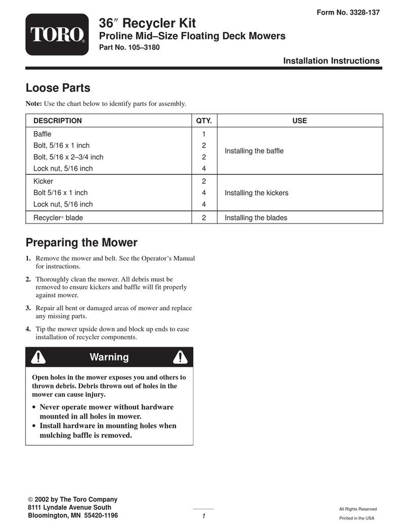
Toro 02856 User manual

FormNo.3443-338RevA
FlashingLEDBeaconKit
LT2240CompactTriple4-WheelDriveTurfMower,LT3340Triple
ReelMower,orLT-F3000TripleFlailMower
ModelNo.02856—SerialNo.400000000andUp
InstallationInstructions
PreparingtoInstallthe
FlashingBeaconKit
PreparingtheMachine
1.Parkthemachineonalevelsurface.
2.Lowerthecuttingunits.
3.Engagetheparkingbrake.
4.Shutofftheengineandremovethekey.
5.Waitforallmovingpartstostop.
6.Allowtheenginetocoolcompletely.
RemovingtheStorage
Compartment
Models31657and31659
1.Attheleftsideoftheoperator’splatform,open
thedoorofthestoragecompartment(Figure1).
g328513
Figure1
1.Washer3.Storagecompartment
2.Knob
2.Removethe3knobsand3washersthatsecure
thestoragecompartmenttothemachine,and
removethecompartment(Figure1).
OpeningtheHood
Model31654
1.Insertthehoodkeyintothelockforthehoodand
rotatethelock90°counterclockwise(Figure2).
2.Releasethehoodlatchbypressingthebutton
onthehoodlatch(Figure2).
©2020—TheToro®Company
8111LyndaleAvenueSouth
Bloomington,MN55420
Registeratwww.T oro.com.OriginalInstructions(EN)
PrintedintheUK
AllRightsReserved*3443-338*

g189331
Figure2
3.Carefullyrotatethehoodbackanddown(Figure
3).
g189330
Figure3
Models31657and31659
1.Removethe2hoodlatchesfromthelatch
catches(Figure4).
g036762
Figure4
2.Insertthehoodkeyintothelockforthehood
androtatethelock90°counterclockwise.
3.Carefullyrotatethehoodbackanddown(Figure
5).
g036763
Figure5
DisconnectingtheBattery
1.Loosentheforwardnutofthenegative
battery-cableterminal(Figure6).
g344733
Figure6
1.Nut(negative
battery-cableterminal)
2.Negativebatterypost
2.Liftthenegativebatterycablefromthebattery
post(Figure4).
Note:Positionthenegative-batterycablewhere
itcannotcontactthenegativebatterypost.
2

RemovingtheBulkheadPanel
1.Ifaroadlightisinstalledonthemachine,
disconnectthe2pinconnectorfromthenumber
plate.
2.Removethe4bolts(6x25mm),4lockwashers
(6mm),and4atwashers(6mm)thatsecure
thebulkheadpaneltothechassisofthemachine
(Figure7).
g037067
Figure7
1.Bulkheadpanel3.Lockwasher
2.Flatwasher4.Bolt
3.Movethepanelupandforward,andremoveit
fromthemachine(Figure7).
InstallingtheKit
InstallingtheBrackets
ForMachinesWithoutCabsOnly
Note:Youcaninstallthebeaconlightoneitherside
oftheROPSframe.Ifyoudriveontheleftsideof
theroad,installthebeaconontherightsideifthe
machine.Ifyoudriveontherightsideoftheroad,
installthebeaconontheleftsideofthemachine.
1.EnsurethattheROPSpivotboltsandpinsare
inplaceandtight.
2.OnthesamesideoftheROPSonwhichyou
plantoinstallthekit,removethenutandbolt
fromtheROPSanddiscardthem;refertoFigure
8.
g344020
Figure8
1.Bolt(discard)3.Locknut(discard)
2.Lanyardwasher
3.AligntheholeintheROPSbracketwiththehole
intheROPSandinstallthenewbolt(Figure9).
g344021
Figure9
1.Largebolt3.Lanyardwasher
2.ROPSbracket4.Largelocknut
4.Installthenewlargelocknutandtheexisting
lanyardwasher,andtightenthelocknut.
Note:Donotovertightenthem,asthiswill
maketheROPSdifculttofold.
5.Alignthesmallholesinthebeaconbracketwith
theupperholesintheROPSbracket(Figure
10),andsecurethebracketswith2bolts(M6x
20mm)and2locknuts(M6).
3

g345641
Figure10
1.Beaconbracket3.Locknut(M6)
2.Bolt(M6x20mm)
InstallingtheBeacononaMachine
withoutaCab
1.Installthebeaconstandtothebeaconbracket
(Figure11).
g344042
Figure11
1.Beaconstand4.Ferrite
2.Seal5.Beaconcable
3.Nut
2.Totthebeaconcable,startbyremovingthe
ttinginthetopofthebeaconstandandfeed
thebeaconcablethroughthebottomandout
throughthetop.
3.Connectthebeaconcable,ensuringthatthe
positive(yellow)wireisttedtothecentral
positiveterminalofthebeaconstandtting,and
theblackwiretotheouterterminal.Screwthe
ttingbackintothebeaconstand.
Note:Rotatethecableasyouscrewinthe
connector.Thispreventsthecablefrombeing
twisted.
4.Loosenthewingnutonthebeacon(Figure12).
g344043
Figure12
1.Wingnut
5.Assemblethebeaconontothetopofthebeacon
stand(Figure13).
4

g344044
Figure13
6.Tightenthewingnutontheclamp(Figure14).
g344045
Figure14
1.Bolt3.Lockwasher
2.Washer4.Wingnut
7.RoutethecabledownthefrontoftheROPS
frame,ensuringthatitcannotbetrappedor
chafedwhentheROPSisfoldedorraised.
8.Connectthecabletothematingconnectoron
themainwiringloomwiththeyellowandblack
wires.
•Onmodel31654,thematingconnectoris
locatednearthehorn.
•Onmodels31657and31659,themating
connectorislocatedundertheplastic
bulkheadatthebottomoftherightROPS
post.
9.Insertacabletiethrougheachofthe2holes
inthebeaconbracket(Figure15),andsecure
thecable.
g344048
Figure15
1.Holes(beaconbracket)
InstallingtheBeacononaMachine
withaCab
Note:Thewireharnessisnotrequiredforinstallation
onamachinewithacab(wiringsuppliedincab).
1.Installthebeaconstandtothebeaconbracket
(Figure16).
g344082
Figure16
1.Beaconstand4.Ferrite
2.Seal5.Beaconcable
3.Nut
2.Totthebeaconcable,startbyremovingthe
ttinginthetopofthebeaconstandandfeed
5

thebeaconcablethroughthebottomandout
throughthetop.
3.Connectthebeaconcable,ensuringthatthe
redconnectoristtedtothecentralpositive
terminalofthebeaconstandtting,andthe
brownconnectortotheouterterminal.Screw
thettingbackintothebeaconstand.
Note:Rotatethecableasyouscrewinthe
connector.Thispreventsthecablefrombeing
twisted.
4.Loosenthewingnutonthebeacon(Figure17).
g344043
Figure17
1.Wingnut
5.Assemblethebeaconontothetopofthebeacon
stand(Figure18).
g344107
Figure18
6.Tightenthewingnutontheclamp(Figure19).
g344104
Figure19
1.Bolt3.Lockwasher
2.Washer4.Wingnut
InstallingtheSwitch
1.Locate,remove,anddiscardtheblankingplug
onthemaincontrolpanel.
Note:Theblankingplugislocatedontheend
orsideofthemaincontrolpaneldependingon
themachinemodel.
2.PullouttheswitchconnectorlabeledBEACON
andplugintheswitch.
3.Presstheswitchintothecutoutuntilitclicksinto
place(Figure20andFigure21).
6

g034461
Figure20
1.Switchformodel31654
g344108
Figure21
1.Switchformodels31657and31659
CompletingtheInstallation
InstallingtheBulkheadPanel
1.Alignthe4holesinthebulkheadpanelwiththe
4clipnutsonthechassis;refertoFigure7in
RemovingtheBulkheadPanel(page3).
2.Securethebulkheadpaneltothechassisofthe
machinewiththe4bolts,4lockwashers,and4
atwashers;refertoFigure7inRemovingthe
BulkheadPanel(page3).
3.Torquetheboltsto7.7to11.6N∙m(68to103
in-lb).
4.Connectthe2pinconnectortothenumberplate
ifpreviouslydisconnected.
InstallingtheFuse
Models31657and31659
1.Removethefuse-blockcover(Figure22).
Note:Onmodels31657and31659,thefuse
blockislocatednexttothebattery.
g328464
Figure22
1.Fuseblock2.Fuse-blockcover
2.Installthefuseintheappropriatelocation;refer
tothefuseblockdecal(Figure23).
g328465
Figure23
3.Installthefuse-blockcover.
7

Model31654
1.Removethefuse-blockcover(Figure24).
Note:Onmodel31654,thefuseblockis
locatedbehindtheseatundertheenginecover.
g037069
Figure24
1.Fuse-blockcover
2.Installthefuseintheslotinthefuseblock
locatedatthe3rdpositionfromtheright(Figure
25).
g188128
Figure25
1.10Afuse2.Fuseblocksocket(3rd
positionfromtheright)
3.Installthefuseblockcover.
InstallingtheStorage
Compartment
Models31657and31659
1.Aligntheholesonthebottomofthestorage
compartmentwiththeholesinthechassis
brackets.
2.Assemblethestoragecompartmenttothe
machinewiththe3knobsand3washers(Figure
26).
g328512
Figure26
1.Washer3.Storagecompartment
2.Knob
ConnectingtheBattery
1.Assembletheterminalofthenegativebattery
cable(Figure27)ontothenegativebatterypost.
g344733
Figure27
1.Nut(negative
battery-cableterminal)
2.Negativebatterypost
2.TightentheforwardnutandT-bolt(Figure27)of
thenegativebatterycableterminal.
ApplyingtheSerialLabeland
LoweringtheHood
1.Applytheseriallabeltotherightoftherear
bulkhead,nearthemachineseriallabel.
2.Closeandsecurethehood.
3.Formodel31654only,rotatethelock90°
clockwisetotheLOCKposition.
8

Operation
UsingtheBeacon
Toturnonthebeacon,pressthebottomoftheswitch.
Toshutoffthebeacon,pressthetopoftheswitch.
Note:Theignitionswitchmustbeinposition1for
thebeacontowork.
Maintenance
ReplacingtheFuse
ReplacingtheFuseonModel
31654
1.Removethefuse-blockcover(Figure28).
g188141
g037069
Figure28
1.Fuse-blockcover
2.Removethe10Afusefromtheslotinthefuse
blocklocatedatthe3rdpositionfromtheright
(Figure29).
g188128
Figure29
1.10Afuse2.Fuseblocksocket(3rd
positionfromtheright)
3.Inserta10Afuseintotheslotofthefuseblock
locatedatthe3rdpositionfromtheright(Figure
29).
Important:Alwaysuseafuseofthesame
typeandamperageastheoneyouare
replacing;otherwise,youcoulddamagethe
electricalsystem.
Note:Ensurethatthefuseisfullyseated.
4.Installthefuse-blockcover(Figure28).
ReplacingtheFuseonModels
31657and31659
1.Removethestoragecompartment;referto
RemovingtheStorageCompartment(page1).
2.Removethefuse-blockcover(Figure30).
g328464
Figure30
1.Fuseblock2.Fuse-blockcover
3.Removetheexistingbeaconlightfuseandinsert
a10Afuseinthesameslot.
9

Notes:

Notes:

Notes:

EuropeanPrivacyNotice
TheInformationT oroCollects
ToroWarrantyCompany(Toro)respectsyourprivacy.Inordertoprocessyourwarrantyclaimandcontactyouintheeventofaproductrecall,weaskyou
tosharecertainpersonalinformationwithus,eitherdirectlyorthroughyourlocalT orocompanyordealer.
TheT orowarrantysystemishostedonserverslocatedwithintheUnitedStateswhereprivacylawmaynotprovidethesameprotectionasapplies
inyourcountry.
BYSHARINGYOURPERSONALINFORMATIONWITHUS,YOUARECONSENTINGTOTHEPROCESSINGOFYOURPERSONALINFORMATION
ASDESCRIBEDINTHISPRIVACYNOTICE.
TheWayT oroUsesInformation
Toromayuseyourpersonalinformationtoprocesswarrantyclaims,tocontactyouintheeventofaproductrecallandforanyotherpurposewhichwetell
youabout.T oromayshareyourinformationwithT oro'safliates,dealersorotherbusinesspartnersinconnectionwithanyoftheseactivities.Wewillnot
sellyourpersonalinformationtoanyothercompany.Wereservetherighttodisclosepersonalinformationinordertocomplywithapplicablelawsand
withrequestsbytheappropriateauthorities,tooperateoursystemsproperlyorforourownprotectionorthatofotherusers.
RetentionofyourPersonalInformation
Wewillkeepyourpersonalinformationaslongasweneeditforthepurposesforwhichitwasoriginallycollectedorforotherlegitimatepurposes
(suchasregulatorycompliance),orasrequiredbyapplicablelaw.
Toro'sCommitmenttoSecurityofYourPersonalInformation
Wetakereasonableprecautionsinordertoprotectthesecurityofyourpersonalinformation.Wealsotakestepstomaintaintheaccuracyandcurrent
statusofpersonalinformation.
AccessandCorrectionofyourPersonalInformation
Ifyouwouldliketorevieworcorrectyourpersonalinformation,pleasecontactusbyemailat[email protected].
AustralianConsumerLaw
AustraliancustomerswillnddetailsrelatingtotheAustralianConsumerLaweitherinsidetheboxoratyourlocalToroDealer.
374-0282RevC

TheToroWarranty
ALimitedWarranty
ConditionsandProductsCovered
TheT oro®Companyanditsafliate,T oroWarrantyCompany,pursuant
toanagreementbetweenthem,jointlywarrantyourT oroCommercial
product(“Product”)tobefreefromdefectsinmaterialsorworkmanship
fortwoyearsor1500operationalhours*,whicheveroccursrst.This
warrantyisapplicabletoallproductswiththeexceptionofAerators
(refertoseparatewarrantystatementsfortheseproducts).Wherea
warrantableconditionexists,wewillrepairtheProductatnocosttoyou
includingdiagnostics,labor,parts,andtransportation.Thiswarranty
beginsonthedatetheProductisdeliveredtotheoriginalretailpurchaser.
*Productequippedwithanhourmeter.
InstructionsforObtainingWarrantyService
YouareresponsiblefornotifyingtheCommercialProductsDistributoror
AuthorizedCommercialProductsDealerfromwhomyoupurchasedthe
Productassoonasyoubelieveawarrantableconditionexists.Ifyouneed
helplocatingaCommercialProductsDistributororAuthorizedDealer,or
ifyouhavequestionsregardingyourwarrantyrightsorresponsibilities,
youmaycontactusat:
CommercialProductsServiceDepartment
ToroWarrantyCompany
8111LyndaleAvenueSouth
Bloomington,MN55420-1196
E-mail:[email protected]
OwnerResponsibilities
AstheProductowner,youareresponsibleforrequiredmaintenanceand
adjustmentsstatedinyourOperator’sManual.Failuretoperformrequired
maintenanceandadjustmentscanbegroundsfordisallowingawarranty
claim.
ItemsandConditionsNotCovered
Notallproductfailuresormalfunctionsthatoccurduringthewarranty
periodaredefectsinmaterialsorworkmanship.Thiswarrantydoesnot
coverthefollowing:
•Productfailureswhichresultfromtheuseofnon-T ororeplacement
parts,orfrominstallationanduseofadd-on,ormodiednon-T oro
brandedaccessoriesandproducts.Aseparatewarrantymaybe
providedbythemanufactureroftheseitems.
•Productfailureswhichresultfromfailuretoperformrecommended
maintenanceand/oradjustments.Failuretoproperlymaintainyour
ToroproductpertheRecommendedMaintenancelistedinthe
Operator’sManualcanresultinclaimsforwarrantybeingdenied.
•ProductfailureswhichresultfromoperatingtheProductinanabusive,
negligentorrecklessmanner.
•Partssubjecttoconsumptionthroughuseunlessfoundtobedefective.
Examplesofpartswhichareconsumed,orusedup,duringnormal
Productoperationinclude,butarenotlimitedto,brakespadsand
linings,clutchlinings,blades,reels,bedknives,tines,sparkplugs,
castorwheels,tires,lters,belts,andcertainsprayercomponents
suchasdiaphragms,nozzles,andcheckvalves,etc.
•Failurescausedbyoutsideinuence.Itemsconsideredtobeoutside
inuenceinclude,butarenotlimitedto,weather,storagepractices,
contamination,useofunapprovedcoolants,lubricants,additives,
fertilizers,water,orchemicals,etc.
•Normalnoise,vibration,wearandtear,anddeterioration.
•Normal“wearandtear”includes,butisnotlimitedto,damagetoseats
duetowearorabrasion,wornpaintedsurfaces,scratcheddecalsor
windows,etc.
Parts
Partsscheduledforreplacementasrequiredmaintenancearewarranted
fortheperiodoftimeuptothescheduledreplacementtimeforthatpart.
Partsreplacedunderthiswarrantyarecoveredforthedurationofthe
originalproductwarrantyandbecomethepropertyofT oro.T orowillmake
thenaldecisionwhethertorepairanyexistingpartorassemblyorreplace
it.T oromayuseremanufacturedpartsforwarrantyrepairs.
NoteRegardingDeepCycleBatteryWarranty:
Deepcyclebatterieshaveaspeciedtotalnumberofkilowatt-hoursthey
candeliverduringtheirlifetime.Operating,recharging,andmaintenance
techniquescanextendorreducetotalbatterylife.Asthebatteriesin
thisproductareconsumed,theamountofusefulworkbetweencharging
intervalswillslowlydecreaseuntilthebatteryiscompletelywornout.
Replacementofwornoutbatteries,duetonormalconsumption,isthe
responsibilityoftheproductowner.Batteryreplacementmayberequired
duringthenormalproductwarrantyperiodatowner’sexpense.
MaintenanceisatOwner’sExpense
Enginetune-up,lubricationcleaningandpolishing,replacementofItems
andConditionsNotCoveredlters,coolant,andcompletingRecommended
MaintenancearesomeofthenormalservicesT oroproductsrequirethat
areattheowner’sexpense.
GeneralConditions
RepairbyanAuthorizedToroDistributororDealerisyoursoleremedy
underthiswarranty.
NeitherTheToroCompanynorToroWarrantyCompanyisliablefor
indirect,incidentalorconsequentialdamagesinconnectionwiththe
useoftheToroProductscoveredbythiswarranty,includingany
costorexpenseofprovidingsubstituteequipmentorserviceduring
reasonableperiodsofmalfunctionornon-usependingcompletion
ofrepairsunderthiswarranty.ExceptfortheEmissionswarranty
referencedbelow,ifapplicable,thereisnootherexpresswarranty.
Allimpliedwarrantiesofmerchantabilityandtnessforusearelimitedtothe
durationofthisexpresswarranty.Somestatesdonotallowexclusionsof
incidentalorconsequentialdamages,orlimitationsonhowlonganimplied
warrantylasts,sotheaboveexclusionsandlimitationsmaynotapplytoyou.
Thiswarrantygivesyouspeciclegalrights,andyoumayalsohaveother
rightswhichvaryfromstatetostate.
CountriesOtherthantheUnitedStatesorCanada
CustomersshouldcontacttheirT oroDistributor(Dealer)toobtainguaranteepoliciesforyourcountry,province,orstate.Ifforanyreasonyouare
dissatisedwithyourDistributor'sserviceorhavedifcultyobtainingguaranteeinformation,contacttheT oroimporter.Ifallotherremediesfail,you
maycontactusatT oroWarrantyCompany.
374-0277RevB

Table of contents
Other Toro Lawn Mower Accessories manuals
Toro
Toro 136-8550 User manual

Toro
Toro 79120 User manual

Toro
Toro 03611 User manual

Toro
Toro Pro Sweep 5200 User manual

Toro
Toro 161-4450 User manual

Toro
Toro 03860 User manual

Toro
Toro Greensmaster eFlex 1018 User manual

Toro
Toro 137-5470 User manual

Toro
Toro 08838 User manual

Toro
Toro Reelmaster 5010- H User manual
Popular Lawn Mower Accessories manuals by other brands

Snapper
Snapper 6-1056 Installation instructions and parts list

MTD
MTD 190-560-000 owner's guide

Pottinger
Pottinger NOVADISC 225 Operator's manual

Yard-Man
Yard-Man ZYJ-1361-A Owners operating manual and parts list

Ferris
Ferris 5049751 installation instructions

Cub Cadet
Cub Cadet 759-04080 installation instructions