Toro 132-9543 User manual

FormNo.3397-700RevA
ConsoleKit
Greensmaster®3320or3420SeriesTriFlex®TractionUnit
ModelNo.132-9543
InstallationInstructions
Safety
SafetyandInstructionalDecals
Safetydecalsandinstructionsareeasilyvisibletotheoperatorandarelocatednearanyareaofpotential
danger.Replaceanydecalthatisdamagedorlost.
132-9548
1.Enginespeed(high)7.Tractionunit(neutral)
2.Enginespeed(low)8.Reel(transport)
3.Lowerandengagethereels9.Reel(mow)
4.Raiseanddisengagethereels10.Reel(backlaping)
5.Tractionunit(transport)11.Moveforward
6.Tractionunit(mow)
©2016—TheToro®Company
8111LyndaleAvenueSouth
Bloomington,MN55420
Registeratwww.Toro.com.OriginalInstructions(EN)
PrintedintheUSA
AllRightsReserved*3397-700*A

132-9550
1.Choke3.Engine(run)
2.Engine(start)4.Engine(stop)
Installation
LooseParts
Usethechartbelowtoverifythatallpartshavebeenshipped.
DescriptionQty.Use
Nopartsrequired–Preparethemachine.
Nopartsrequired–Removetheconsole.
ConsoleAssembly1
Speednut4
Threadclip(1/4inch)2
Choke-leverassembly1
Function-controlbracket1
Bolt(#10x1/2inch)4
Bolt(1/4x5/8inch)2
Neutral-lockcable1
Locknut(#10)2
Upperdecal1
Lowerdecal1
Slotcover1
Bolt(#10x3/8inch)1
Slottedbolt(#10x3/8inch)2
Installthekit.
Nopartsrequired–Completetheinstall.
2

PreparingtheMachine
1.Movethemachinetoalevelworkspace.
2.Shutofftheengine,settheparkingbrake,andremove
thekeyfromtheignitionswitch.
3.Disconnectthebattery;RefertotheOperator’sManual.
RemovingtheConsole
RemovingtheConsoleCover
Note:Setasidealloftheitemsthatyouremovefromthis
procedure.
Removethe8boltsthatsecuretheconsolecovertothe
consoleassembly().
Figure1
1.Bolt2.Cover
DisconnecttheWireHarness
Disconnectthewireharnessfromthecontrols,switches,and
indicatorsmountedontheconsoleassembly(Figure2).
Figure2
1.Control,indicator,or
switch
2.Connector
Note:Itisnotnecessarytodisconnecttheproximitysensors
oraudioalarm.
RemovingtheThrottleAssembly
Note:Setasidealloftheitemsthatyouremovefromthis
procedure.
1.Removetheknobfromthethrottle-levershaft.
2.Removeanddiscardthe2boltsandlocknutsthat
securethethrottleassemblytotheconsoleassembly
(Figure3).
Figure3
1.Bolt3.Throttleassembly
2.Locknut
Note:Donotdisconnectthethrottlecablefromthe
engine.
3

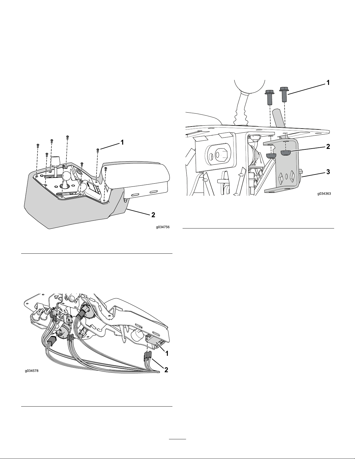
RemovingtheMow-ControlAssembly
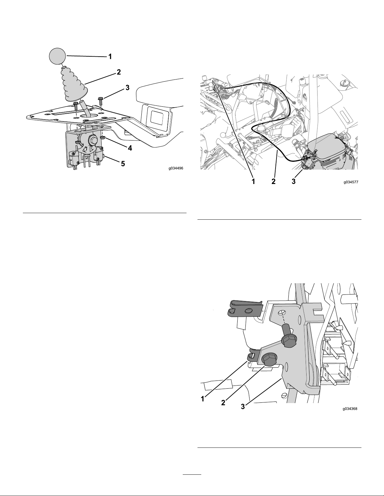
1.Removeandsetasidetheknobfromthemow-control
shaft(Figure4).
Figure4
1.Knob4.Nut
2.Dustboot5.Mow-controlassembly
3.Bolt
2.Removeandsetasidethedustbootfromthe
mow-controlshaft(Figure4).
3.Removeandsetasidethe2boltsandnutssecuring
mow-controlassemblytotheconsoleassembly(Figure
4).
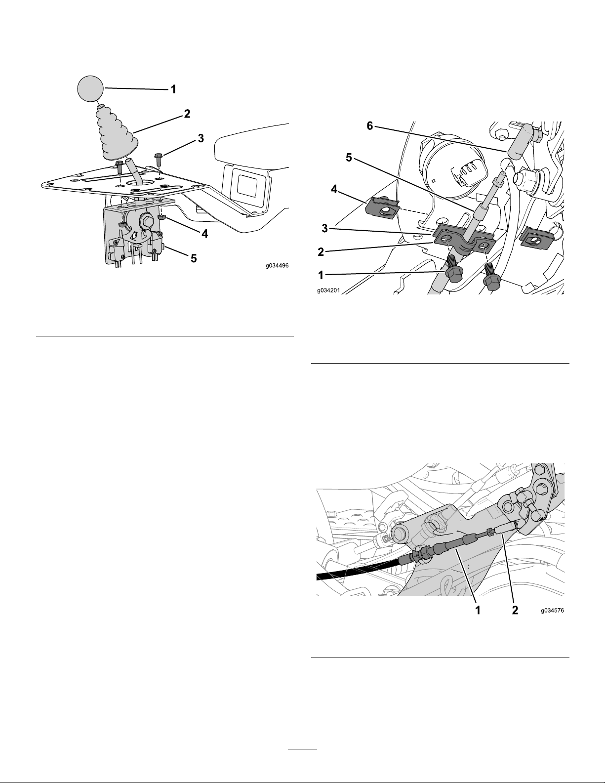
RemovingtheFunction-Control
Assembly
Note:Setasidealloftheitemsthatyouremoveinthe
followingprocedureunlessotherwiseinstructed.
1.Removethe2boltsandnutclipsecuringcableclamp
andshimtotheconsoleassembly(Figure5).
Figure5
1.Bolt4.Nutclip
2.Cableclamp5.Neutral-lockcable
3.Shim6.Cableconnector
2.Setasidethecableclampanddiscardtheshim(Figure
5).
3.Disconnecttheneutral-lockcablefromthecable
connector(Figure5).
4.Disconnecttheneutral-lockcablefromtheball-joint
connectoronthetraction-rodassembly(Figure6).
Figure6
1.Neutral-lockcable2.Ball-jointconnector
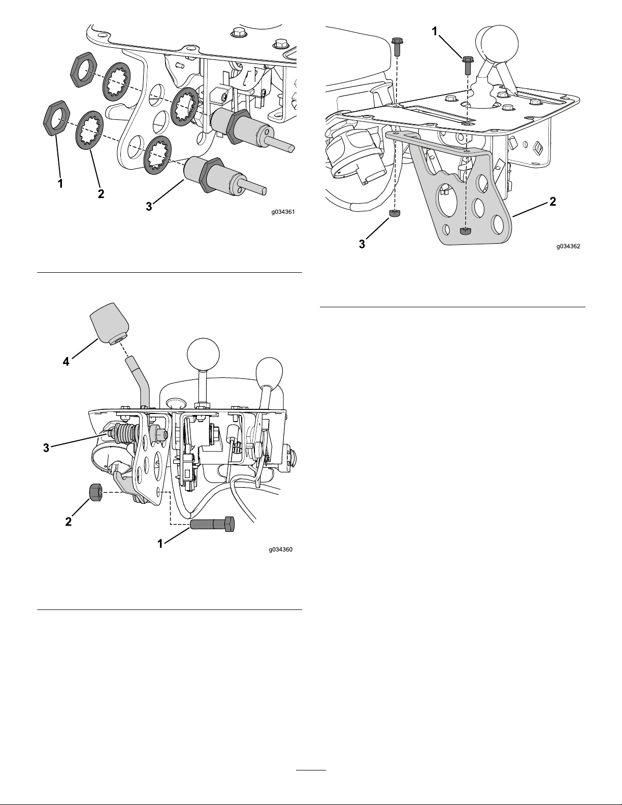
5.Removethenutssecuringtheproximitysensorstothe
function-leverbracket(Figure7).
4

Figure7
1.Retainingnut3.Proximitysensor
2.Washer
6.Removetheknobfromthefunctionlever(Figure8).
Figure8
1.Bolt3.Function-leverassembly
2.Nut4.Knob
7.Removetheboltandnutthatsecuresthefunction-lever
assemblytothefunction-leverbracket(Figure8).
8.Removeanddiscardthe2boltsandnutsthatsecure
thefunction-controlbrackettotheconsoleassembly
(Figure9).
Figure9
1.Bolt3.Nut
2.Function-controlassembly
DisconnectingtheChokeCable
1.Disconnectthecablefromthechokecontrolonthe
engine.
2.Removethecablefromthetractionunit.
3.Leavethecableconnectedtoconsoleassembly,itwill
beremovedwiththeconsoleassembly.
Note:Replacebutdonotcompletelytightenthecableties
whenyouremovethechokecable.Thiswillalsohelpyou
whenroutingthenewcable.
5

RemovingtheSwitchesandIndicators
Note:Setasidealloftheitemsthatyouremovefromthis
procedure.
1.Removetheretainingringtoremovethedisplayfrom
theconsoleassembly(Figure10).
Figure10
1.Display2.Retainingring
2.Removetheknurled-retainingringonthealarmand
removeitfromtheconsoleassembly(Figure11).
Figure11
1.Audioalarm2.Retainingring
3.Removetheretainerthatsecuresthehourmeterfrom
theconsoleassembly,ifequipped(Figure12).
Figure12
CutawayView
1.Hourmeter3.Cutaway
2.Retainer
4.Removetheretainingnutontheignitionswitchto
removeitfromtheconsoleassembly(Figure13).
Figure13
1.Retainingnut2.Startswitch
6

RemovingtheConsoleAssembly
Setasidealloftheitemsthatyouremovefromthisprocedure.
1.Removethe2carriageboltsandangenutsthatsecure
theconsoleassemblytotheconsolebracket(Figure14).
Figure14
1.Consoleassembly3.Armrest
2.Flangenut4.Carriagebolt
Note:Dieselpoweredmachineshaveaspacer
betweentheconsoleassemblyandbracket.
2.Remove2angenutssecuringthearmrestfromthe
consoleassembly(Figure14).
InstallingtheKit
InstallingtheConsoleAssembly
1.Installtheupperandlowerdecaltotheconsole
assembly(Figure15).
Figure15
1.Consoleassembly3.Upperdecal
2.Lowerdecal
2.Usethe2carriageboltsandangenutsthatyou
removedearliertosecuretheconsolebracket(Figure
16).
Note:Installthespaceronmachinesthatarediesel
powered.
Figure16
1.Consoleassembly4.Spacer(dieselonly)
2.Flangenut5.Carriagebolt
3.Armrest
3.Usethe2angenutsyouremovedearliertosecurethe
armresttotheconsoleassembly(Figure16).
7

InstallingtheMow-ControlAssembly
1.Usethe2bolts(#10x1/2inch)andlocknutstosecure
thejoystickassemblytotheconsole(Figure17).
Figure17
1.Knob4.Nut
2.Dustboot5.Mow-controlassembly
3.Bolt
2.Installthedustbootoverthejoystickshaft.
3.Installtheknobtothejoystickshaft.
InstallingtheChokeAssembly
GasEngineOnly
1.Followtheoriginalcableroutingtoroutethenew
chokecableandsecureittothemachinewithcable
ties(Figure18).
Figure18
1.Choke-leverassembly3.Chokecontrol
2.Chokecable
2.Connectthecabletothechokecontrolontheengine
(Figure18).
3.Installthespeednutsontothemountontheconsole
assembly(Figure19).
4.Usethe2bolts(#10x1/2inch)tosecurethe
choke-leverassemblytotheconsole(Figure19).
Figure19
1.Speednut(installed)3.Choke-leverassembly
2.Bolts(#10x1/2inch)
8

InstallingtheSlotCover
DieselEngineOnly
Usethebolt(#10x3/8inch)tosecuretheslotcovertothe
console(Figure20).
Figure20
1.Bolt(#10x3/8inch)2.Slotcover
InstallingtheFunction-Control
Assembly
1.Usethebolt(#10x1/2inch)andlocknuttosecurethe
function-leverbrackettotheconsole(Figure21).
Figure21
1.Bolt(#10x1/2inch)3.Function-leverbracket
2.Locknut
2.Usethelocknut,atwasher,spacertube,andboltthat
youremovedearliertosecurethehandleassemblyto
thebracket(Figure22).
Figure22
1.Locknut(10mm)4.Splitbushing
2.Flatwasher5.Leverassembly
3.Spacertube6.Bolt(10mmx40mm)
3.Usethenutsandlockwashersthatyouremovedearlier
tosecuretheproximitysensorstothefunction-lever
bracket(Figure23).
Figure23
1.Nut3.Proximitysensor
2.Lockwasher
4.Installtheknobtothefunction-levershaft.
9

InstallingtheNeutral-LockCable
1.Removetheoriginalcableandroutethenewcablein
itsplace.
2.Connecttheneutral-lockcabletothepedalshifter
(Figure24).
Figure24
1.Neutral-lockcable2.Ball-jointconnector
3.Connecttheneutral-lockcabletothecableconnector
(Figure25).
Figure25
1.Bolt(1/4x5/8inch)4.Cable
2.Cableclamp5.Cableconnector
3.Retainernut
4.Installtheretainernutontotheconsoleassembly
(Figure25).
5.Usethe2bolts(1/4x5/8inch)tosecurethecablewith
thecableclamptotheconsoleassembly(Figure25).
6.Securethecabletothemachinewithcableties.
InstallingtheSwitchesandIndicators
1.Presshourmeterintothecutoutuntilitissecurewith
theretainer(Figure26).
Figure26
CutawayView
1.Hourmeter3.Cutaway
2.Retainer
2.Usetheretainingringtosecuretheaudioalarmtothe
consoleassembly(Figure27).
Figure27
1.Audioalarm2.Retainingring
3.Usetheretainingringtosecurethedisplaytothe
consoleassemble(Figure28).
10

Figure28
1.Display2.Retainingring
4.Usetheretainingnutyouremovedearliertosecurethe
ignitionswitchtotheconsoleassembly(Figure29).
Figure29
1.Retainingnut2.Startswitch
5.Connectthewireharnesstotheappropriate
connections(Figure30).
Figure30
1.Control,indicator,or
switch
2.Connector
CompletingtheInstall
1.Usethe8boltsthatyouremovedearliertosecurethe
consolecovertotheconsoleassembly(Figure31).
Figure31
1.Bolt(10x1/2inch)2.Consolecover
2.Connectthebattery:RefertotheOperator’sManual.
3.Verifythefunctionofthecontrolsandadjustif
necessary.
11

TheToroWarranty
ATwo-YearLimitedWarranty
ConditionsandProductsCovered
TheT oroCompanyanditsafliate,ToroWarrantyCompany,pursuant
toanagreementbetweenthem,jointlywarrantyourToroCommercial
product(“Product”)tobefreefromdefectsinmaterialsorworkmanship
fortwoyearsor1500operationalhours*,whicheveroccursrst.This
warrantyisapplicabletoallproductswiththeexceptionofAerators
(refertoseparatewarrantystatementsfortheseproducts).Wherea
warrantableconditionexists,wewillrepairtheProductatnocosttoyou
includingdiagnostics,labor,parts,andtransportation.Thiswarranty
beginsonthedatetheProductisdeliveredtotheoriginalretailpurchaser.
*Productequippedwithanhourmeter.
InstructionsforObtainingWarrantyService
YouareresponsiblefornotifyingtheCommercialProductsDistributoror
AuthorizedCommercialProductsDealerfromwhomyoupurchasedthe
Productassoonasyoubelieveawarrantableconditionexists.Ifyouneed
helplocatingaCommercialProductsDistributororAuthorizedDealer,or
ifyouhavequestionsregardingyourwarrantyrightsorresponsibilities,
youmaycontactusat:
ToroCommercialProductsServiceDepartment
ToroWarrantyCompany
8111LyndaleAvenueSouth
Bloomington,MN55420-1196
952–888–8801or800–952–2740
E-mail:[email protected]
OwnerResponsibilities
AstheProductowner,youareresponsibleforrequiredmaintenanceand
adjustmentsstatedinyourOperator'sManual.Failuretoperformrequired
maintenanceandadjustmentscanbegroundsfordisallowingawarranty
claim.
ItemsandConditionsNotCovered
Notallproductfailuresormalfunctionsthatoccurduringthewarranty
periodaredefectsinmaterialsorworkmanship.Thiswarrantydoesnot
coverthefollowing:
•Productfailureswhichresultfromtheuseofnon-T ororeplacement
parts,orfrominstallationanduseofadd-on,ormodiednon-T oro
brandedaccessoriesandproducts.Aseparatewarrantymaybe
providedbythemanufactureroftheseitems.
•Productfailureswhichresultfromfailuretoperformrecommended
maintenanceand/oradjustments.Failuretoproperlymaintainyour
ToroproductpertheRecommendedMaintenancelistedinthe
Operator’sManualcanresultinclaimsforwarrantybeingdenied.
•ProductfailureswhichresultfromoperatingtheProductinanabusive,
negligent,orrecklessmanner.
•Partssubjecttoconsumptionthroughuseunlessfoundtobedefective.
Examplesofpartswhichareconsumed,orusedup,duringnormal
Productoperationinclude,butarenotlimitedto,brakepadsand
linings,clutchlinings,blades,reels,rollersandbearings(sealedor
greasable),bedknives,sparkplugs,castorwheelsandbearings,tires,
lters,belts,andcertainsprayercomponentssuchasdiaphragms,
nozzles,andcheckvalves,etc.
•Failurescausedbyoutsideinuence.Conditionsconsideredtobe
outsideinuenceinclude,butarenotlimitedto,weather,storage
practices,contamination,useofunapprovedfuels,coolants,lubricants,
additives,fertilizers,water,orchemicals,etc.
•Failureorperformanceissuesduetotheuseoffuels(e.g.gasoline,
diesel,orbiodiesel)thatdonotconformtotheirrespectiveindustry
standards.
•Normalnoise,vibration,wearandtear,anddeterioration.
•Normal“wearandtear”includes,butisnotlimitedto,damagetoseats
duetowearorabrasion,wornpaintedsurfaces,scratcheddecalsor
windows,etc.
Parts
Partsscheduledforreplacementasrequiredmaintenancearewarranted
fortheperiodoftimeuptothescheduledreplacementtimeforthatpart.
Partsreplacedunderthiswarrantyarecoveredforthedurationofthe
originalproductwarrantyandbecomethepropertyofT oro.T orowillmake
thenaldecisionwhethertorepairanyexistingpartorassemblyorreplace
it.T oromayuseremanufacturedpartsforwarrantyrepairs.
DeepCycleandLithium-IonBatteryWarranty:
DeepcycleandLithium-Ionbatterieshaveaspeciedtotalnumberof
kilowatt-hourstheycandeliverduringtheirlifetime.Operating,recharging,
andmaintenancetechniquescanextendorreducetotalbatterylife.Asthe
batteriesinthisproductareconsumed,theamountofusefulworkbetween
chargingintervalswillslowlydecreaseuntilthebatteryiscompletelyworn
out.Replacementofwornoutbatteries,duetonormalconsumption,
istheresponsibilityoftheproductowner.Batteryreplacementmaybe
requiredduringthenormalproductwarrantyperiodatowner’sexpense.
Note:(Lithium-Ionbatteryonly):ALithium-Ionbatteryhasapartonly
proratedwarrantybeginningyear3throughyear5basedonthetime
inserviceandkilowatthoursused.RefertotheOperator'sManualfor
additionalinformation.
MaintenanceisatOwner’sExpense
Enginetune-up,lubrication,cleaningandpolishing,replacementoflters,
coolant,andcompletingrecommendedmaintenancearesomeofthe
normalservicesT oroproductsrequirethatareattheowner’sexpense.
GeneralConditions
RepairbyanAuthorizedT oroDistributororDealerisyoursoleremedy
underthiswarranty.
NeitherTheToroCompanynorToroWarrantyCompanyisliablefor
indirect,incidentalorconsequentialdamagesinconnectionwiththe
useoftheToroProductscoveredbythiswarranty,includingany
costorexpenseofprovidingsubstituteequipmentorserviceduring
reasonableperiodsofmalfunctionornon-usependingcompletion
ofrepairsunderthiswarranty.ExceptfortheEmissionswarranty
referencedbelow,ifapplicable,thereisnootherexpresswarranty.All
impliedwarrantiesofmerchantabilityandtnessforusearelimitedto
thedurationofthisexpresswarranty.
Somestatesdonotallowexclusionsofincidentalorconsequential
damages,orlimitationsonhowlonganimpliedwarrantylasts,sotheabove
exclusionsandlimitationsmaynotapplytoyou.Thiswarrantygivesyou
speciclegalrights,andyoumayalsohaveotherrightswhichvaryfrom
statetostate.
Noteregardingenginewarranty:
TheEmissionsControlSystemonyourProductmaybecoveredby
aseparatewarrantymeetingrequirementsestablishedbytheU.S.
EnvironmentalProtectionAgency(EPA)and/ortheCaliforniaAirResources
Board(CARB).Thehourlimitationssetforthabovedonotapplytothe
EmissionsControlSystemWarranty.RefertotheEngineEmissionControl
WarrantyStatementsuppliedwithyourproductorcontainedintheengine
manufacturer’sdocumentationfordetails
CountriesOtherthantheUnitedStatesorCanada
CustomerswhohavepurchasedToroproductsexportedfromtheUnitedStatesorCanadashouldcontacttheirT oroDistributor(Dealer)toobtain
guaranteepoliciesforyourcountry,province,orstate.IfforanyreasonyouaredissatisedwithyourDistributor'sserviceorhavedifcultyobtaining
guaranteeinformation,contacttheToroimporter.374-0253RevD
Table of contents
Other Toro Lawn Mower Accessories manuals

Toro
Toro 137-5001 User manual

Toro
Toro 03227 User manual

Toro
Toro Flex-Force Power System 51810T User manual

Toro
Toro Groundsmaster 5900 Series User manual

Toro
Toro 03860 User manual

Toro
Toro 78514 User manual

Toro
Toro 04722 User manual

Toro
Toro 112-5803 User manual

Toro
Toro SUPER RECYCLER 59193 User manual

Toro
Toro 23163 User manual
Popular Lawn Mower Accessories manuals by other brands

Worksaver
Worksaver PLR-48, PLR-60, PLR-72, PBX-42 Operator's manual

Snapper
Snapper 1690170 installation instructions

Snapper
Snapper Simplicity RZT Riding Mowers owner's manual

Peco
Peco Pro Series Operator's manual

Simplicity
Simplicity 2800 GT Series, 1800 GT Series installation instructions

Iseki
Iseki SSM48 Operation manual