Toro 30460 User manual

FormNo.3392-999RevA
GrassCollectionSystem
Groundsmaster®7200Serieswith
60-inchMower
(ForMachineswithKubotaEnginesOnly)
ModelNo.30460—SerialNo.315000001andUp
Registeratwww.Toro.com.
OriginalInstructions(EN)*3392-999*A

ThisproductcomplieswithallrelevantEuropeandirectives.
Fordetails,pleaseseetheDeclarationofIncorporation(DOI)
atthebackofthispublication.
WARNING
CALIFORNIA
Proposition65Warning
Thisproductcontainsachemicalorchemicals
knowntotheStateofCaliforniatocausecancer,
birthdefects,orreproductiveharm.
Introduction
Important:Thiskitcanonlybeusedonmachineswith
aKubotaengine.Thisincludesthefollowingmodels:
30495,30473,30487,and30381.Thekitwillalsoton
oldermodels30467,30468,and30468N.
Readthisinformationcarefullytolearnhowtooperateand
maintainyourproductproperlyandtoavoidinjuryand
productdamage.Youareresponsibleforoperatingthe
productproperlyandsafely.
YoumaycontactTorodirectlyatwww.Toro.comforproduct
andaccessoryinformation,helpndingadealer,ortoregister
yourproduct.
YoumaycontactTorodirectlyatwww.Toro.comforproduct
safetyandoperationtrainingmaterials,accessoryinformation,
helpndingadealer,ortoregisteryourproduct.
Wheneveryouneedservice,genuineToroparts,oradditional
information,contactanAuthorizedServiceDealerorToro
CustomerServiceandhavethemodelandserialnumbersof
yourproductready.Figure1identiesthelocationofthe
modelandserialnumbersontheproduct.Writethenumbers
inthespaceprovided.
Figure1
1.Collectionsystemmodelandserialnumberlocation
ModelNo.
SerialNo.
Thismanualidentiespotentialhazardsandhassafety
messagesidentiedbythesafetyalertsymbol(Figure2),
whichsignalsahazardthatmaycauseseriousinjuryordeath
ifyoudonotfollowtherecommendedprecautions.
Figure2
1.Safetyalertsymbol
Thismanualuses2wordstohighlightinformation.
Importantcallsattentiontospecialmechanicalinformation
andNoteemphasizesgeneralinformationworthyofspecial
attention.
©2014—TheToro®Company
8111LyndaleAvenueSouth
Bloomington,MN554202
Contactusatwww.Toro.com.
PrintedintheUSA.
AllRightsReserved

Contents
Safety...........................................................................3
SafetyandInstructionalDecals.................................4
Setup............................................................................5
1PreparingtheMower.............................................6
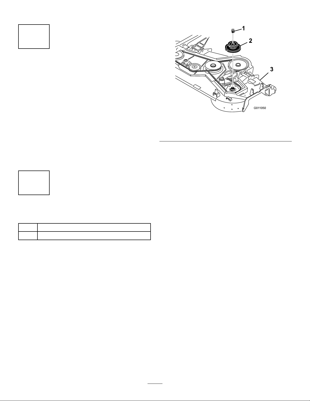
2InstallingthePulleyAssembly.................................6
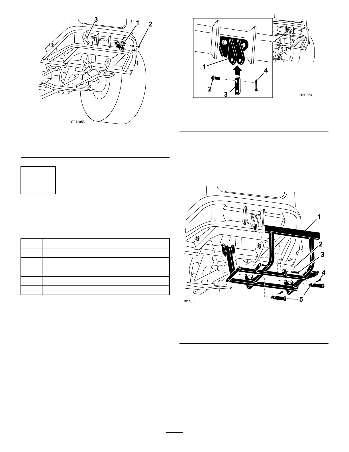
3RemovingtheExistingAnti-ScalpRollerand
Bracket...............................................................7
4InstallingtheBlowerPivotfora60inch
Bagger................................................................7
5InstallingtheLinkMountingBracket.......................8
6InstallingtheBaggerMountingBracket....................9
7InstallingtheHandleAssembly...............................9
8InstallingtheBaggerAssembly..............................10
9RoutingtheBlowerBeltintotheBlower
Assembly...........................................................12
10InstallingtheBlowerAssembly.............................12
11InstallingtheDischargeTubes.............................13
12InstallingtheBeltCoverandBolt..........................16
13InstallingtheWeightKit......................................17
14CheckingtheTirePressure..................................17
Operation....................................................................18
PositioningtheFlowBafe......................................18
EmptyingtheBagger..............................................18
ClearingObstructionsfromtheCollection
System..............................................................19
RemovingtheBagger..............................................19
OpeningtheMachineHood.....................................19
TransportingMachines............................................20
OperatingTips......................................................20
Maintenance.................................................................22
RecommendedMaintenanceSchedule(s)......................22
CleaningtheBaggerScreen......................................22
CleaningtheCollectionSystem.................................22
InspectingtheBlowerBelt.......................................22
ReplacingtheBlowerBelt........................................22
CheckingandAdjustingtheBlowerLatch..................23
GreasingtheIdlerArmandHandlePivot...................23
InspectingtheCollectionSystem..............................24
AdjustingtheDoorClosing.....................................24
AdjustingtheDoorOpening....................................25
AdjustingtheLatches..............................................25
InspectingtheMowerBlades...................................25
InstallingtheMowerBlades.....................................26
InstallingtheGrassDeector...................................26
Storage........................................................................27
Troubleshooting...........................................................28
Safety
ThefollowinglistcontainssafetyinformationspecictoToro
productsandothersafetyinformationyoumustknow.
•Becomefamiliarwiththesafeoperationoftheequipment,
withtheoperatorcontrols,andsafetysigns.
•Useextracarewithgrasscatchersorotherattachments.
Thesecanchangetheoperatingcharacteristicsandthe
stabilityofthemachine.
•Followthemanufacturer'srecommendationsforadding
orremovingwheelweightsorcounterweightstoimprove
stability.
•Donotuseagrasscatcheronsteepslopes.Aheavy
grasscatchercouldcauselossofcontroloroverturnthe
machine.
•Slowdownanduseextracareonhillsides.Besureto
travelsidetosideandnotupanddownonhillsides.Turf
conditionscanaffectthemachine'sstability.Useextreme
cautionwhileoperatingneardrop-offs.
•Keepallmovementonslopesslowandgradual.Donot
makesuddenchangesinspeed,directionsorturning.
•Thegrasscatchercanobstructtheviewtotherear.Use
extracarewhenoperatinginreverse.
•Usecarewhenloadingorunloadingthemachineintoa
trailerortruck.Ifthemachineistobedrivenontoatruck
ortrailerwiththehopperfull,alwaysbackuptheramp.
•Neveroperatewiththedischargedeectorraised,
removedoraltered,unlessusingagrasscatcher.
•Keephandsandfeetawayfrommovingparts.Donot
makeadjustmentswiththeenginerunning.
•Stoponlevelground,disengagedrives,shutoffengine
beforeleavingtheoperator'spositionforanyreason
includingemptyingthegrasscatcheroruncloggingthe
chute.
•Ifyouremovethegrasscatcher,besuretoinstallany
dischargedeectororguardthatmighthavebeen
removedtoinstallthegrasscatcher.Donotoperatethe
mowerwithouteithertheentiregrasscatcherorthegrass
deectorinplace.
•Stoptheenginebeforeremovingthegrasscatcheror
uncloggingthechute.
•Donotleavegrassingrasscatcherforextendedperiods
oftime.
•Thetractionunitcanmakeveryquickturns.Usecaution
whenturningandnotdamagethegrasscollector.
•Grasscatchercomponentsaresubjecttowear,damage
anddeterioration,whichcouldexposemovingpartsor
allowobjectstobethrown.Frequentlycheckcomponents
andreplacewithmanufacturer'srecommendedparts,
whennecessary.
3

SafetyandInstructionalDecals
Safetydecalsandinstructionsareeasilyvisibletotheoperatorandarelocatednearanyareaofpotential
danger.Replaceanydecalthatisdamagedorlost.
98-5954
106-3339
109-5890
4

Setup
LooseParts
Usethechartbelowtoverifythatallpartshavebeenshipped.
ProcedureDescriptionQty.Use
1Nopartsrequired–Preparethemower.
Doublepulleyassembly1
2Pulleynut1Installthepulleyassembly.
3Nopartsrequired–Removetheexistinganti-scalproller
andbracket.
Blowerpivot1
Metaltemplate1
Bolt(3/8x1inch)3
4Locknut(3/8inch)3
Installtheblowerpivotfora60inch
bagger.
Linkmountingbracket1
Bolt,(3/8x1inch)3
5Flangedlocknut,(3/8inch)3
Installthelinkmountingbracket
Baggermountingbracket1
Link1
Smallclevispin2
Largeclevispin2
Smallcotterpin2
6
Largecotterpin2
Installthebaggermountingbracket
Handleassembly1
Pin1
7Rollpin2
Installthehandleassembly.
Baggerassembly1
Pinandhairpincotterpinassembly2
Nut(3/8inch)2
Threadedrod1
Yoke2
8
Clevispinspring2
Installthebaggerassembly.
Blowerbelt1
9Spring1
Routetheblowerbeltintotheblower
assembly.
10Blowerassembly1Installtheblowerassembly.
Uppertube1
Middletube1
Lowertube1
Bolt,(#10x3/4inches)6
Locknut,(#10)6
11
Washer,(7/32inch)6
Installthedischargetubes.
Beltcover
Bolt(1/2x2-1/2inches)1
12Nut(1/2inch)1
Installthebeltcoverandbolt.
13Nopartsrequired–Installtheweightkit.
14Nopartsrequired–Checkthetirepressure.
5

Note:Determinetheleftandrightsidesofthemachinefromthenormaloperatingposition.
1
PreparingtheMower
NoPartsRequired
Procedure
Performthefollowingproceduretopreparethemowerfor
attachingtheblowerandnishingkit.
1.DisengagethePTO,movethemotioncontrolleversto
theneutrallockedpositionandsettheparkingbrake.
2.Stoptheengine,removethekey,andwaitforallmoving
partstostopbeforeleavingtheoperatingposition.
3.Repairallbentordamagedareasofmowerdeckand
replaceanymissingparts.
4.Cleanthemowerofanydebrisonthedeckorrearpart
ofthemowertoeaseinstallation.
2
InstallingthePulleyAssembly
Partsneededforthisprocedure:
1Doublepulleyassembly
1Pulleynut
Procedure
1.Lowerthemowerdecktothelowestheight-of-cut
position.
2.Removetherightbeltcover.Savethiscover.
3.Removethemowerdeckbeltfromtherightpulley.
4.Placeablockundertherightbladespindleunder
themowerdeckbeforeremovingtherightmower
deckpulley(Figure3).Thiswillpreventthespindle
componentsdroppingdownwhenthepulleynutis
removed.
5.Removetheexistingpulleynutandremovethepulley
(Figure3).Savethepulleyandnutforlateruse.
6.Installthenewdoublepulleyontothespindleand
secureitwiththenewpulleynut(Figure3).Torquethe
nutto130-150ft-lb(176-203N-m).
7.Afterthenewpulleyassemblyisinposition,installthe
mowerdeckbeltontothelowerpulley.
Figure3
1.Newpulleynut3.Mowerdeck
2.Doublepulleyassembly
6

3
RemovingtheExisting
Anti-ScalpRollerandBracket
NoPartsRequired
Procedure
1.Cleantheareaaroundtheright,rearanti-scalpwheel.
2.Removetheanti-scalprollerfromthebracketby
looseningandremovingtheangenut(3/8inch)and
axlebolt(3/8x4-1/2inch)asshowninFigure4.Save
allhardwareforlateruse.
3.Removethethreecarriagebolts(3/8x3/4inch)and
angenuts(3/8inch)securingthebrackettothe
mower(Figure4).
Note:Saveallhardwareforlateruse.
Figure4
1.Anti-scalproller4.Carriagebolt,(3/8x3/4
inch)
2.Anti-scalpbracket5.Flangenut,(3/8inch)
3.Bolt,(3/8x4–1/2inch)6.Mowerdeck
4
InstallingtheBlowerPivotfor
a60inchBagger
Partsneededforthisprocedure:
1Blowerpivot
1Metaltemplate
3Bolt(3/8x1inch)
3Locknut(3/8inch)
Procedure
1.Installthemetaltemplate,withthenumber60init,to
themowerdeckwiththepreviouslyremovedcarriage
boltsandnutsusingtheexistingholesinthemower
deck(Figure5).
Makesurethecarriageboltsandnutsaretightandthe
templateistightagainstthemowerdeck.
2.Centerpunchthenewmowerdeckholelocationsusing
the3holesinthetemplate(Figure5).
3.Removethemetaltemplateanddrillthree,1/8inch
diameter,pilotholeswithasharpdrillbit(Figure5).
4.Drillthree,13/32inchdiameter,holesintothepilot
holeswithasharpdrillbit(Figure5).
7

Figure5
1.Mowerdeck4.Templatelocationon
mowerdeck
2.Drillthree,1/8inchpilot
holesand13/32inch
diameterholes,here
5.Nuts
3.Templatewiththenumber
60init
6.Carriagebolts
5.Installthenewblowerpivotwith3bolts(3/8x1
inch)and3locknuts(3/8inch)usingthedrilledholes
(Figure6).
6.Installtheanti-scalprollertotheblowerpivotwith
thepreviouslyremoveaxlebolt(3/8x4-1/2inches),
spacer,bushing,andangenut(3/8inch)(Figure6).
Figure6
1.Mowerdeck4.Bolt(3/8x4-1/2
inch)
7.Bushing
2.Bolt(3/8x1
inch)
5.Spacer8.Blowerpivot
assembly
3.Locknut,(3/8
inch)
6.Anti-scalproller9.Drilledholes
5
InstallingtheLinkMounting
Bracket
Partsneededforthisprocedure:
1Linkmountingbracket
3Bolt,(3/8x1inch)
3Flangedlocknut,(3/8inch)
Procedure
Installthelinkmountingbrackettotherearframeofthe
machinewith3bolts(3/8x1inch)and3angedlocknuts
(3/8inch)(Figure7).
8

Figure7
1.Linkmountingbracket3.Flangedlocknut(3/8inch)
2.Bolt(3/8inch)
6
InstallingtheBaggerMounting
Bracket
Partsneededforthisprocedure:
1Baggermountingbracket
1Link
2Smallclevispin
2Largeclevispin
2Smallcotterpin
2Largecotterpin
Procedure
1.Installthelinktothelinkmountingbracketwitha
smallclevispinandsmallcotterpin(Figure8).
Figure8
1.Linkmountingbracket3.Link
2.Smallclevispin4.Smallcotterpin
2.Installthebaggermountingbrackettothebottomof
themachinewith2largeclevispinsand2largecotter
pins(Figure9).
3.Rotatethebaggermountingbracketupandattachit
tothelinkwithasmallclevispinandsmallcotterpin
(Figure9).
Figure9
1.Baggermountingbracket4.Largecotterpin
2.Smallcotterpin5.Largeclevispin
3.Smallclevispin
9

7
InstallingtheHandleAssembly
Partsneededforthisprocedure:
1Handleassembly
1Pin
2Rollpin
Procedure
1.Positionthehandleassemblyontothehandlemount
assembly(Figure10).
2.Securethehandleassemblywithapinandarollpin
(Figure10).
Figure10
1.Handleassembly3.Pin
2.Rollpin4.Handlemountassembly
8
InstallingtheBagger
Assembly
Partsneededforthisprocedure:
1Baggerassembly
2Pinandhairpincotterpinassembly
2Nut(3/8inch)
1Threadedrod
2Yoke
2Clevispinspring
Procedure
Note:Afterinstallingthebagger,openthebaggerdoorand
removethedischargetubes.
1.Positionthebaggeronitsback(Figure11).
2.Slidethehooksontothelowermountingbracket
(Figure11).
3.Rotatethebaggeruponthelowerbaggermounting
bracket.
4.Aligntheholeinthebaggerwiththeuppermounting
bracket(Figure11).
5.Installthepinandsecureitwiththehairpincotterpin
onbothsides(Figure11).
10

Figure11
1.Lowermountingbracket4.Rotatebaggerup
2.Hook5.Hairpincotterpin
connectedtolanyard
3.Baggeronit'sback6.Pinconnectedtolanyard
6.Installthenutsandyokesontothethreadedrod(Figure
12).
7.Adjusttheyokesuntilthecenteroftheholesare9
inches(228.6mm)apart(Figure12).
Figure12
1.Yoke3.Threadedrod
2.Nut4.9inches(229mm)apart
8.Tightenthenutsagainsttheyokes.
9.Installtheyokestothebaggerassemblyandhandleand
secureitwith2clevispinsprings(Figure13).
10.Rotatethebaggerhandlelinkageuptothebagger
assemblyandsecureitwithaclevispinspring(Figure
13).Loosenandrotatetheyokeifneededtoalignwith
thebaggerassembly.
Figure13
1.Baggerarmassembly3.Clevispinspring
2.Baggerhandlelinkage4.Baggerassembly
11

9
RoutingtheBlowerBeltinto
theBlowerAssembly
Partsneededforthisprocedure:
1Blowerbelt
1Spring
Procedure
1.Installthebeltaroundtheblowerpulley(Figure14).
2.Installthespringtotheidlerarmandthepegonthe
blowerassembly(Figure14).
Figure14
1.Idlerpulley4.Peg
2.Mowerdeckpulley5.Belt
3.Spring6.Blowerpulley
10
InstallingtheBlowerAssembly
Partsneededforthisprocedure:
1Blowerassembly
Procedure
WARNING
Anuncovereddischargeopeningcouldallow
themowertothrowobjectsintheoperator'sor
bystander'sdirectionandresultinseriousinjury.
Also,contactwiththebladecouldoccur.
•Neveroperatethelawnmowerunlessyouinstall
acoverplate,amulchplate,oragrasschuteand
catcher.
•Makesurethegrassdeectorisinstalledwhen
thegrasschuteandcatcherareremoved.
1.Removethesidedischargechutefromthemowerdeck
(Figure15).
Figure15
1.Bolt5.Springinstalled
2.Spacer6.GrassDeector
3.Locknut7.Lendofspring,place
behinddeckedgebefore
installingbolt
4.Spring8.Jhookendofspring
2.Slidetheblowerassemblypegintothepivothole
(Figure16).
12

Figure16
1.Blowerassembly3.Pivothole
2.Mowerdeck4.Blowerassemblypeg
3.Closetheblowerassemblytoseeifthelatchesare
adjustedcorrectly.Loosenortightentheboltsothe
latchesrmlyholdtheblowerassemblyagainstthe
mowerdeck,butcanbereleasedbyhand(Figure17).
Figure17
1.Latch3.Blowerassembly
2.Bolt
4.InstallthespringasshowninFigure18.
Note:Makesurethehooksareinthecorrectposition.
Figure18
1.Springloadedidlerpulley3.Longhookend
2.Shorthookend
5.Pullthespringloadedidlerpulleybackandroutethe
beltaroundthemowerdeckpulley.Ensurethebeltis
routedaroundtheblowerpulleyscorrectly(Figure19).
Figure19
1.Mowerdeckpulley3.Blower
2.SpringloadedIdlerpulley
6.Tightenthelatchbolts.
13

11
InstallingtheDischargeTubes
Partsneededforthisprocedure:
1Uppertube
1Middletube
1Lowertube
6Bolt,(#10x3/4inches)
6Locknut,(#10)
6Washer,(7/32inch)
Procedure
Important:Makesurethemowerdeckisinthelowest
height-of-cutpositionwhileinstallingthedischarge
tubes.
1.Lowerthemowerdecktothelowestheight-of-cut
position.
2.Installthelowertubeintothemiddletubesothereis
63.5mm(2-1/2inches)ofoverlap(Figure20).
Figure20
1.Lowertube3.63.5mm(2-1/2inches)of
overlap
2.Middletube4.Existingholesinthe
middletube
3.Usingthethreeholesorindentationsinthemiddletube
asatemplate,drill3holes(7/32inchdiameter)where
thelowerandmiddletubesjointogether(Figure21).
4.Looselyinstallthelowerandmiddletubeswith3bolts
(#10x3/4inches),3atwashers(7/32inch),and3
locknuts(#10)(Figure21).
Figure21
1.Lowertube4.Flatwasher,(7/32inch)
2.Middletube5.Locknut,(#10)
3.Drill7/32inchdiameter
holeshere(useuppertube
asatemplate)
6.Bolt,(#10x3/4inches)
5.Installtheuppertubeintothebaggeropeningandpull
itbackoutsotherubbersealisprotrudingout(Figure
22andFigure24).
Figure22
1.Uppertube3.Baggerhood
2.Baggeropening
6.Measurethedistancethetubeisinsidethehood.
Measurefromthehoodplatetotheedgeofthetube
asshowninFigure23.Thisdistanceneedstobe3/4
inch(19mm).
14

Figure23
1.Hoodplate4.19mm(3/4inch)
2.Uppertube5.Edgeoftube
3.Hoodinthedownposition
7.Oncethe3/4inch(19mm)measurementhasbeen
achieved,marktheuppertubeontheoutsidewhere
therubbersealprotrudesout.Thisismarkedtoensure
thecorrectpositionfortheuppertubewhendrilling
theholesandconnectingtheupperandlowertubes
(Figure24).
Note:Therubbersealmustprotrudeoutfromthe
baggerhood.
Figure24
1.Uppertube3.Baggerhood
2.Rubbersealprotrudingout4.Markhereagainstthe
rubberseal
8.Installthemiddleandlowertubeassemblyintothe
uppertube(Figure25).
Figure25
1.Middleandlowertube2.Uppertube
9.Slidethelowertubeontotheblowerassemblyandlatch
themtogether(Figure26).
Note:Therearetwolatchesontheblowerhousing.
Figure26
1.Blowerassembly3.Latch
2.Lowertube
10.Makesurethemowerdeckisinthelowestheight-of-cut
positionandthemarkontheuppertubeisstill
positionedagainsttheprotrudingrubberseal.
11.Usingthe3holesorindentationsintheuppertubeasa
template,drill3holes(7/32inchdiameter)wherethe
upperandmiddletubesjointogether(Figure27).
15

Figure27
1.Blowerassembly4.Uppertube
2.Lowertube5.Baggerhood
3.Middletube6.Drill7/32inchdiameter
holeshere(useuppertube
asatemplate)
12.Removethemiddleandlowertubeassemblyfromthe
bloweranduppertube..
13.Removethehardwareandthemiddletubefromthe
lowertube(Figure20).
14.Jointheupperandmiddletubeswith3bolts(#10x
3/4inches),3atwashers(7/32inch),and3locknuts
(#10)(Figure28).
Figure28
1.Middletube4.Locknut(#10)
2.Uppertube5.Bolt(#10x3/4inches)
3.Flatwasher(7/32inch)
15.Installthelowertubeintothemiddletubeandsecureit
with3bolts(#10x3/4inches),3atwashers(7/32
inch),and3locknuts(#10)(Figure20).
16.Installthelowertubeontotheblowerhousingand
secureitwiththelatches.
17.Liftandlowerthemowerdecktoverifythattheendof
thetubedoesnotcomeoutofthebaggerhood.
12
InstallingtheBeltCoverand
Bolt
Partsneededforthisprocedure:
Beltcover
1Bolt(1/2x2-1/2inches)
1Nut(1/2inch)
Procedure
1.Lowerthemowerdecktothelowestheight-of-cut
position.
2.Installthenewbeltcoversothenotchesonbothsides
gooverthebeltcoversupportsandsecurethelatch
(Figure29).
Figure29
1.Knob3.Mowerdeck
2.Beltcover
3.Lowerthemowerdeckandinstallabolt(1/2x2-1/2
inches)andnut(1/2inch)intothe152mm(6inch)
height-of-cuthole(Figure30).Thiswillprevent
damagetothedoublepulleywhenraisingthemower
deckup.
16

Figure30
1.6inch(152mm)
height-of-cuthole
3.Bolt(1/2x2-1/2inches)
2.Nut(1/2inch)
13
InstallingtheWeightKit
NoPartsRequired
Procedure
TheGroundsMaster®TractionUnitwiththebaggerinstalled
complieswithANSIB71.4-2012whentheweightkitis
installed.Ordertheappropriateweightkitfromyourlocal
AuthorizedToroDistributor.
Installthekitwiththeinstructionsincludedinthekit.
CAUTION
Thebaggeraddsalotofweighttotherearofthe
machineandmaycauseanunstablecondition
whichcouldresultinalossofcontrol.
Ensuretheweightkitisinstalled.
14
CheckingtheTirePressure
NoPartsRequired
Procedure
Note:Increasethetirepressureduetotheadditionalweight.
Checkandincreasetheairpressureinthefrontcasterwheels
andreartires(Figure31).
Pressure:Reartires–20psi(138kPa)
Frontcasterwheels–30psi(172kPa)
Figure31
17

Operation
Note:Determinetheleftandrightsidesofthemachine
fromthenormaloperatingposition.
Important:Settheparkingbrakewhenleavingthe
machineunattended,evenifjustforafewminutes.
WARNING
Toavoidpersonalinjury,followtheseprocedures:
•Becomefamiliarwithalloperatingandsafety
instructionsintheoperator'smanualforyour
mowerbeforeusingthisattachment.
•Neverremovethebaggerorbaggertubeswhile
theengineisrunning.
•Alwaysshuttheengineoffandwaitforall
movingpartstostopbeforeclearingan
obstructionfromthebaggingsystem.
•Neverdomaintenanceorrepairswhilethe
engineisrunning.
•Settheparkingbrake.
WARNING
Withoutthegrassdeector,baggertubesor
completecollectionsystemmountedinplace,you
andothersareexposedtobladecontactandthrown
debris.Contactwiththerotatingmowerblade(s)
andthrowndebriswillcauseinjuryordeath.
•Alwaysinstallthegrassdeectorwhenremoving
thecollectionsystemandchangingtoside
dischargemode.
•Ifthegrassdeectoriseverdamaged,replaceit
immediately.Thegrassdeectorroutesmaterial
downtowardtheturf.
•Neverputyourhandsorfeetunderthemower.
•Nevertrytoclearthedischargeareaormower
bladesunlessyoumovethepowertakeoff
(PTO)tooff,rotatetheignitionkeytooffand
removethekey.
•Turnofftheenginebeforeuncloggingthe
dischargechute.
CAUTION
Childrenorbystandersmaybeinjuredifthey
moveorattempttooperatethetractorwhileitis
unattended.
Alwaysremovetheignitionkeyandsettheparking
brakewhenleavingthemachineunattended,even
ifjustforafewminutes.
PositioningtheFlowBafe
Theowbafeisadjustablebylooseningthenutsontopof
themowerdeck.Adjusttheowbafetothealignwiththe
bloweropening.
Figure32
1.Nutsforpositioningtheowbafe(adjusttomatchblower
opening)
EmptyingtheBagger
1.DisengagethePTOandsettheparkingbrake.
2.Liftuponthehandletoopenthedoorandemptythe
hopper.
3.Pushthehandledowntoclosethedoor(Figure33).
Note:Ifthemachineistobedrivenontoatruckor
trailerwiththehopperfull,alwaysbackuptheramp.
Thiswillreducethechanceofrearwardtip.
Figure33
18

ClearingObstructionsfrom
theCollectionSystem
WARNING
Whenthecollectionsystemisinoperation,the
blowercanberotatingandcutofforinjurehands.
•Beforeadjusting,cleaning,repairingand
inspectingtheblower,andbeforeunclogging
thechute,turnofftheengineandwaitforall
movingpartstostop.Removethekey.
•Useastick,notyourhands,toremovean
obstructionfromtheblowerandtube.
•Keepface,hands,feet,andanyotherpartof
yourbodyorclothingawayfromconcealed,
moving,orrotatingparts.
1.DisengagethePTOandsettheparkingbrake.
2.Turnofftheengine,removethekey,andwaitforall
movingpartstostopbeforeleavingtheoperating
position.
3.Emptythebagger.
4.Unlatchthelowertube.
5.Removethetubesfromthebagger.
6.Usingastickorsimilarobject,notyourhands,remove
andcleartheobstructionfromthetubeassembly.
Note:Inmostcases,thedebriscanbeshakenoutof
thetubes.
7.Iftheblowerassemblyisplugged,unlatchtheblower
assembly,removethebelt,andswingitopen.
8.Usingastickorsimilarobject,notyourhands,remove
andcleartheobstructionfromtheblowerassembly.
9.Afteryouremovetheobstruction,installthecomplete
collectionsystemandresumeoperation.
RemovingtheBagger
WARNING
Componentsaroundenginewillbehotifthe
machinehasbeenrunning.Touchinghot
componentscancauseburns.
•Donottouchenginecomponentswhenhot.
•Allowenginetocoolbeforeremovingthebagger.
1.DisengagethePTOandsettheparkingbrake.
2.Turnofftheengine,removethekey,andwaitforall
movingpartstostopbeforeleavingtheoperating
position.
3.Unlatchthelowertubefromtheblowerandremove
thetubefromtheblowerassembly.
4.Removethetubefromthebaggerhood.
5.Lowerthemowerdecktothelowestheight-of-cut
position.
6.Unlatchthebeltcoveroverthemowerpulleyassembly.
7.Removetheblowerbeltfromthemowerpulley
assembly.
8.Opentheblowerassembly.
9.Removetheblowerassemblyfromthepivothole.
10.Ifyouarechangingtosidedischargemode,ensure
thegrassdeectorisinstalledandcanbeloweredinto
workingposition.
11.Removethecollectionsystemassembly.
OpeningtheMachineHood
Thebaggerhandleneedstoberotatedouttogainaccessto
themachinehood.
1.DisengagethePTOandsettheparkingbrake.
2.Turnofftheengine,removethekey,andwaitforall
movingpartstostopbeforeleavingtheoperating
position.
3.Removetheclevispinspringconnectingtheyoketo
thehandle(Figure34).
4.Removethepinoutofthekeyholethatisholdingthe
handleinposition(Figure34).
5.Rotatethehandleouttoallowaccesstothehood
(Figure34).
Figure34
1.Handle4.Rotatehandleout
2.Clevispinspring5.Pin
3.Yoke
19

TransportingMachines
Donotleavegrassordebrisinthebaggerwhiletransporting
themachineonatrailerortruck.
DANGER
Transportingthemachinewithgrassordebrisin
thebaggercandamagethemachine.
Donotleavegrassordebrisinthebaggerwhile
transportingthemachineonatrailerortruck.
OperatingTips
MachineSize
Rememberthatthemachineislongerandwiderwiththis
attachmentinstalled.Byturningtoosharplyinconned
placesyoumaydamagetheattachmentorotherproperty.
Trimming
Alwaystrimwiththeleftsideofthemower.Donottrim
withtherightsideofthemowerbecauseyoucoulddamage
thebaggingtubes.Ensurethebaggerhandledoesnotcatch
onobstacleswhiletrimming.
CuttingHeight
Foroptimumbaggingperformance,setthedeckheight-of-cut
toremovenomorethat2to3inches(51to76mm)or1/3of
thegrassheight,whicheverisless.Cuttingoffmorethanthis
willreducethecapacityofthevacuumsystem.
CuttingFrequency
Cutthegrassoften,especiallywhenitgrowsrapidly.Youwill
havetocutyourgrasstwiceifitgetsexcessivelylong(referto
BaggingLongGrass).
CuttingTechnique
Forbestlawnappearance,besuretoslightlyoverlapthe
mowerintothepreviouslycutarea.Thishelpsreducethe
loadontheengineandreducesthechanceofpluggingthe
blowerassemblyandtubes.
BaggingSpeed
Thebaggingsystemmayplugifyoudrivetoofastandthe
enginespeedgetstooslow .Onhillsitmaybenecessaryto
slowthemachinesgroundspeed.Mowdownhillwhenever
possible.
CAUTION
Asthebaggerlls,extraweightisaddedtotheback
ofthemachine.Ifyoustopandstartsuddenlyon
hills,youmaylosesteeringcontrolorthemachine
maytip.
•Donotstartorstopsuddenlywhengoinguphill
ordownhill.Avoiduphillstarts.
•Ifyoudostopthemachinewhengoinguphill,
disengagethePTO.Thenbackdownthehill
usingaslowspeed.
•Donotchangespeedsorstoponslopes.
BaggingLongGrass
Ifthegrassiseverallowedtogrowlongerthannormal,orif
itcontainsahighdegreeofmoisture,raisethecuttingheight
higherthanusualandcutandbagthegrassatthissetting.
Thencutandbagthegrassagainusingthelower,normal
setting.
Excessivelylonggrassisheavyandmaynotbepropelled
completelyintothebagger.Ifthishappens,thetubeand
blowermayplug.Toavoidpluggingthebaggingsystem,mow
thegrassatahighheight-of-cut,thenlowerthemowerto
yournormalcuttingheightandrepeatthebaggingprocess.
BaggingWetGrass
Ifpossible,alwaystrytocutgrasswhenitisdry.Wetgrass
cancauseplugging.
ReducingPlugging
Toavoidpluggingthebaggingsystem,reducegroundspeed
andmowthegrassatahighheight-of-cut,thenlowerthe
mowertoyournormalcuttingheightandrepeatthebagging
process.
SignsofPlugging
Asyouarebagging,asmallamountofgrassclippings
normallyblowoutthefrontofthemower.Anexcessive
amountofclippingblow-outindicatesthatthebaggerisfull
orthetubeisplugged.
BaggingBlades
Inmostmowingconditions,thestandardhighliftbladeswill
providethebestbaggingperformance.
TheToroAtomicbladeisrecommendedforbaggingleaves
indryconditions.Indrydustyconditions,themediumlift
orlowliftbladeswillreducedustanddirtblowoutwhile
providingeffectivebaggingairow.
ContactanAuthorizedServiceDealerfortheproperblades
fordifferentmowingconditions.
20
Table of contents
Other Toro Lawn Mower Accessories manuals
Popular Lawn Mower Accessories manuals by other brands

Cub Cadet
Cub Cadet 209 44" MOWER DECK Operator's manual

Simplicity
Simplicity 1695163 Illustrated parts list

Land Pride
Land Pride RC25 Series Assembling instructions

Cub Cadet
Cub Cadet 19A70054 Series Operator's manual

Swisher
Swisher RC11544BS owner's manual

Simplicity
Simplicity 1694580 Illustrated parts list