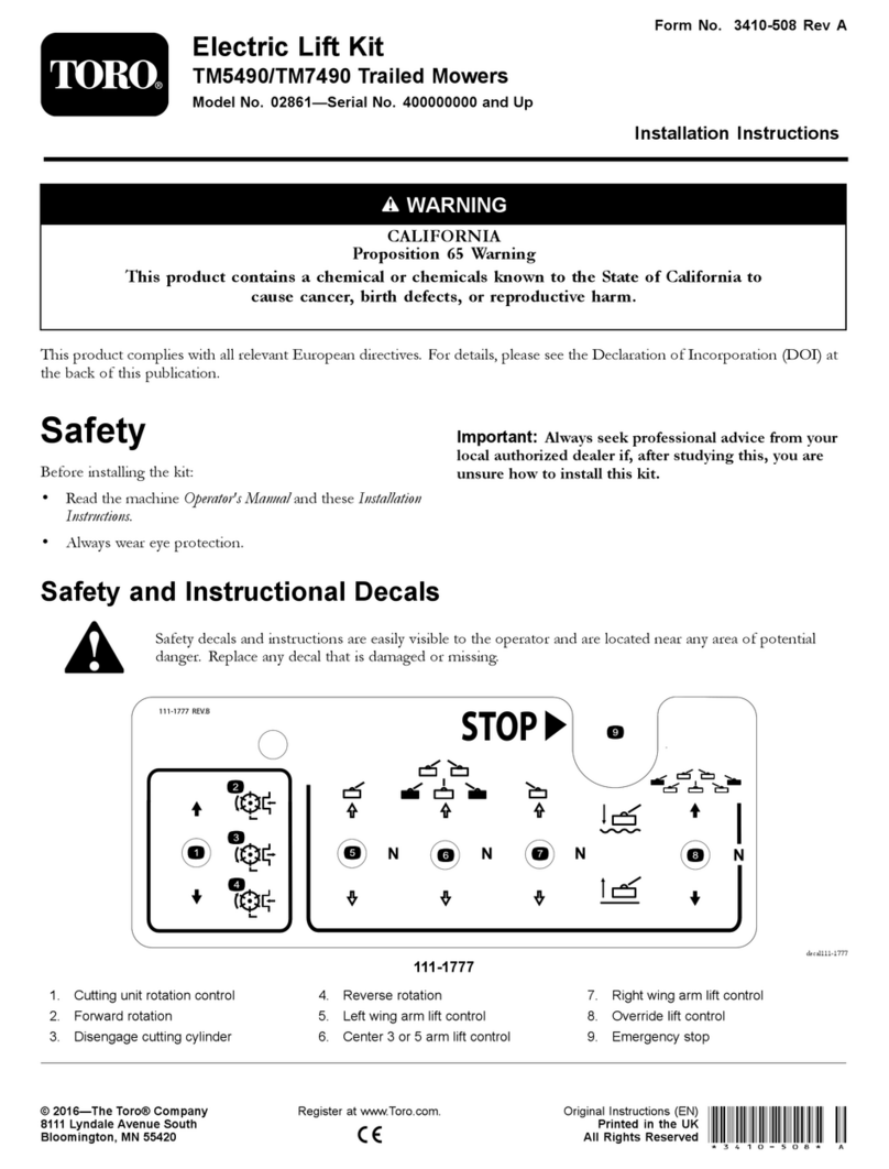
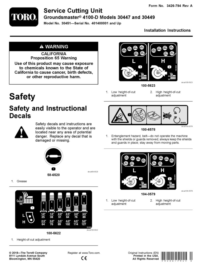
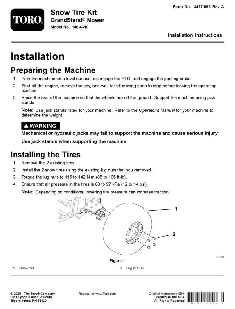
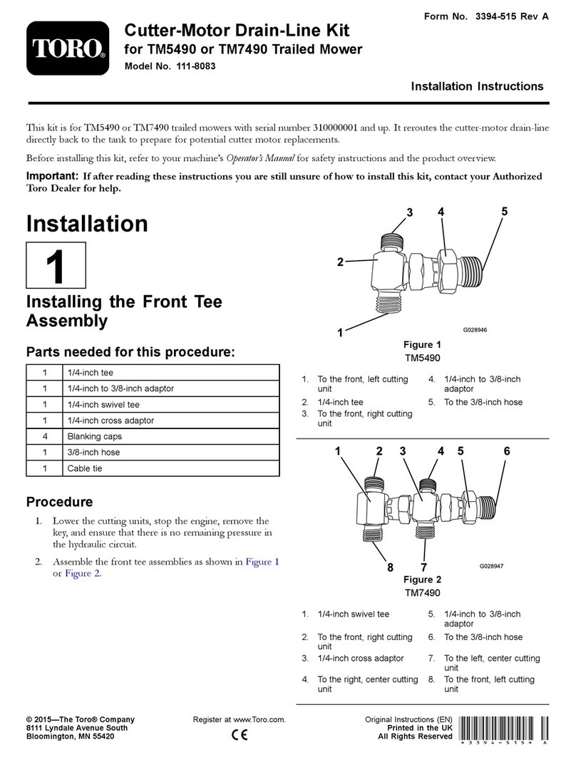
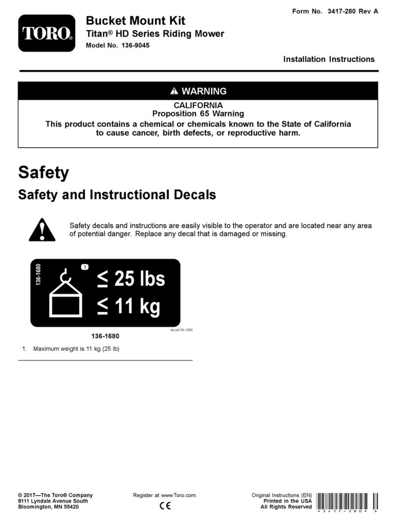
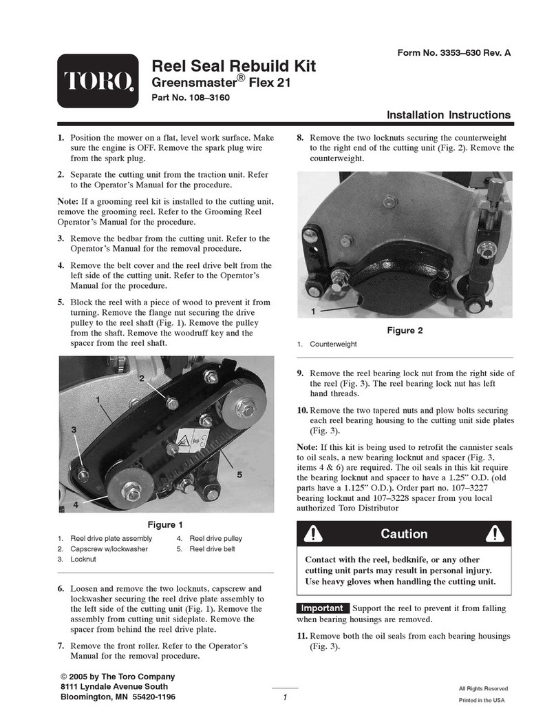
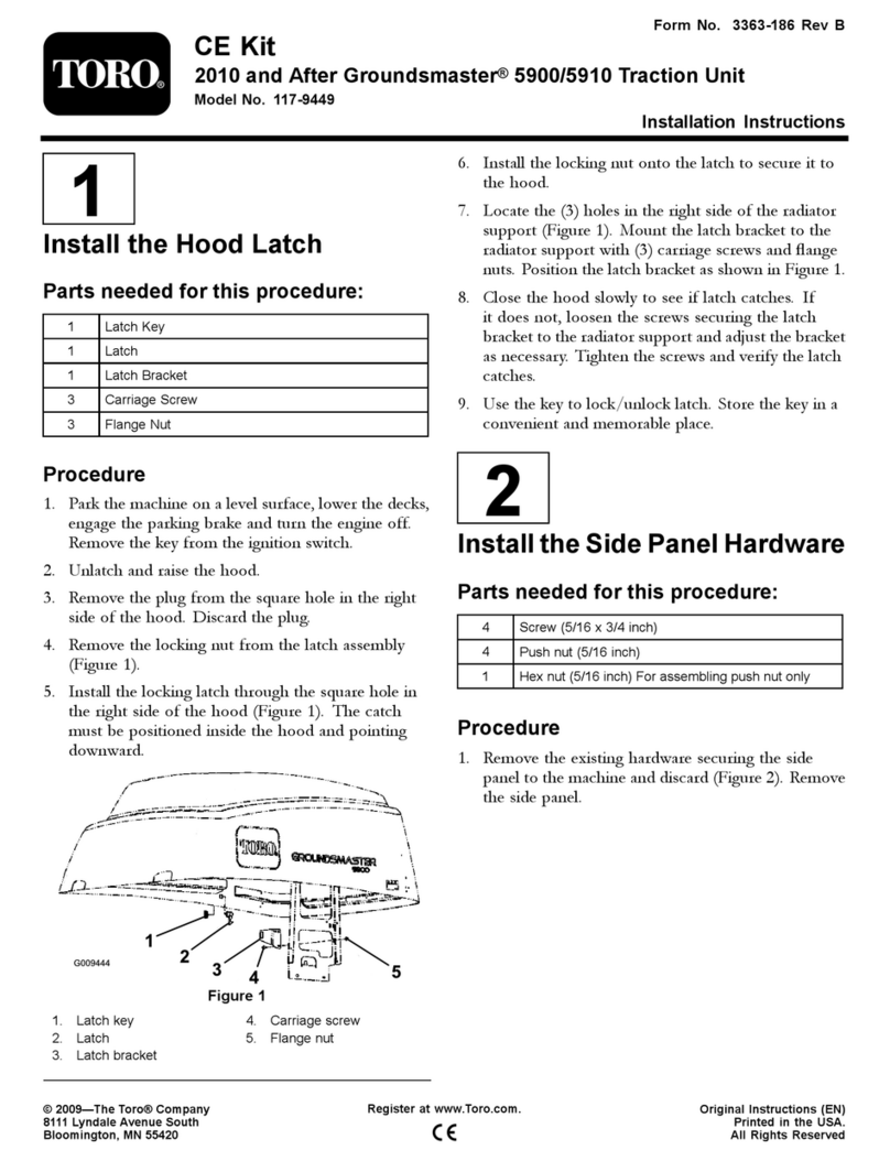
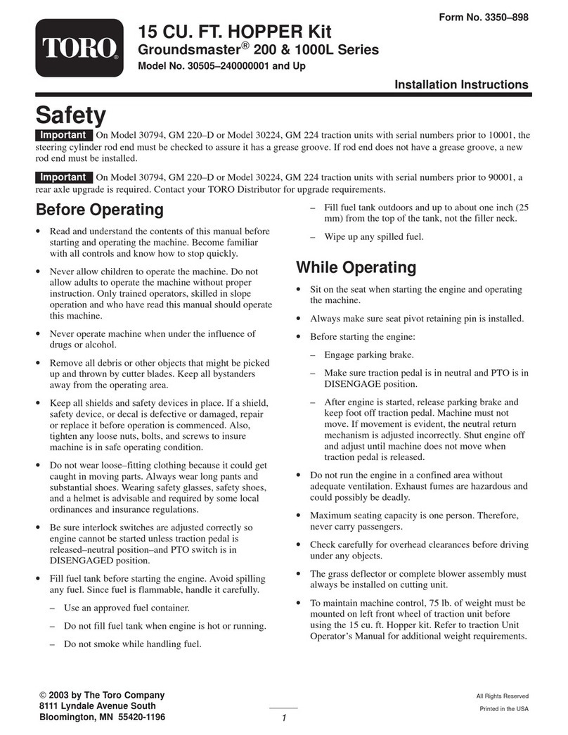
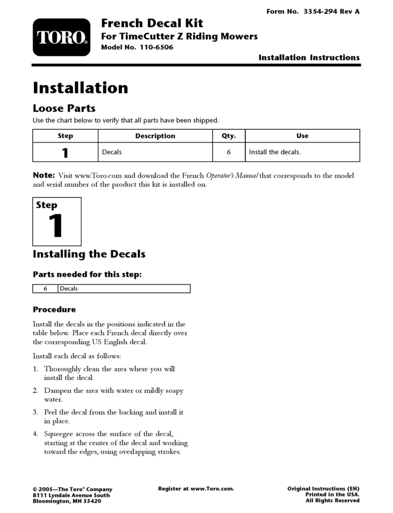
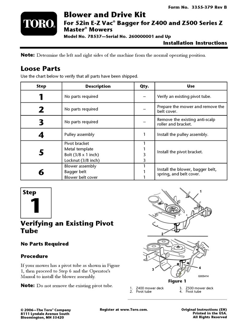
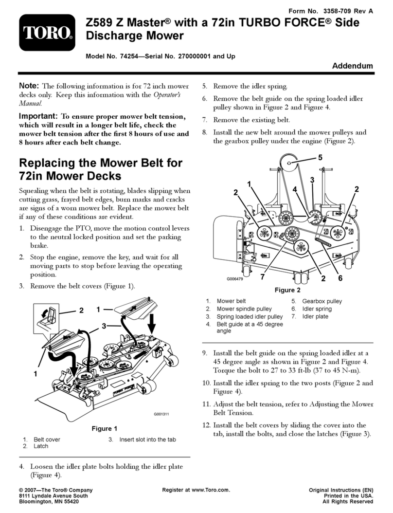
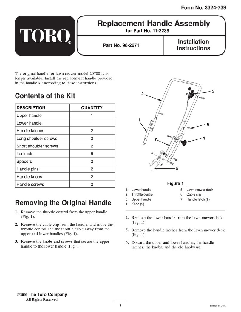
Toro Groundsmaster 4500-D User manual

FormNo.3408-266RevE
CabKit
SerialNumber315000001andAfterGroundsmaster®4500/4700-D
orReelmaster®7000-DTractionUnit
ModelNo.30901—SerialNo.400000000andUp
Operator'sManual
Note:Theweightofthecabis318kg(700lb).Youneedaliftwitharatingof340kg(750lb)forliftingthecab.
Safety
ThisproductcomplieswithallrelevantEuropeandirectives.Fordetails,pleaseseetheDeclarationof
Incorporation(DOI)atthebackofthispublication.
SafetyandInstructional
DecalsSafetydecalsandinstructionsare
easilyvisibletotheoperatorandare
locatednearanyareaofpotential
danger.Replaceanydecalthatis
damagedormissing.
decal120-0250
120-0250
1.Slow-movingvehicle
decal130-0594
130-0594
1.Warning—readtheOperator’sManual;whensittinginthe
cab,alwayswearaseatbelt;wearhearingprotection.
©2022—TheToro®Company
8111LyndaleAvenueSouth
Bloomington,MN55420
Registeratwww.T oro.com.OriginalInstructions(EN)
PrintedintheUSA
AllRightsReserved*3408-266*

decal130-5355
130-5355
1.Closetherearwindow.2.Raisethehood.
decal132-3253
132-3253
1.Movethesteeringcolumn
totheforwardposition.
4.Lowertheseatback.
2.Raisetheseatto
maximumheight.
5.Tilttheseatsideways.
3.Movetheseatforward.
decal130-0611
130-0611
1.Warning—1)Removethepin;2)Raisethewindows;3)
Exitthecab.
Setup
LooseParts
Usethechartbelowtoverifythatallpartshavebeenshipped.
ProcedureDescriptionQty.Use
1Nopartsrequired–Preparethemachinebeforeyouinstall
thecabunit.
Left,frontmount1
Right,frontmount1
Left,rearmount1
Right,rearmount1
2
Rubberisolator4
Preparethecabmountinghardware.
Left,frontfoamseal1
Center,frontfoamseal1
Right,frontfoamseal1
Leftfoamseal1
Rightfoamseal1
Lefttankfoam1
Righttankfoam1
Left,rearfoamseal1
Right,rearfoamseal1
3
Rearfoamseal1
Applythefoamsealstothemountand
frame.
2

ProcedureDescriptionQty.Use
Left,frontmount1
Right,frontmount1
Bolt(3/8x1inch)7
Flangenut(3/8inch)5
Locknut(3/8inch)2
Left,rearmount1
4
Right,rearmount1
Installthemountstothemachine.
Cab1
Bolt(1/2x3-1/4inch)4
Washer(2-1/4inches)4
Washer(1-3/8inches)2
5
Locknut(1/2inch)4
Installthecabunittothemachine.
Left,rearpanelassembly1
Right,rearpanelassembly1
Bolt(1/4x3/4inch)6
Clipnut4
Flangenut(1/4inch)2
Upholsterypanel1
Insulationblanket1
6
Floortread1
Installthepanelsandoor.
Fitting(3/8NPTx0.625barb)2
Hoseclamp2
Right-angletting(3/4inch)1
Right-angletting(7/8inch)1
7
R-Clamp2
Installthehoses.
Washertank1
Tankmount1
Tankplate1
Carriagebolt(5/16x3/4inch)4
Flangenut(5/16inch)4
Swelllatch1
Swell-latchbushing1
Swell-latchnut1
8
R-Clamp1
Installthewashertankandmount.
9Cabletie5Connectthewireharness.
10Safetydecal1Applythesafetydecaltotherear
window.
11Nopartsrequired–Completetheinstallation.
3

1
PreparingtheMachine
NoPartsRequired
PositioningtheMachine
1.Clearalocationinyourworkspaceunderthe
hoistsystem.
Note:Verifythatyourhoistsystemiscapableof
safelysupportingthecabunitoverthemachine
duringtheinstallation.
2.Movethemachineunderneaththehoistand
engagetheparkingbrake.
3.Shutofftheengineandremovethekey.
4.Chockthewheelstopreventthemachinefrom
movingduringtheinstallation.
5.Removethebattery;refertotheOperator’s
Manual.
RemovingtheBattery
WARNING
Incorrectbatterycableroutingcoulddamage
themachineandcables,causingsparks.
Sparkscancausethebatterygassesto
explode,resultinginpersonalinjury.
•Alwaysdisconnectthenegative(black)
batterycablebeforedisconnectingthe
positive(red)cable.
•Alwaysconnectthepositive(red)battery
cablebeforeconnectingthenegative
(black)cable.
1.Unlatchandraisetheoperator'sconsolepanel
(Figure1).
g009985
Figure1
1.Operator'sconsolepanel2.Latch
2.Removetherubberbootsfromthebattery
terminals.
3.Removethenegativecable(black)fromthe
negative(-)terminalandthepositivecable(red)
fromthepositive(+)terminalofthebattery
(Figure2).
g009986
Figure2
1.Positive(+)terminal2.Negative(-)terminal
4.Removeandretainthebattery.
4

RemovingtheRollBarTopBolts
Important:Useanassistanttosupporttheroll
barwhenyouremovetheboltssecuringittothe
machine.
1.Removeandretaintheboltsecuringthestorage
compartmentlocatedontheleftsideofthe
machine(Figure3).
g030642
Figure3
1.Bolt2.Storagecompartment
2.Removeandretainthestoragecompartment.
3.Removeandretainthe2bolts,reinforcement
plate,and2angenutssecuringtherollbarto
thetopoftheframe(Figure4).
g030899
Figure4
1.Bolt3.Reinforcementplate
2.Rollbar4.Flangenut
4.Removeandretainthescrewsecuringthe
reinforcementplateandtheboltsecuringthe
batterycompartment(Figure5).
g030670
Figure5
1.Screw2.Bolt
5.Removeandretaintheboltandthe
battery-compartmentclamp(Figure6).
g030672
Figure6
1.Battery-compartmentclamp
2.Bolt
6.Arrangethereinforcementplateandbattery
compartmenttoallowyoutoremovethe2bolts,
reinforcementplate,and2angenutsthat
securetherollbartothetopoftheframe(Figure
7).Setthemaside.
5

g030900
Figure7
1.Bolt3.Reinforcementplate
2.Rollbar4.Flangenut
RemovingtheRollBar
Important:Useanassistanttosupporttheroll
barwhenyouremovetheboltssecuringittothe
machine.
1.Removetheboltssecuringtherollbartotheleft
sideofthemachine(Figure8).
g030675
Figure8
1.Bolts2.Rollbar
2.Useanassistanttohelpyouremovetherollbar
fromthemachine.
3.Storetherollbar.
6

2
PreparingtheCabMounts
Partsneededforthisprocedure:
1Left,frontmount
1Right,frontmount
1Left,rearmount
1Right,rearmount
4Rubberisolator
PreparingtheFrontMount
Pressarubberisolatorintoeachholeinthefront
mounts(Figure9).
g030678
Figure9
1.Rubberisolators3.Right,frontmount
2.Left,frontmount
Note:Usesoapywaterandamallettoassistwith
insertingtherubberisolatorsintotheholes.
DrillingtheFrontMountHoles
Followthisprocedureonlyifnecessary.
Locateanddrill2holes(13/32inchdiameter)forthe
right,frontmountasshowninFigure10.
g030684
Figure10
1.Hole(13/32inchdiameter)4.21mm(0.83inch)
2.52mm(2.07inches)5.23mm(0.89inch)
3.17mm(0.67inch)
PreparingtheRearMounts
1.Pressarubberisolatorintotheholeoftheleft,
rearmountonthecabframe(Figure11).
g030685
Figure11
1.Rubberisolator2.Left,rearmount
2.Pressarubberisolatorintotheholeoftheright,
rearmountonthecabframe(Figure12).
7

g030686
Figure12
1.Rubberisolator2.Right,rearmount
Note:Usesoapywaterandamallettoassistwith
insertingtherubberisolatorintothehole.
3
ApplyingtheFoamSeals
Partsneededforthisprocedure:
1Left,frontfoamseal
1Center,frontfoamseal
1Right,frontfoamseal
1Leftfoamseal
1Rightfoamseal
1Lefttankfoam
1Righttankfoam
1Left,rearfoamseal
1Right,rearfoamseal
1Rearfoamseal
ApplyingtheFrontFoamSeals
Applythecenter,frontfoamsealandthentheleft,
frontandright,frontfoamsealsapproximately3mm
(1/8inch)fromtheedgeonthefrontofthecabunit
(Figure13).
g030692
Figure13
1.Applicationarea3.Center,frontfoamseal
2.Left,frontfoamseal4.Right,frontfoamseal
Note:Installtheendsofthefoamsealstointerlock
andcreateasolidseal.
ApplyingtheSideFoamSeals
1.Applytheleftfoamsealapproximately3mm
(1/8inch)fromtheedgeonthefront,leftsection
ofthecabunit(Figure14).
Note:Installtheendsofthefoamsealsto
interlockandcreateasolidseal.
g030702
Figure14
1.Applicationarea2.Leftfoamseal
2.Applytherightfoamsealapproximately3mm
(1/8inch)fromtheedgeontheright,front
sectionofthecabunit.
Note:Installtheendsofthefoamsealsto
interlockandcreateasolidseal.
8

3.Removethepaperbackingfromthe
double-facedtapeonbothsidesofthecabunit
(Figure15).
g030703
Figure15
1.Double-facedtape2.Lefttankfoam
4.Applythelefttankfoamtothecabunit(Figure
15).
5.Applytherighttankfoamtothecabunit.
ApplyingtheRearFoamSeals
1.Removethepaperbackingfromthe
double-facedtapeatthebackofthecabunit
(Figure16).
g034905
Figure16
1.Left,rearfoamseal3.Right,rearfoamseal
2.Double-facedtape
2.Applytheleft,rearandright,rearfoamsealsto
thecabunit(Figure16).
3.Applytherearfoamsealtothebackofthecab
unit(Figure17).
g030708
Figure17
1.Rearfoamseal2.Applicationarea
4
InstallingtheCabMounts
Partsneededforthisprocedure:
1Left,frontmount
1Right,frontmount
7Bolt(3/8x1inch)
5Flangenut(3/8inch)
2Locknut(3/8inch)
1Left,rearmount
1Right,rearmount
InstallingtheLeftFrontMount
1.Removetheexistinghardwareandusethe3
bolts(3/8x1inch)andangenutstosecurethe
mounttothemachine(Figure18).
9

g030713
Figure18
1.Bolt(3/8x1inch)3.Flangenut(3/8inch)
2.Leftmount
2.Torquetheboltsandnutsto37to45N∙m(27
to33ft-lb).
InstallingtheRightFrontMount
1.Removetheexistinghardwareandusethe4
bolts(3/8x1inch)2angenuts,and2locknuts
tosecurethemounttothemachine(Figure19).
g030714
Figure19
1.Flangenut(3/8inch)3.Leftmount
2.Locknut4.Bolt(3/8x1inch)
2.Torquetheboltsandnutsto37to45N∙m(27
to33ft-lb).
InstallingtheLeftRearMount
1.Usethenewhardwaretosecuretheleftrear
mounttotheframe(Figure20).
g030716
Figure20
1.Bolt(1/2x6inches)4.Reinforcementplate
2.Leftmount5.Bolt(1/2x1-1/4inches)
3.Flangenut
2.Torquethebolts(1/2x6inches)andnutsto91
to113N∙m(67to83ft-lb).
3.Torquethebolts(1/2x1-1/4inches)to91to113
N∙m(67to83ft-lb).
InstallingtheRightRearMount
1.Usethenewhardwaretosecuretherightrear
mounttotheframe(Figure21).
g030717
Figure21
1.Bolt(1/2x6inches)4.Flangenut
2.Rightmount5.Reinforcementplate
3.Bolt(1/2x1-1/4inches)
2.Torquethebolts(1/2x6inches)andnutsto91
to113N∙m(67to83ft-lb).
3.Torquethebolts(1/2x1-1/4inches)to91to113
N∙m(67to83ft-lb).
10

4.Usethebolt(5/16x1-1/2inches)tosecurethe
storagecompartmenttothemachine(Figure
22).
g030718
Figure22
1.Bolt(5/16x1-1/2inches)2.Storagecompartment
5.Usethescrewtosecurethereinforcementplate
tothemachineandusethebolt(1/2x1inch)to
securethebattery-compartmentclampandthe
batterycompartmenttothemachine(Figure23).
g030719
Figure23
1.Screw3.Battery-compartment
clamp
2.Batterycompartment4.Bolt(1/2x1inch)
InstallingtheWireHarnessand
PreparingtheCabforInstallation
Routethewireharnessfromunderneaththemachine
uptothebatteryboxasshowninFigure24.
g033196
Figure24
InstallthewireharnessasshowninFigure25.
g385502
Figure25
UsethemeasurementsinFigure26anddrillholes
intothecab.
g032999
Figure26
1.1.93inches4.3.87inches
2.Hole(0.31inchdiameter)5.Hole(0.31inchdiameter)
3.3.36inches6.2.29inches
11

5
InstallingtheCabUnitto
theMachine
Partsneededforthisprocedure:
1Cab
4Bolt(1/2x3-1/4inch)
4Washer(2-1/4inches)
2Washer(1-3/8inches)
4Locknut(1/2inch)
Procedure
1.Usethe4liftpointstosupportthecababove
themachine(Figure27).
Note:Ensurethattheliftingtooldoes
notcontactthecabrooforheadlinerwhen
supportingthecab.
g030873
Figure27
1.Hoistbar3.Rearliftpoint
2.Frontliftpoint
2.Lowerthecabtothemachine,aligningthe4bolt
holesonthemounts.
3.Useabolt(1/2x3-1/4inch),washer(2-1/4
inches),andlocknut(1/2inch)tosecurethecab
totherearmountsonthemachine(Figure28).
g030727
Figure28
1.Bolt(1/2x3-1/4inch)3.Rearmount
2.Washer(2-1/4inches)4.Locknut(1/2inch)
4.Torquethebolt(1/2x3-1/4inch)andlocknut
(1/2inch)to129to156N∙m(95to115ft-lb).
Note:Ensurethatthereisasmallamountof
slackintheliftingtooltoallowthecabtosettle
ontothemachine.
5.Useabolt(1/2x3-1/4inch),washer(1-3/8
inches),washer(2-1/4inches),andlocknut(1/2
inch)tosecurethecabtothefrontmountson
themachine(Figure29).
g030728
Figure29
1.Bolt(1/2x3-1/4inch)4.Washer(2-1/4inches)
2.Washer(1-3/8inches)5.Locknut(1/2inch)
3.Frontmount
6.Torquethebolt(1/2x3-1/4inch)andlocknut
(1/2inch)to129to156N∙m(95to115ft-lb)and
disconnecttheliftingtoolfromthecab.
12

6
InstallingthePanelsand
Flooring
Partsneededforthisprocedure:
1Left,rearpanelassembly
1Right,rearpanelassembly
6Bolt(1/4x3/4inch)
4Clipnut
2Flangenut(1/4inch)
1Upholsterypanel
1Insulationblanket
1Floortread
InstallingRearPanelAssembly
1.Installthe2clipnutsontothecabframe(Figure
30).
g030909
Figure30
1.Cabframe3.Left,rearpanelassembly
2.Clipnut4.Bolt(1/4x3/4inch)
2.Securethepanelassemblytothecabusingthe
2bolts(1/4x3/4inch)asshowninFigure30.
3.Use1bolt(1/4x3/4inch)and1angenut(1/4
inch)tocompletetheinstallationofthepanel
assembly(Figure31).
g030922
Figure31
1.Bolt(1/4x3/4inch)2.Flangenut
4.Torquetheboltsandnutto10to12N∙m(90to
110in-lb).
5.Repeatthepreviousstepstotherightsideof
thecab.
InstallingtheBackPanel
1.Ensuretheinstallationareaisclean.
2.Aligntheupholsterypanelwiththecenterof
thebackpanelinsidecabtoverifyitstand
placement(Figure32).
Note:Rememberormarkwherethecornerof
theupholsterypanelbeginswhenitiscentered
acrossthebackpanelofthecab.
g030729
Figure32
1.Cab2.Upholsterypanel
3.Remove1sectionofthebackingtoexposethe
adhesive.
13

4.Startwiththeuppercorneroftheupholstery
panelandadhereittothebackofthecabso
thatitiscenteredonceitiscompletelyinstalled.
5.Adherethepanel,1sectionatatime,fromone
endtotheother,untiltheupholsterypanelis
completelyapplied.
InstallingtheInsulationBlanket
1.Removetheinsulationblanketfromtheshipping
tube.
Note:Donotunrolltheinsulationblanketuntilit
isinposition.
2.Positiontheblanketacrossthestorage
compartmentsbehindtheoperator’sseat.
3.Tuckintheedgesoftheblanketaroundthe
operator’sseatasyouunrollittowardthefront
ofthemachine.
4.Removethebackingfromtheadhesiveonthe
hookandloopstripsattheendoftheblanket
andadherethestripswheretheylie.
Note:Ensurethesurfacewheretheadhesive
backedhookandloopstripadherestothe
platformisclean.
5.Adherethehookandloopstripsrmlytothe
platform.
InstallingtheFloorTread
1.Ensurethattheinstallationareaisclean.
2.Installtheoortreadontotheplatforminside
thecab.
g030849
Figure33
1.Floortread
3.Ensurethattheboltheadsontheplatformare
alignedwiththecutoutsintheoortread.
7
ConnectingtheHoses
Partsneededforthisprocedure:
2Fitting(3/8NPTx0.625barb)
2Hoseclamp
1Right-angletting(3/4inch)
1Right-angletting(7/8inch)
2R-Clamp
ConnectingtheHeaterHoses
1.Applysealanttothetting(3/8NPTx0.625
barb);skippingtherstthread.
2.Removetheheatersupplyandreturnhose
plugsfromtheengineandinstallthettings(3/8
NPTx0.625barb)asshowninFigure34.
g303473
Figure34
1.Fitting(3/8NPTx0.625
barb)
3.Fitting(3/8NPTx0.625
barb)
2.Returnhoseplug4.Supplyhoseplug
3.Tightenthettings(3/8NPTx0.625barb)2to3
turnspastnger-tight.
4.Routethehosesfortheheaterandthedrain
hosethroughthehoseringontherearcab
mount(Figure35).
14

g030761
Figure35
1.Hosering3.Heaterhose
2.Drainhose4.Drainhose
5.Slidethehoseclampoverthesupplyhoseand
theninsertthehoseoverthetting(3/8NPTx
0.625barb)asshowninFigure36.
Note:Thesupplyhoseisdesignatedbyared
plugat1endoftheassembly.Removetheplug
beforeinstallingthehose.
g030737
Figure36
1.Heater-supplyhose3.Barbtting
2.Hose-clamp
6.Slidethehose-clampoverthereturnhoseand
theninsertthehoseoverthetting(3/8NPTx
0.625barb)asshowninFigure37.
Note:Thereturnhoseisdesignatedbyagreen
plugat1endoftheassembly.Removetheplug
beforeinstallingthehose.
g030760
Figure37
1.Heater-returnhose3.Barbtting
2.R-clamp4.Hoseclamp
15

InstallingtheAir-Conditioner
Fittings
Note:ThoroughlylubricatetheO-ringbefore
installingthettingswithPAGOil46oranequivalent
lubricant.
1.Removetheexhaustpipe,muferbracket,and
enginefan(Figure38).
g384459
Figure38
1.Enginefan3.Muferbracket
2.Fanbolts
2.Installtheright-angletting(7/8inch)andO-ring
(size8)tothelow-pressureorsuctionporton
theair-conditioningpump(Figure39).
Note:Ensurethettingsareinstalledatthe
anglesshowninFigure40andFigure41.
g032993
Figure39
1.Right-angletting(3/4
inch)
4.O-ring(size10)
2.O-ring(size8)5.Air-conditioningpump
3.Right-angletting(7/8
inch)
3.Torquethettingto34to47N∙m(25to35ft-lb)
4.Installtheright-angletting(3/4inch)andO-ring
(size10)tothehigh-pressureordischargeport
ontheair-conditioningpump(Figure39).
5.Torquethettingto34to47N∙m(25to35ft-lb)
6.Positionthecompressorintothemachineand
secureitasshownintheAirConditionerKit
(ModelNo.30877)instructions.
7.Installtheenginefan,muferbracket,and
exhaustpipe(Figure38).
ConnectingtheAir-Conditioning
Hoses
1.Connecttheair-conditioninglow-pressurehose
(7/8inch)fromthecabunittotheright-angle
tting(7/8inch)asshowninFigure40.
g385530
Figure40
1.Right-angletting(3/4
inch)
2.Right-angletting(7/8
inch)
2.Torquethettingto34to47N∙m(25to35ft-lb)
16

3.Connecttheair-conditioninghigh-pressurehose
(3/4inch)fromthecabtotheright-angletting
(3/4inch)asshowninFigure41.
g033198
Figure41
4.Torquethettingto34to47N∙m(25to35ft-lb)
5.Install1R-clamparoundeachair-conditioning
hoseandusethe2existingboltstosecurethem
tothemachineframe(Figure42).
g030768
Figure42
1.High-pressurehose3.Bolt(5/16x1inch)
2.Low-pressurehose4.R-clamp
8
InstallingtheWasherTank
Partsneededforthisprocedure:
1Washertank
1Tankmount
1Tankplate
4Carriagebolt(5/16x3/4inch)
4Flangenut(5/16inch)
1Swelllatch
1Swell-latchbushing
1Swell-latchnut
1R-Clamp
InstallingtheWasherTankand
Mount
1.Use2carriagebolts(5/16x3/4inch)and2
angenuts(5/16inch)tosecurethetankplate
tothecoolant-bottlesupport(Figure43)
g030730
Figure43
1.Coolant-bottlesupport3.Tankplate
2.Carriagebolt(5/16x3/4
inch)
4.Flangenut(5/16inch)
2.Torquetheboltandnutto1,978to2,542N∙cm
(175to225in-lb).
3.Use2carriagebolts(5/16x3/4inch)and2
angenuts(5/16inch)tosecurethewasher
17

bottleandR-clamptothetankmount(Figure
44).
g030732
Figure44
1.Tankmount4.R-clamp
2.Flangenut(5/16inch)5.Carriagebolt(5/16x3/4
inch)
3.Washerbottle
4.Installtheswell-latchassemblytothetank
mount(Figure45).
g030919
Figure45
1.Swelllatch3.Swell-latchnut
2.Swell-latchbushing
5.Insertthetabintotheslotandtheswell-latch
bushingintotheholeinthetankplate(Figure
46).
g030920
Figure46
1.Swelllatch2.Tankmount
6.Fliptheswell-latchleverdown(Figure46).
Note:Theswelllatchshouldholdthetank
mountrmlytothetankplate.Adjustthenutto
changethepressureappliedbytheswelllatch.
ConnectingtheWasherHose
1.Routethewasherhosethroughthehoseringon
therearcabmount(Figure47).
g030762
Figure47
1.Hosering2.Washerhose
2.RoutethewasherhosethroughtheR-clamp
andconnectittothewasherbottle(Figure48).
18

g030733
Figure48
1.Washerhose3.R-clamp
2.Bottleconnection
9
ConnectingtheWire
Harness
Partsneededforthisprocedure:
5Cabletie
Procedure
1.Connectthewireharnessfromthecabtothe
wireharnessontherightsideofthemachine
(Figure49).
g030776
Figure49
1.Wireharnessfromthemachine
2.Wireharnessfromthecab
2.Connectthecabpowerconnectortothe
connectorontherightsideofthemachine
(Figure50).
19

g030779
Figure50
1.Connectorfromthemachine
2.Connectorfromthecab
3.Connectthewirefromtheair-conditioner
compressortothebulletconnectoronthewire
harness(Figure51).
g030788
Figure51
1.Compressorwire3.Wireharness
2.Bulletconnector
4.Routethewireharnessforthewasherbottle
throughtheR-clampandconnectittothebottle
(Figure52).
g030777
Figure52
1.Wireharnessconnector2.Washerbottleconnection
5.Usecabletiestosecurethewireharnesstothe
hydraulichosesandhardlinesatthelocations
showninFigure53andFigure54.
g030778
Figure53
1.Wireharness2.Cabletie
20
Other manuals for Groundsmaster 4500-D
16
This manual suits for next models
2
Table of contents
Other Toro Lawn Mower Accessories manuals