Toro 09930 User manual

FormNo.3368-805RevC
ProCoreSR48,SR54,SR54–S,
SR70,SR70–S,SR72andSR75
Aerators
ModelNo.09930—SerialNo.311000001andUp
ModelNo.09931—SerialNo.311000001andUp
ModelNo.09932—SerialNo.311000001andUp
ModelNo.09933—SerialNo.311000001andUp
ModelNo.09934—SerialNo.311000001andUp
ModelNo.09935—SerialNo.311000001andUp
ModelNo.09936—SerialNo.311000001andUp
ToregisteryourproductordownloadanOperator'sManualorPartsCatalogatnocharge,gotowww.Toro.com.OriginalInstructions(EN)

Introduction
Readthisinformationcarefullytolearnhowtooperate
andmaintainyourproductproperlyandtoavoidinjury
andproductdamage.Youareresponsibleforoperating
theproductproperlyandsafely.
YoumaycontactTorodirectlyatwww .Toro.comfor
productandaccessoryinformation,helpndingadealer,
ortoregisteryourproduct.
Wheneveryouneedservice,genuineToroparts,
oradditionalinformation,contactanAuthorized
ServiceDealerorToroCustomerServiceandhave
themodelandserialnumbersofyourproductready.
Figure1identiesthelocationofthemodelandserial
numbersontheproduct.Writethenumbersinthe
spaceprovided.
Figure1
1.Modelandserialnumberlocation
ModelNo.
SerialNo.
Thismanualidentiespotentialhazardsandhassafety
messagesidentiedbythesafetyalertsymbol(Figure2),
whichsignalsahazardthatmaycauseseriousinjury
ordeathifyoudonotfollowtherecommended
precautions.
Figure2
1.Safetyalertsymbol
Thismanualuses2otherwordstohighlightinformation.
Importantcallsattentiontospecialmechanical
informationandNoteemphasizesgeneralinformation
worthyofspecialattention.
©2011—TheToro®Company
8111LyndaleAvenueSouth
Bloomington,MN554202
Contactusatwww.Toro.com.
PrintedintheUSA.
AllRightsReserved

Contents
Introduction.................................................................2
Safety...........................................................................4
SafeOperatingPractices.......................................4
SafetyandInstructionalDecals.............................6
Setup...........................................................................8
1RemovingtheAeratorfromtheCrating..............9
2ConnectingtheLowerLinkArms......................9
3ConnectingtheHydraulicTopLink
(ModelsSR48,SR54,SR70,SR72and
SR75).............................................................10
4ConnectingtheTractorUpperLink(Models
SR54–SandSR70–S)......................................12
5VerifyingtheHydraulicTopLinkSet
Up..................................................................12
6CheckingthePTOAngle.................................13
7FittingthePTOshaft.......................................14
8InstallingthePTOShield.................................15
9ConnectingthePTOShaft...............................16
10AdjustingtheSwayLinks................................17
11LevelingtheAeratorSide-to-Side...................18
12InstallingtheTines.........................................18
13SettingtheTineDepth(ModelsSR54–S
andSR70–S)...................................................18
14InstallingtheRearGuard................................19
15InstallingtheLatchLock................................20
16RemovingtheStorageStands(ModelsSR54
andSR70)......................................................20
17RemovingtheStorageStands(ModelsSR48
andSR72).......................................................21
ProductOverview......................................................22
Specications.....................................................22
Attachments/Accessories...................................22
Operation...................................................................23
TractorControls.................................................23
PrinciplesofOperation......................................23
TractorPTOSpeed............................................23
TrainingPeriod...................................................23
BeforeAerating..................................................23
AeratingProcedures...........................................24
OperatingTips...................................................24
SubsoilCultivation.............................................25
HardGround.....................................................25
Longer/LargerTines..........................................25
MultiRowAdapterHeads..................................25
RootZoneLifting..............................................25
UsingtheHoodPropRodsModelSR75
only................................................................25
AdjustingtheTineAngle....................................26
AdjustingtheTineDepth(ModelsSR54–S
andSR70–S)...................................................27
TransportOperation..........................................27
InspectionandCleanupafterUse........................28
Maintenance...............................................................29
RecommendedMaintenanceSchedule(s)................29
LiftingtheMachine............................................29
GreasingtheBearings.........................................30
CheckingtheGearboxOil..................................30
ChangingtheGearboxOil..................................31
Inspecting/AdjustingtheDriveChain................31
AdjustingthePTOClutch..................................32
FastenerTorqueSpecications............................32
CheckingtheSprings..........................................33
AdjustingtheHoleSpacing.................................33
RemovingtheAeratorfromtheTractor...............33
TroubleShooting...............................................34
Storage.......................................................................35
3

Safety
Improperuseormaintenancebytheoperatoror
ownercanresultininjury.Toreducethepotential
forinjury,complywiththesesafetyinstructions
andalwayspayattentiontothesafetyalert
symbol,whichmeansCAUTION,WARNING,or
DANGER-"personalsafetyinstruction."Failureto
complywiththeinstructionmayresultinpersonal
injuryordeath.
SafeOperatingPractices
BeforeOperating
•OwnersofthisAeratormustgiveoperatorsand
employeesfulloperationandsafetyinstructions
beforeallowingthemtooperatethismachineandat
leastannuallythereafter.Anoperatorwhohasnot
readandfullyunderstoodalloperatingandsafety
instructionsisnotqualiedtooperatethismachine.
Becomefamiliarwithallcontrolsandknowhowto
stopquickly.
•Donotallowchildrentooperatethemachine.Do
notallowadultstooperatethemachinewithout
properinstruction.
•Removealldebrisorotherobjectsthatmight
interferewithoperation.Keepallbystandersaway
fromtheworkarea.
•Locateandmarkallundergroundobstructionssuch
asirrigationcomponents,electricalortelephone
lines.
•Makesuretractorisinneutralandparkingbrake
appliedbeforestarting.RefertoTractorOperator's
Manualforsafestartingprocedures.
•Ensurethatyourtractorissuitableforusewithan
implementofthisweightbycheckingwithyour
tractorsupplierormanufacturer.
•Mountingtheaeratortotherearofthetractorwill
decreasetheweightonthetractorfrontaxle.To
assureadequatesteeringcontrolandstabilityitmay
benecessarytoaddballasttothefrontofthetractor.
RefertoTractorOperator'sManualforballast
requirements.
•Keepallshieldsandsafetydevicesinplace.Ifa
shield,safetydeviceordecalisdamaged,repairor
replaceitbeforeoperationiscommenced.Also
tightenanyloosenuts,boltsandscrewstoensure
machineisinsafeoperatingcondition.
•Donotoperatemachinewhilewearingsandals,
tennisshoes,sneakersorshorts.Also,donotwear
loosettingclothingwhichcouldgetcaughtin
movingparts.Alwayswearlongpantsandsubstantial
shoes.Wearingsafetyglasses,safetyshoes,hearing
protectionandahelmetisadvisableandmaybe
requiredbysomelocalordinancesandinsurance
regulations.
WhileOperating
•Neveroperatethetractorinreversewhentheaerator
islowered.
•Keepallbystandersandpetsawayfromthework
area.
•Usingthemachinedemandsattention,andto
preventlossofcontrol:
–Useonlyindaylightorwhenthereisadequate
articiallight.
–Watchforholesorotherhiddenhazards.
–Donotoperatethemachineclosetoasandtrap,
ditch,creekorotherhazard.
–Reducespeedonsidehillsandbeforemaking
sharpturnstopreventtippingorlossofcontrol.
–Lookbehindtheaeratorbeforebackingup.
•Ifthetinesstrikeasolidobjectorthemachine
vibratesabnormally,disengagethePTO,setthe
parkingbrakeandshuttheengineoff.Removekey
fromignitionswitch.Checkaeratorandtractionunit
fordamage.Repairanydamagebeforerestartingthe
engineandoperatingthetines.Besuretinesarein
goodconditionandallboltsaretight.
•Beforeleavingmachineunattended,disengagepower
toaerator,loweraeratorontostoragestandsandset
parkingbrake.Stopengine.
•Neverdismountwhiletractorisinmotion.Never
getonorofftractorwhileengineisrunningand
PTOdriveshaftisengaged.NeverstepoverPTO
shafttoreachothersideofaerator-walkaround
themachine.
•Whenliftingtheaerator,disengagethePTOwhen
therollerisapproximately5inchesfromtheground.
•Donotoperatethismachinewithouttherolleron
theground.Neveroperatewiththemachinein
theraisedposition.
•Parktheaeratoronahard,levelsurface,installthe
aeratorstoragestandsbeforedisconnectingfrom
tractor.
•Ifitisnecessarytoprobebelowthesoilsurface,use
anonconductivematerialtopreventelectricalshock
incaseelectricalwiresarepresent.
•Alwayslowertheaeratortothegroundbefore
leavingthetractorunattended.Neverleavethe
aeratorintheraisedpositionwhenitisunattended.
4

Transporting
•Theaeratorisheavy.Whenattachedtoatractor
andintheraisedposition,itsweightwillaffect
stability,brakingandsteering.Exercisecautionwhen
transportingbetweenworkingareas.
•Alwaysmaintainpropertractortirepressure.
•Besureyouareincompliancewithallregulations
beforetransportingequipmentonthepublicroads
andhighways.Makesureallrequiredreectors
andlightsareinplaceandarecleanandvisibleby
overtakingandoncomingtrafc.
•Neverallowpassengerstorideonthemachine
duringtransport.
•Reducespeedonroughroadsandsurfaces
•Independentwheelbrakesshouldalwaysbelocked
togetherwhentransporting.
PTOShaft
•ForallPTOshaftsteelparts(tubes,bearings,joints
etc.)disassemblyorrepairs,itishighlyadvisable
tocontactyourlocalTorodistributor.Removalof
componentsforrepairsandreassemblymaydamage
somepartsifnotperformedwithspecialtoolsby
trainedtechnicians.
•ThePTOshaftmustnotbeusedwithouttheguards
supplied,withpartialprotectionorwithdamaged
guards.OnCEmachines,operationisprohibited
withoutthespecialanti-rotationchainscorrectly
installed,soastopermitthemaximumangleofthe
PTOshaftwithoutbreakingthechains.
•Frictionclutchesmaybecomehotduringuse.Do
nottouch.Toavoidtheriskofre,keepthearea
aroundtheclutchfreeofammablematerialand
avoidprolongedslippingoftheclutch.
Maintenance
•Beforemakingadjustmentsorperforming
maintenanceontheaerator,switchofftheengine,
stopthePTOandapplytheparkingbrakebefore
dismountingfromthetractor.Besuretheaeratoris
onthegroundorloweredontothesafetystands.
•Supportthemachinewiththeblocks,jacksoron
storagestandswhenworkingbeneathit.Never
relyonthetractor'shydraulicstosupportthe
machine.
•Placeallcontrolsinneutral,stoptheengine,apply
parkingbrakeandwaitforallmovingpartsto
stopbeforeservicing,maintaining,adjustingor
unblockingtheaerator.
•Besurethemachineisinsafeoperatingconditionby
keepingnuts,boltsandscrewstight.Checkthetine
mountingboltsdailytobesuretheyaretightened
tospecication.
•Donotcheckoradjustthechaintensionwhenthe
tractorengineisrunning.
•Besureallguardsarereplacedandthehoodis
securedshutaftermaintainingoradjustingthe
machine.
•Performonlythosemaintenanceinstructions
describedinthismanual.Ifmajorrepairsare
everneededorassistanceisdesired,contactan
AuthorizedToroDistributor.Toensureoptimum
performanceandsafety,alwayspurchasegenuine
Tororeplacementpartsandaccessoriestokeepthe
ToroallToro.Neveruse"will-t"replacementparts
andaccessoriesmadebyothermanufacturers.Look
fortheTorologotoensuregenuineness.Using
unapprovedreplacementpartsandaccessoriescould
voidthewarrantyofTheToroCompany.
StorageSafety
•Storetheaeratoronthestoragestandspositionedon
armlevelsurface.
•Storetheaeratorawayfromareasofhumanactivity.
•Donotallowchildrentoplayonoraroundthe
storedmachine.
•Makesuretheaeratorispositionedonrmandsolid
groundsoitdoesnotsinkortipover.
5

SafetyandInstructionalDecals
Safetydecalsandinstructionsareeasilyvisibletotheoperatorandarelocatednearanyareaof
potentialdanger.Replaceanydecalthatisdamagedorlost.
117–7052
1.ReadtheOperator’sManual,donotoilthechaindrive.
100–3612
1.Entanglementhazard—stayawayfrommovingparts,keep
allguardsandshieldsinplace.
110-4668
1.Entanglementhazard,shaft—stayawayfrommovingparts.
2.PTOspeedandinputdirection.
3.Usecliptosecurelashcablewhennotinuse.Uselash
cabletosupportthepowertake-offwhenthemachineis
disconnectedfromtractor.
117–7051
1.Crushinghazardofhandorfoot—keepbystandersasafe
distancefromthemachine.
92–1581
92–1582
6

117–7050
1.Warning—readtheOperator'sManual.
2.Warning—removetheignitionkeyandreadtheinstructionsbeforeservicingorperformingmaintenance.
3.Warning—donotoperatethismachineunlessyouaretrained.
4.Entanglementhazard,belt—stayawayfrommovingparts,keepallguardsinplace.
5.Crushinghazardofhandorfoot—keepbystandersasafedistancefromthemachine.
6.Crushinghazardofhandandbody—supportmachineonstandwhennotinuse.
7.Fallinghazard—donotcarrypassengers.
120-0625
1.Pinchpoint,hand—keephandsaway.
7

Setup
LooseParts
Usethechartbelowtoverifythatallpartshavebeenshipped.
ProcedureDescriptionQty.Use
1Nopartsrequired–Removetheaeratorfromthecrating
Hitchpin2
2Lynchpin2
Connectlowerlinkarms(Hitchpinsand
lynchpinsareshippedinstalledonthe
SR54andSR54-SAerators)
Hydraulictoplink1
Hydraulichose,3–1/2feet1
Hydraulichose,2–1/2feet1
Extensionbracket2
Rotationalbracket1
3
Hosequickcouplings2
ConnectHydraulicT opLink(Models
SR48,SR54,SR70,SR72andSR75)
Springloadedtoplink1
Linkpin3
4Lynchpin3
ConnectUpperLink(ModelsSR54–S
andSR70–S)
5Nopartsrequired–Verifythetoplinksetup
6Nopartsrequired–CheckingthePTOangle
7PTOshaft1FittingthePTOshaft
8PTOShield1InstallthePTOShield
Pin(suppliedwithPTOshaft)1
9Nut(suppliedwithPTOshaft)1ConnectPTOShaft
10Nopartsrequired–AdjustingSwayLinks
11Level(notsupplied)1LevelAeratorSide-to-Side
12TinesA/RInstalltheTines
13Nopartsrequired–Setthetinedepth
Rearguard1
Screw,3/8x3–1/4inch4
Flatwasher,.438x1.00inch12
Locknut4
14
Endcap2
Installtherearguard
Lockplate2
Tapbolt2
15Retainingring2
Installthelatchlock
16Nopartsrequired–RemoveStorageStands
17Nopartsrequired–RemoveStorageStands
8

MediaandAdditionalParts
DescriptionQty.Use
Operator'sManual1Readbeforeoperatingtheaerator
PartsCatalog1Usetoreferencepartnumbers
SpringWires-SR484Replacementspringwires
SpringWires-SR482Replacementspringwires
SpringWires-SR54&SR54-S6Replacementspringwires
SpringWires-SR70&SR70-S8Replacementspringwires
SpringWires-SR724Replacementspringwires
SpringWires-SR722Replacementspringwires
SpringWires-SR754Replacementspringwires
SpringWires-SR752Replacementspringwires
Operatortrainingmaterials1Viewbeforeoperatingtheaerator
PTOOperatorsManual1Readbeforeoperatingtheaerator
1
RemovingtheAeratorfrom
theCrating
NoPartsRequired
Procedure
1.Removetheaeratorfromthecrating.
2.Removetheboltssecuringtheaeratorstoragestands
totheshippingpalletandremovetheaeratorfrom
thepallet.
3.Removethestoragestandsfromtheaerator.Retain
themforstorageuse.
Note:TheSR54-SandtheSR70-Sdonothave
shippingstands.
4.Placetheaeratoronaat,levelsurfacewiththe
frontrolleronthegroundanda2x4positioned
undertheheads.
2
ConnectingtheLowerLink
Arms
Partsneededforthisprocedure:
2Hitchpin
2Lynchpin
Procedure
1.Backthetractorsquarelyuptotheaeratoruntil
thelowerlinkarmsarealignedwiththemounting
brackets.
Note:Theaeratorgearboxshaftshouldbeinline
withthetractorPTOshaft(centeredonthetractor).
Iftheyarenotinline,adjustthelowerlinkarms,
fromsidetosideuntiltheshaftsarealigned.
2.MakesurethePTOisdisengaged.
3.Engagetheparkingbrake,STOPtheengineand
removethekeyfromtheignition.Waitforthe
engineandallmovingpartstoSTOPbeforeleaving
theOperator'sseatonthetractor.
Note:Formaximumgroundclearance,thehitch
pinsshouldbesecuredintheaeratorlowermounting
bracketholes,whensoequipped.Todetermine
9

whentousetheuppermountingholes,referto
ConnectingthePTOShaft.
SR54andSR54-SAeratorsonly
Note:Thehitchpinsandlynchpinsareshipped
installedontheSR54andSR54-SAerators.
4.Securethelowerlinkarmstotheaeratormounting
pinswithlynchpins(Figure3).
Figure3
1.Aeratormountingpin3.Lynchpin
2.Lowerlink
SR48,SR70,SR70-S,SR72andSR75Aerators
only
5.Securethelowerlinkarmstotheaeratormounting
bracketswithhitchpinsandlynchpins(Figure4).
Figure4
1.Hitchpin3.Lowerlink
2.Aeratormountingbracket4.Lynchpin
3
Connectingthe
HydraulicTopLink
(ModelsSR48,SR54,SR70,
SR72andSR75)
Partsneededforthisprocedure:
1Hydraulictoplink
1Hydraulichose,3–1/2feet
1Hydraulichose,2–1/2feet
2Extensionbracket
1Rotationalbracket
2Hosequickcouplings
Procedure
Note:Makesurethesuppliedcouplingsarecorrectfor
thetractor.Ifnot,itwillbenecessarytocontactthe
tractormanufacturertoobtainthecorrectcouplings.
Thetractormustbeequippedwithadoubleactingspool
valvewithanoperatorcontrolleverandtwo1/2inch
(12.7mm)quick-releasecouplingsattherearofthe
tractor.Twoquickcouplingshavebeenprovidedtot
tothehydraulictoplinkhoses(1/2–14NPTFhoseend
threadsize).
Thissectionwillbeusedtoinstallthehosesand
determinetheneedfortheextensionorrotationblocks.
Thisinformationwillhelptodeterminethedepthrange
oftheaerator.
1.Securetheconnectinglinkendofthehydraulictop
linktothetractorwiththepinssuppliedwiththe
tractor(Figure5).Positionthehydraulictoplinkso
therodendistowardtheaerator.Thecylinderports
shouldbepositionedtowardthetractor'sauxiliary
powerhydraulics.
Note:Ifthehydrauliccylindermustbepositioned
withtheportsfacingupward,usetherotationalblock
insteadofthestandardmountingblocktoreposition
thecylinder(Figure5).A90degreehydraulictting
maybeusedinsteadoftherotationalblock(ttings
arenotsupplied).
Installtherotationalblockasfollows:
A.Removethecotterpinandpinsecuring
thestandardconnectinglinktothecylinder
10

(Figure5).Removetheconnectinglinkfromthe
cylinder.
B.Installtherotationalblocktothecylinderwith
thepinspreviouslyremoved(Figure5).
Figure5
1.Aeratorhitchpin7.Tractorlinkpin
2.Hydraulictoplink8.Clevis&lynchpin
3.Rotationalblock9.2–1/2foothydraulichose
4.Connectinglink10.3–1/2foothydraulichose
5.3inchextensionblock11.Hosequickcouplings
6.5inchextensionblock12.Tractorhydraulicports
2.Connectthe3–1/2footlonghydraulichosetothe
hydraulictoplinkportwhichisclosesttotheaerator
Figure5.ApplyTeontapeorpipethreadsealantto
thehosethreadstopreventanyleaks.
3.Connectthe2–1/2footlonghydraulichosetothe
hydraulictoplinkportwhichisclosesttothetractor
(Figure5).ApplyTeontapeorpipethreadsealant
tothehosethreadstopreventanyleaks.
4.Installquickcouplingstothehydraulichoses
(1/2–14NPTFhoseendthreadsize).ApplyTeon
tapeorpipethreadsealanttothehosethreadsto
preventanyleaks.
5.Connectthetwohydraulichosequickcouplingsto
theportsprovidedonthetractor.
6.Startthetractorengineandoperatethetractorspool
valvetochecktheextendandretractmotionofthe
hydraulictoplink.
Note:Reversethehoseconnections,atthetractor,
iftheydonoagreewiththetractorcontroloperation.
7.Securetherodendofhydraulictoplinktothemost
forwardholepossibleintheaeratorbracketwithlink
pinandlynchpin(Figure6,Figure7orFigure8).
Important:Whensecuringtherodendof
thehydrauliclink,makesuretousethemost
forwardmountingholesinthemountingbracket
sothereisenoughclearanceforthebarrelofthe
cylinderwhenretracted.
Figure6
SR54andSR70mountingshown
1.Rodendofcylinder3.Linkpin
2.Lynchpin4.Aeratorbracket(forward
holes)
Figure7
SR48andSR72mountingshown
1.Lynchpin3.Linkpin
2.Aeratorbracket4.Rodendofcylinder
11

Figure8
SR75mountingshown
1.Linkpin3.Rodendofcylinder
2.Aeratorbracket4.Lynchpin
Ifthehydrauliccylinderdoesnotreachtheaerator
mountingbracket,useanextensionblockinsteadof
thestandardmountingblocktoconnectthecylinder
tothetractor(Figure5).
Note:Ifanextensionblockisinstalledandthe
cylinderneedstoberetractedtobeinstalled,the
aeratortineheadswillgetclosertotheground.
Installtheextensionblocksasfollows:
A.Removethecotterpinandpinsecuring
thestandardconnectinglinktothecylinder
(Figure5).Removetheconnectinglinkfromthe
cylinder.
B.Installtherequiredlengthextensionblockto
thecylinderwiththepinspreviouslyremoved
(Figure5).
4
Connectingthe
TractorUpperLink
(ModelsSR54–SandSR70–S)
Partsneededforthisprocedure:
1Springloadedtoplink
3Linkpin
3Lynchpin
Procedure
1.Mountthespringloadedtoplinktotheaerator
bracketwithtwolinkpinsandlynchpins(Figure9)
2.Loosenthelocknutonthetractorupperlink.Adjust
theupperlinklengthuntilitalignswiththeclevison
thespringloadedtoplinkoftheaerator(Figure9).
Figure9
1.Springloadedtoplink4.Lynchpin
2.Upperlink5.Locknut
3.Linkpin
3.Connectthetractorupperlinktotheclevisonthe
springloadedtoplinkandsecurewithalinkpinand
lynchpin(Figure9).
4.Greasethethreadedsteelupperlinktubes.
5.Measurethelengthofthespringinthetoplink.
6.Rotatetheupperlinkuntilthespringiscompressed
byabout1/2inch(Figure9).
7.Tightenthelocknuttosecuretheupperlinkinto
position.
12

5
VerifyingtheHydraulicTop
LinkSetUp
NoPartsRequired
Procedure
•Extendingthehydrauliccylinderwillincreasethe
tinedepth.
•Fullyextendthehydrauliccylindertodetermine
thelocationofthetineheadsandtoverifyifthey
contacttheground.
CAUTION
Ifthetineheadscontacttheground,turf
damagemayoccur.
Note:Onundulatingturf,theoperatorcanadjust
thecylindertomaintaintinedepth(crestingahill)
butitwillbenecessarytohavethetineheadsset
about2inchesbelowground.
•Ifthetineheadscontacttheground,adjustthe
locationofthecylinderendstomovethetopofthe
aeratorclosertothetractor.
•Ifthetineheadsdonotcontacttheground,
extensionbrackets(includedwithaerator)canbe
installedtothetoplinktomovethetineheadscloser
totheground.
Important:WhenconnectingthePTO,besure
thattheaeratorisnotbeingliftedhigherthanis
necessary.Liftingthemachinetoohighwillcause
thePTOshaftknucklestobreak(Figure10).Never
leavethePTOturningwhentheaeratorislifted.
ThePTOcanbeoperateduptoanangleof25º,but
canneverexceeda35ºanglewhentheaeratoris
atitshighestpositionorsevereshaftdamagemay
occur.
Figure10
1.Breakagewilloccurhere
6
CheckingthePTOAngle
NoPartsRequired
Procedure
Important:Makesurethetinesareremovedbefore
performingthisoperation.
Withtheaeratorpositionedonthegroundandlowered
tothedeepestlocation,checktheanglebetweenthe
PTOandtheaerator.
Lifttheaeratorandfullyretractthehydraulictoplink
cylinder.Usinganangleindictor,checktheangle
betweenthePTOandtheaerator.Ifthisangleisgreater
than35degrees,makeadjustmentstothetractorso
thattheaeratorcannotbeliftedpast35degrees.This
canbeaccomplishedbyusingthetractorliftstop(if
soequipped)ormovingthelowerlinkstoahigher
mountinghole(ifsoequipped).
13
7
FittingthePTOshaft
Partsneededforthisprocedure:
1PTOshaft
Procedure
1.Movethetractorandaeratortoalevelsurface.
2.Raisetheaeratorcompletelyandfullyretractthe
hydraulictoplinkcylinderorupperlink(Figure11).
Figure11
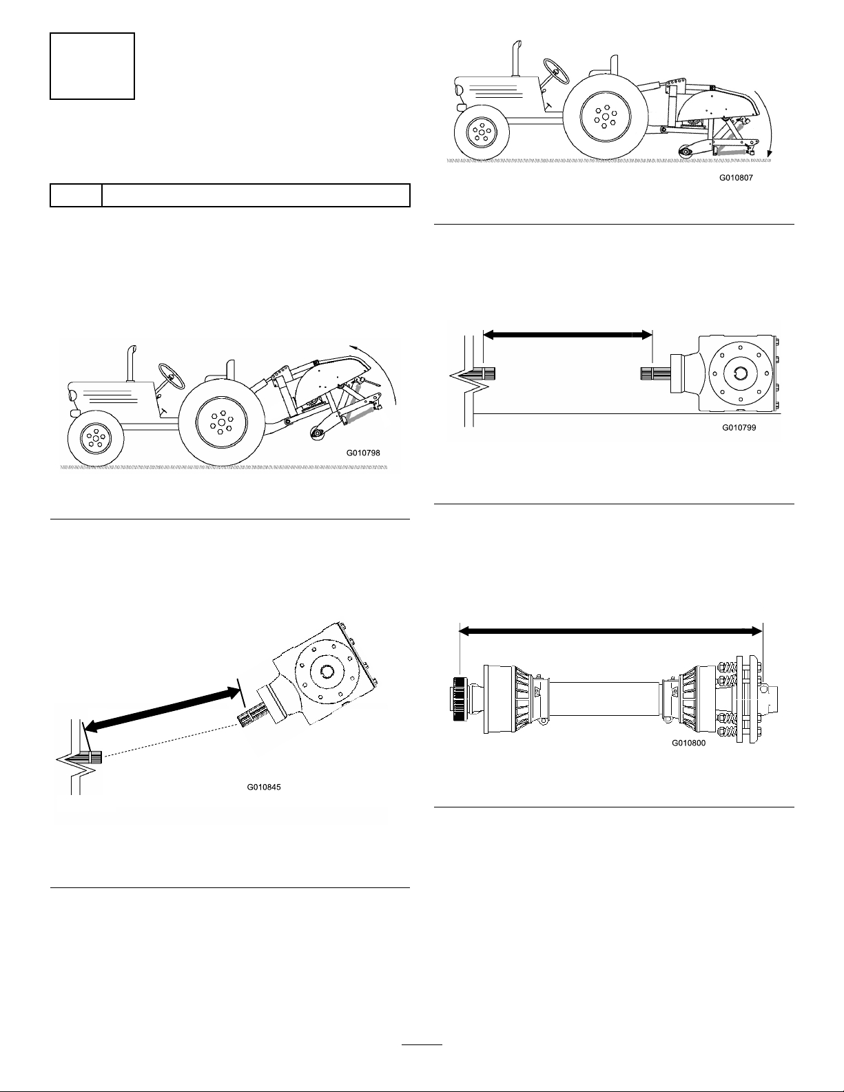
3.Measurethedistancefromthelockinggrooveonthe
endofthetractorPTOshafttothelockinggroove
ontheaeratorgearboxPTOshaft(Figure12).
Recordthisdistance.Example:26.5inches(67cm).
Figure12
1.Measurehere2.Lockinggroove
4.Lowertheaeratortothegroundandfullyextendthe
hydraulictoplinkcylinderorupperlink(Figure13).
Figure13
5.Measurethedistancefromthelockinggrooveonthe
endofthetractorPTOshafttothelockinggroove
ontheaeratorgearboxPTOshaft(Figure14).
Recordthisdistance.Example:27.5inches(70cm).
Figure14
1.Measurehere2.Lockinggroove
6.OnthePTOshaft,measurethedistancefromthe
centeroflockingpinballononeendtothecenterof
thelockingpinontheotherend(Figure15).Record
thisdistance.Example:32inches(81cm).
Figure15
1.Measurehere
7.Usingthesmallerofthetwomeasurementsin
Figure14andFigure12,subtractthatdistancefrom
thedistanceinFigure15.Example32(81cm)inches
minus26.5inches(67cm)equals5.5inches(14cm).
8.Theexamplemeasurementsshowthattheshaftis
5.5inchestoolong.Addanextra1/2inch(1.2cm)
tobesurethatthePTOshaftwillnotbottomout
whentheaeratorisliftedtoitshighestposition.
Example:5.50inches(14cm)plus1/2inch(1.2cm)
equals6.00inches(15cm).
14

9.SlidethePTOshafttubestogetheruntiltheyare
fullycollapsed.Verifythattheinsidetubedoesnot
protrudeintothecrossandbearingsectionofthe
outertube(Figure16).Ifthishappens,morewill
havetobecutofftheinsidetube,tocorrectthe
problem.Proceedtonextstep.
10.Measurethedistancetheinsidetubeprotrudesinto
thecrossandbearingsectionoftheoutertube
(Figure16).Addthisdistancetothedimension
attainedinstep8.
Figure16
1.Cutoff2.Insidetube
11.SeparatethetwohalvesofthePTOshaft(Figure17,
illustration1).
12.Measurethedistancefromtheendofeachtubeto
itssafetyshield(Figure17,illustration1).Record
thedistances.
13.Usingthedimensionsdeterminedinstep8,locate,
markandcutofftheshieldandtubefromeachPTO
half(Figure17,illustrations2&3).
Note:Morewillhavetobecutofftheinsidetubeif
itwasprotrudingintothecrossandbearingsection
oftheoutertube.
14.Usingthedimensionsdeterminedinstep11,locate,
markandcutoffjustthesafetyshieldstoexposethe
tubesFigure17,illustrations4&5.
15.Carefullydeburrtheendsofthetubeswithaleand
removeallthelingsfromthetubes.
16.Greasetheinsidetube.
Note:Telescopingtubesmustalwaysoverlapby
1/2oftheirlengthinnormaloperationandatleast
1/3oftheirlengthinallworkingconditions.During
transport,whenthedrivelineisnotrotating,the
telescopingtubesmusthaveasuitableoverlapto
maintainthetubesalignmentandallowthemtoslide
freely.
Figure17
1.Measurehere
8
InstallingthePTOShield
Partsneededforthisprocedure:
1PTOShield
Procedure
1.Removethe4bolts,lockwashersandatwashers
securedtotherearoftheaeratorgearbox(Figure18).
15

Figure18
1.PTOshield4.Bolt
2.Flatwasher5.Accesspanel
3.Lockwasher
2.MountthePTOshieldtotheaeratorgearboxwith
thefastenerspreviouslyremoved(Figure18).When
mountingthePTOshield,makesuretheaccess
panel(Figure18)ispositionedtothetoporside
dependingontheaeratorframeconguration.
9
ConnectingthePTOShaft
Partsneededforthisprocedure:
1Pin(suppliedwithPTOshaft)
1Nut(suppliedwithPTOshaft)
Procedure
Note:Theaccesspanel(Figure18)canbeopened
toeasetheremovalandinstallationofthePTOshaft
mountingfasteners.
1.RemovethepinandnutfromthePTOshaft
(Figure19).
2.ConnecttheclutchendofthePTOshafttothe
aeratorgearboxinputshaftwithpinandnut
previouslyremoved(Figure19).Thepincanonly
beinsertedoneway.
Figure19
1.Gearboxinputshaft3.Pin
2.PTOshaftcoupler4.Nut
Note:MakesuretocloseandlatchthePTOshield
accesspanelifopened.
Note:Makesurethepinisfullyinsertedintothe
yokeofthePTO.
3.ConnectthePTOshafttothetractorPTOshaft
(Figure20).
Figure20
1.Tractoroutputshaft3.PTOshaft
2.PTOshaftcoupler
4.SlidethePTOshaftforwardasfarasthetractor
allows.
5.PullbackonthelockingcollartosecurethePTO
shaftinplace.SlidethePTOshaftbackandforthto
makesureitisproperlylocked.
6.ConnecttheshieldsafetychainstothePTOshield
andthetractorbracket(Figure21).Makesurethe
chainsremainslackwhentheaeratorisraisedor
lowered.
16

Figure21
1.Safetychains
Note:Toavoidexcesslift,connecttheliftarmsof
thetractorintothetopholesoftheliftbracket,if
soequipped(Figure22).Themaximumangleon
thePTOshaftis35º.
Figure22
1.Topholes
Important:WhenconnectingthePTO,be
surethattheaeratorisnotbeingliftedhigher
thanisnecessary.Liftingthemachinetoohigh
willcausethePTOshaftknucklestobreak
(Figure23).NeverleavethePTOturningwhen
theaeratorislifted.ThePTOcanbeoperated
uptoanangleof25º,butcanneverexceeda35º
anglewhentheaeratorisatitshighestposition.
7.VerifythatthePTOshielddoesnotinterferewith
theclutch.
Figure23
1.Breakagewilloccurhere
10
AdjustingtheSwayLinks
NoPartsRequired
Procedure
Theaeratorisdesignedtobecenteredwiththetractor
PTOshaftcenterline.Adjusttheswaylinksasrequired.
ThePTOshaftshouldbeasstraightaspossibletothe
tractorPTOshaft.
Adjusttheswaylinksonthelowerliftarmstominimize
side-to-sideswaytoamaximumof1inch(25mm)on
eachside(Figure24).
Figure24
1.Swaylink
17

Adjustthelowerlinksinboarduntiltheycontactthe
aeratormountingplates.Thiswillreducethestress
onthepins.Ifthetractorhasswaychainsinsteadof
swaylinks,itisrecommendedthatwashersbeinstalled
betweenthelowerlinkarmandlynchpintoreducethe
overhungloadontheliftpins.
Note:RefertothetractorOperator'sManualfor
additionalinstallationandadjustmentprocedures.
11
LevelingtheAerator
Side-to-Side
Partsneededforthisprocedure:
1Level(notsupplied)
Procedure
1.Parkthetractorandaeratoronalevel,rmsurface.
2.Placealevelontopoftheaeratorframetocheckfor
levelside-to-side(Figure25).
Figure25
1.Level
3.Turntheadjustablelinkbody(ifprovided)toraise
orlowerthelinkarmuntiltheaeratorisleveled
side-to-side.
Note:RefertotractorOperator'sManualfor
additionaladjustmentprocedures.
12
InstallingtheTines
Partsneededforthisprocedure:
A/RTines
Procedure
Awideselectionoftinesareavailablefortheaerator.
Choosethetinetype,sizeandspacingsrequiredforthe
job.RefertothePartsCatalogforthelistofaccessories.
1.Makecertaintheaeratorisfullysupportedonthe
standsorsupportblocks.
2.Turnoffthetractorengineandremovethekey.
3.Loosentheclampingboltsandremovethepreviously
usedtines(Figure26).
Figure26
1.Tine2.Clampingbolt
4.Slidethenewtinesintotheholessizedtotthetines
selected.Neverusesmalldiametertinesinthelarge
diameterholes-thetinesshouldtcloselyinthe
hole.Besuretoslidethetineupintotheheaduntil
itbottomsout.
Note:Hollowcoringtinesshouldbepositioned
withtheejectionslottotherearwhilethesolidtines
shouldhavethetinetipanglefacingthemachine
(Figure26).
5.Tightentheclampingboltsrmlytosecurethetines.
6.Setthetineangleforthenewtines.Referto
AdjustingtheTineAngleintheOperationsection.
7.Beforeaeratingformalturfforthersttimeafter
installingtines,testtheaeratoronalessimportant
areasothatyoucantryalternativetractorgearsand
netunetheadjustmenttoachievetheholespacing
andturfappearancedesired.
18

13
SettingtheTineDepth
(ModelsSR54–SandSR70–S)
NoPartsRequired
Procedure
Thetinedepthcanbechangedbyraisingorloweringthe
rearroller.Therollerheightisadjustedbymovingthe
rolleradjustingboltstothedesiredposition.
Note:TheaeratorisshippedinPositionA.
Figure27
•PositionA-Maximumdepth
•PositionB-Depthisdecreased1–1/2inchesfrom
PositionA
•PositionC-Depthisdecreased3inchesfrom
PositionA
14
InstallingtheRearGuard
Partsneededforthisprocedure:
1Rearguard
4Screw,3/8x3–1/4inch
12Flatwasher,.438x1.00inch
4Locknut
2Endcap
Procedure
1.Inserttheendcapsintotheendsoftherearguard
tubes(Figure28).
Figure28
1.Rearguard3.Uppermountinghole
2.Endcap4.Lowermountinghole
2.Aligntheholesintherearguardmountingtubes
withtheholesintheaeratorsideplates(Figure28).
Note:OnSR54–SandSR70–Smodels,mountthe
endsofthetubestothelowersideplatemounting
holesiftheaeratortinedepthissetinPositionA
(Figure29).Usetheuppermountingholesfordepth
settingPositionsBorC.
19

Figure29
3.Securetheguardmountingtubestothesideplates
with(4)screws,atwashersandnuts(Figure28).
Note:Usetheremainingwashers,asrequired,toll
anygapbetweenthetubesandtheaeratorsideplates.
15
InstallingtheLatchLock
Partsneededforthisprocedure:
2Lockplate
2Tapbolt
2Retainingring
Procedure
1.Positionthelatchplateoverthehoodlatchwhile
aligningthemountingholewiththeholeintheside
plate(Figure30).
Figure30
1.Retainingring3.Latchplate
2.Mountinghole4.Tapbolt
2.Securethelatchplatetothesideplatewithatapbolt
andaretainingring(Figure30).
3.Repeattheprocedureontheotherhoodlatch.
16
RemovingtheStorageStands
(ModelsSR54andSR70)
NoPartsRequired
Procedure
1.Raisetheaeratorroller(s)3-6inchesoffground.
Placesupportblocksundertheroller(s).
2.Removethebolts,lockwashersandnutssecuringthe
storagestandstoeachendoftheaerator(Figure31).
20
This manual suits for next models
13
Table of contents
Other Toro Tiller manuals


