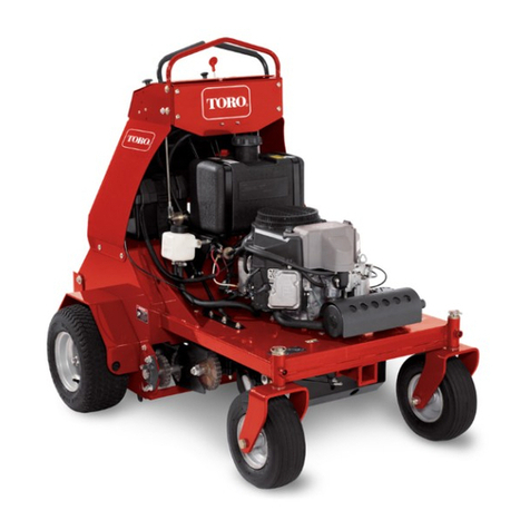
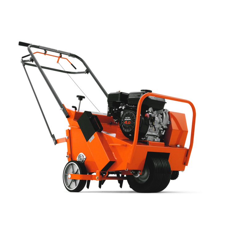
Toro 09802 HydroJect 3010 User manual

FormNo.3360-899RevB
HydroJect®3010Aerator
ModelNo.09802—SerialNo.280000001andUp
ToregisteryourproductordownloadanOperator'sManualorPartsCatalogatnocharge,gotowww.Toro.com.OriginalInstructions(EN)

Introduction
Important:Theengineinthisproductisnot
equippedwithasparkarrestermufer.Itisa
violationofCaliforniaPublicResourceCode
Section4442touseoroperatethisengineonany
forest-covered,brush-covered,orgrass-covered
landasdenedinCPRC4126.Otherstatesor
federalareasmayhavesimilarlaws.
Readthisinformationcarefullytolearnhowtooperate
andmaintainyourproductproperlyandtoavoidinjury
andproductdamage.Youareresponsibleforoperating
theproductproperlyandsafely.
YoumaycontactTorodirectlyatwww.Toro.comfor
productandaccessoryinformation,helpndinga
dealer,ortoregisteryourproduct.
Wheneveryouneedservice,genuineToroparts,or
additionalinformation,contactanAuthorizedService
DealerorToroCustomerServiceandhavethemodel
andserialnumbersofyourproductready.Themodel
andserialnumbersareonaplateontheproduct.Write
thenumbersinthespaceprovided.
ModelNo.
SerialNo.
Thismanualidentiespotentialhazardsandhas
safetymessagesidentiedbythesafetyalertsymbol
(Figure1),whichsignalsahazardthatmaycauseserious
injuryordeathifyoudonotfollowtherecommended
precautions.
Figure1
1.Safetyalertsymbol
Thismanualuses2otherwordstohighlightinformation.
Importantcallsattentiontospecialmechanical
informationandNoteemphasizesgeneralinformation
worthyofspecialattention.
Warning
CALIFORNIA
Proposition65Warning
Theengineexhaustfromthisproduct
containschemicalsknowntotheStateof
Californiatocausecancer,birthdefects,
orotherreproductiveharm.
ThissparkignitionsystemcomplieswithCanadian
ICES-002.
©2008—TheToro®Company
8111LyndaleAvenueSouth
Bloomington,MN554202
Contactusatwww.Toro.com.
PrintedintheUSA.
AllRightsReserved

Contents
Introduction.................................................................2
Safety...........................................................................4
SafeOperatingPractices.......................................4
SafetyandInstructionalDecals.............................6
Setup............................................................................9
1InstallingtheRearWheels..................................9
2ActivatingandChargingtheBattery....................9
3CheckingtheTirePressure...............................11
ProductOverview......................................................12
Controls.............................................................12
Specications.....................................................13
Attachments/Accessories...................................13
DepthsandNozzleCongurations.....................14
..........................................................................14
Operation...................................................................15
ThinkSafetyFirst...............................................15
CheckingtheEngineOil.....................................15
FillingtheGasTank...........................................15
CheckingtheGearCaseFluidLevel....................16
CheckingthePumpCaseOilLevel......................17
WaterSystemAccumulator.................................18
OperatingPrecautions........................................18
StartingandStoppingtheEngine........................18
TrainingPeriod...................................................18
WaterSupply......................................................19
OperatingProcedure..........................................19
CheckingtheInterlockSystem............................20
TransportOperation..........................................21
InspectionandClean-UpAfterUse.....................21
PushingorTowingtheMachine..........................21
Maintenance...............................................................23
RecommendedMaintenanceSchedule(s)................23
WaterSystemAccumulator.................................23
DailyMaintenanceChecklist...............................24
LubricatingtheMachine.....................................25
ServicingthePre-Filter.......................................26
ReplacingtheMainWaterFilter..........................26
ChangingtheEngineOilandFilter.....................27
GeneralAirCleanerMaintenance.......................27
ServicingtheAirCleaner....................................27
CheckingandReplacingtheSparkPlugs..............28
ChangingtheGearCaseOilandFilter.................29
ChangingthePumpCaseOil..............................30
CheckingtheHydraulicLinesandHoses.............30
AdjustingtheTractionPumpBelt.......................30
AdjustingtheTransmissionforNeutral...............31
AdjustingtheAerationSpeed..............................32
AdjustingtheParkingBrake................................32
AdjustingtheRollerSprayWashSystem..............33
ServicingtheSprayWashNozzlesor
Strainers.........................................................33
CaringfortheBattery.........................................33
Storage.......................................................................34
PreparingtheWaterSystem................................34
PreparingtheEngine..........................................34
PreparingtheTractionUnit................................34
Troubleshooting.........................................................35
Schematics.................................................................38
3

Safety
Improperuseormaintenancebytheoperatoror
ownercanresultininjury.Toreducethepotential
forinjury,complywiththesesafetyinstructions
andalwayspayattentiontothesafetyalert
symbol,whichmeansCAUTION,WARNING,or
DANGER-"personalsafetyinstruction."Failureto
complywiththeinstructionmayresultinpersonal
injuryordeath.
SafeOperatingPractices
ThefollowinginstructionsarefromANSIstandard
B71.4-2004.
Training
•ReadtheOperator’sManualandothertraining
material.Iftheoperator(s)ormechanic(s)cannot
readEnglishitistheowner’sresponsibilitytoexplain
thismaterialtothem.
•Becomefamiliarwiththesafeoperationofthe
equipment,operatorcontrols,andsafetysigns.
•Alloperatorsandmechanicsshouldbetrained.The
ownerisresponsiblefortrainingtheusers.
•Neverletchildrenoruntrainedpeopleoperateor
servicetheequipment.Localregulationsmayrestrict
theageoftheoperator.
•Theowner/usercanpreventandisresponsiblefor
accidentsorinjuriesoccurringtohimselforherself,
otherpeopleorproperty.
Preparation
•Evaluatetheterraintodeterminewhataccessories
andattachmentsareneededtoproperlyand
safelyperformthejob.Onlyuseaccessoriesand
attachmentsapprovedbythemanufacturer.
•Wearappropriateclothingincludinghardhat,safety
glassesandhearingprotection.Longhair,loose
clothingorjewelrymaygettangledinmovingparts.
•Inspecttheareawheretheequipmentistobeused
andremoveallobjectssuchasrocks,toysandwire
whichcanbecontactedbytheaerator.
•Useextracarewhenhandlinggasolineandother
fuels.Theyareammableandvaporsareexplosive.
–Useonlyanapprovedcontainer.
–Neverremovegascaporaddfuelwithengine
running.Allowenginetocoolbeforerefueling.
Donotsmoke.
–Neverrefuelordraintheaeratorindoors.
•Checkthattheoperatorpresencecontrols,safety
switchesandshieldsareattachedandfunctioning
properly.Donotoperateunlesstheyarefunctioning
properly.
Operation
•Onlyoperateingoodlight,keepingawayfromholes
andhiddenhazards.
•Besurealldrivesareinneutralandparkingbrakeis
engagedbeforestartingengine.Starttheengineonly
fromtheoperatorsposition.
•Neveroperatewithouttheshields,coversorother
guardssecurelyinplace.Besureallinterlocksare
functioningproperly.
•Keephandsandfeetawayfromthenozzleand
rollerarea.Highvelocitywaterjetscanpenetrate
handsandfeet.Penetrationbythehighvelocity
waterjetscancauseseriouspersonalinjury.If
accidentalpenetrationoccurs,seekmedicalattention
immediately.
•Neverusechemicalsinthewatersupplysystem.
•Donotoperatethewaterinjectionsystem
onconcreteorasphaltbecausewaterjetswill
permanentlydamagethesesurfaces.
•Beforedisconnectingorperforminganyworkon
thewatersystem,allpressureinthesystemmust
berelievedbystoppingtheengineandopeningthe
bleedvalve.Openingthebleedvalveallowsany
trappedwatertoescapefromthesystemandalso
allowstheaccumulatorpistontomovetothebottom
oftheaccumulatorcylinder.
•Donotchangetheenginegovernorsettingor
overspeedtheengine.
•Theaccumulatorinthismachinecontainshigh
pressuredrynitrogen.Accumulatorservicing
requiresspecialtoolsandprecautions.Accumulators
donotcontainuserserviceablecomponents.
Improperaccumulatorservicingcancause
dismembermentordeath.Donotattemptto
disassembleanaccumulator;havethisworkdoneby
anAuthorizedToroDistributor.
•Stoponlevelground,disengagedrives,engage
parkingbrake,shutoffenginebeforeleavingthe
operator’spositionforanyreason.
•Nevercarrypassengersandkeeppetsandbystanders
away.
•Bealert,slowdownandusecautionwhenmaking
turns.Lookbehindandtothesidebeforechanging
directions.
4

•Slowdownandusecautionwhencrossingroads
andsidewalks.
•Donotoperatetheaeratorundertheinuenceof
alcoholordrugs.
•Useextremecarewhenloadingorunloadingthe
aeratorintoatrailerortruck.
•Usecarewhenapproachingblindcorners,shrubs,
trees,orotherobjectsthatmayobscurevision.
•Alwaysbeawareofobstaclesthatmaybeinthe
areaofoperation.Planyouraerationpathtoavoid
contactwithanyobstaclebyyouorthemachine.
SlopeOperation
•Donotoperateneardrop-offs,ditches,steepbanks
orwater.Wheelsorrollersdroppingoveredgescan
causerollovers,whichmayresultinseriousinjury
ordeath.
•Donotoperateonslopeswhengrassiswet.Slippery
conditionsreducetractionandcouldcausesliding
andlossofcontrol.
•Donotmakesuddenturnsorrapidspeedchanges.
•Reducespeedanduseextremecautiononslopes.
•Removeormarkobstaclessuchasrocks,treelimbs,
etc.fromtheoperatingarea.Tallgrasscanhide
obstacles.
•Watchforditches,holes,rocks,dips,andrisesthat
changetheoperatingangle,asroughterraincould
overturntheaerator.
•Beawarethatlossoftractionmayoccurgoing
downhill.Weighttransfermaycausedrivewheelto
slipandcauselossofbrakingandsteering.
•Beawarethatlossoftractionmayoccurgoing
downhill.Weighttransfermaycausedrivewheelto
slipandcauselossofbrakingandsteering.
•Alwaysavoidsuddenstartingorstoppingonaslope.
Iftirelosestraction,disengagethewaterinjection
systemandproceedslowlyofftheslope.
MaintenanceandStorage
Engineexhaustcontainscarbonmonoxide,
whichisanodorless,deadlypoisonthatcan
killyou.
Donotrunengineindoorsorinanenclosed
area.
•Makesureallhydrauliclineconnectorsaretightand
allhydraulichosesandlinesareingoodcondition
beforeapplyingpressuretothesystem.
•Keepyourbodyandhandsawayfrompinhole
leaksornozzlesthatejecthydraulicuidunder
highpressure.Usepaperorcardboard,notyour
hands,tosearchforleaks.Hydraulicuidescaping
underpressurecanhavesufcientforcetopenetrate
theskinandcauseseriousinjury.Seekimmediate
medicalattentionifuidisinjectedintoskin.
•Beforedisconnectingorperforminganyworkon
thewatersystem,allpressureinthesystemmust
berelievedbystoppingtheengineandopeningthe
bleedvalve.Openingthebleedvalveallowsany
trappedwatertoescapefromthesystemandalso
allowstheaccumulatorpistontomovetothebottom
oftheaccumulatorcylinder.
•Letenginecoolbeforestoringanddonotstorenear
ame.
•Shutofffuelwhilestoringortransportingontrailers.
Donotstorefuelnearamesordrainindoors.
•Parkmachineonlevel,hardground.Neverallow
untrainedpersonneltoservicemachine.
•Usejackstandsorsafetylatchestosupport
componentswhenrequired.
•Carefullyreleasepressurefromcomponentswith
storedenergy.
•Disconnectbatteryorremovesparkplugwirebefore
makinganyrepairs.Disconnectthenegativeterminal
rstandthepositivelast.Reconnectpositiverst
andnegativelast.
•Keephandsandfeetawayfrommovingparts.If
possible,donotmakeadjustmentswiththeengine
running.
•Chargebatteriesinanopenwellventilatedarea,
awayfromsparkandames.Unplugchargerbefore
connectingordisconnectingfrombattery.Wear
protectiveclothinganduseinsulatedtools.
•Keepallpartsingoodworkingconditionandall
hardwaretightened.Replaceallwornordamaged
decals.
•UseonlyToro-approvedattachments.Warrantymay
bevoidedifusedwithunapprovedattachments.
5

SoundPressureLevel
ThisunithasanequivalentcontinuousA-weighted
soundpressurelevelattheoperatorearof93dBA,based
onmeasurementsofidenticalmachinesperDirective
98/37/ECandamendments.
SoundPowerLevel
Thisunithasaguaranteedsoundpowerlevelof:
108dBA/1pW ,basedonmeasurementsofidentical
machinesperDirective2000/14/ECandamendments.
VibrationLevel
Thisunitdoesnotexceedavibrationlevelof4.0m/s2at
thehandsbasedonmeasurementsofidenticalmachines
perISO5349procedures.
SafetyandInstructionalDecals
Safetydecalsandinstructionsareeasilyvisibletotheoperatorandarelocatednearanyareaof
potentialdanger.Replaceanydecalthatisdamagedorlost.
80-8000
80-8880
80-8760
93-9363
1.Parkingbrake3.Unlocked
2.Locked
80-8090
80-8040
6

92-9542
72-4080
93-9429
108-1316
80-8010
108-1317
7

108-1263
1.Choke
80-9450
108-1264
108-1265
8

Setup
LooseParts
Usethechartbelowtoverifythatallpartshavebeenshipped.
ProcedureDescriptionQty.Use
Wheel3
1Lugnut12Installtherearwheels
2Bulkelectrolyte,notsuppliedA/RActivateandchargethebattery.
3Nopartsrequired–Checkthetirepressure.
MediaandAdditionalParts
DescriptionQty.Use
IgnitionKey1Useinignitionswitch.
HoseAdapter1Mounttoquickcoupleronsideofmachine.
SpannerWrench1Useforinstallationandremovalofwaterlter.
Operator’sManual1Readbeforeoperatingtheaerator
PartsCatalog1Usetoreferencepartnumbers.
1
InstallingtheRearWheels
Partsneededforthisprocedure:
3Wheel
12Lugnut
Procedure
1.Removethewheelsfromtheshippingpallet.
2.Mountthewheelstothehubswiththelugnuts
(suppliedinlooseparts)(Figure2)andtorquethe
nutsto45-55ft./lb.(61-75N-m).
Figure2
1.Wheel2.Lugnuts
3.Removeanyshippingblocksorbraces,whichmay
obstructmachineremovalfromthepallet.
9

2
ActivatingandChargingthe
Battery
Partsneededforthisprocedure:
A/RBulkelectrolyte,notsupplied
Procedure
Warning
CALIFORNIA
Proposition65Warning
Batteryposts,terminals,andrelated
accessoriescontainleadandleadcompounds,
chemicalsknowntotheStateofCalifornia
tocausecancerandreproductiveharm.
Washhandsafterhandling.
1.Sincethebatteryisnotlledwithelectrolyteor
activated,bulkelectrolytewith1.265specicgravity
mustbepurchasedfromalocalbatterysupplyoutlet
Warning
CALIFORNIA
Proposition65Warning
Batteryelectrolytecontainssulfuricacidwhich
isadeadlypoisonandcausessevereburns.
•Donotdrinkelectrolyteandavoidcontact
withskin,eyesorclothing.Wearsafety
glassestoshieldyoureyesandrubber
glovestoprotectyourhands.
•Fillthebatterywherecleanwaterisalways
availableforushingtheskin.
2.Releasethehoodlatchesandraisethehood.
Important:Donotaddelectrolytewhilethe
batteryisinthemachine.Youcouldspillit,
causingcorrosion.
3.Loosenthecapscrewsecuringthebatteryclampto
themachineandremovethebattery(Figure3).
Warning
CALIFORNIA
Proposition65Warning
Batteryterminalsormetaltoolscouldshort
againstmetaltractorcomponentscausing
sparks.Sparkscancausethebatterygasses
toexplode,resultinginpersonalinjury.
•Whenremovingorinstallingthebattery,
donotallowthebatteryterminalstotouch
anymetalpartsofthetractor.
•Donotallowmetaltoolstoshort
betweenthebatteryterminalsand
metalpartsofthetractor.
Figure3
1.Battery
4.Cleanthetopofthebatteryandremovethevent
caps.
5.Carefullylleachcellwithelectrolyteuntiltheplates
arecoveredwithabout1/4inch(6mm)ofuid.
6.Allowapproximately20to30minutesforthe
electrolytetosoakintotheplates.Rellasnecessary
tobringtheelectrolytetowithinabout1/4inch(6
mm)ofthebottomofthellwell.
Chargingthebatteryproducesgassesthatcan
explode.
Neversmokenearthebatteryandkeepsparks
andamesawayfrombattery.
7.Connecta3to4ampbatterychargertothebattery
posts.Chargethebatteryatarateof3to4amps
10

untilthespecicgravityis1.250orhigherandthe
temperatureisatleast60degreesF(16degreesC)
withallcellsgassingfreely.
8.Whenthebatteryischarged,disconnectthecharger
fromtheelectricaloutletandbatteryposts.
Note:Afterthebatteryhasbeenactivated,add
onlydistilledwatertoreplacenormalloss,although
maintenance–freebatteriesshouldnotrequirewater
undernormaloperatingconditions.
9.Installthebatteryandsecureitwiththebattery
clamp.
10.First,installthepositivecable(red)tothepositive
(+)terminalandthenthenegativecable(black)to
thenegative(–)terminalofthebattery.Slidethe
rubberbootoverthepositiveterminaltopreventa
possibleshortfromoccurring.
Warning
CALIFORNIA
Proposition65Warning
Incorrectbatterycableroutingcoulddamage
themachineandcablescausingsparks.Sparks
cancausethebatterygassestoexplode,
resultinginpersonalinjury.
•Alwaysdisconnectthenegative(black)
batterycablebeforedisconnectingthe
positive(red)cable.
•Alwaysconnectthepositive(red)
batterycablebeforeconnectingthe
negative(black)cable.
Warning
CALIFORNIA
Proposition65Warning
Connectingcablestothewrongpost
coulddamagetheelectricalsystemand
resultinpersonalinjury.
Note:Makesurebatterycablesareroutedaway
fromanysharpedgesormovingparts.
11.Lowerthehoodandsecurethelatches.
3
CheckingtheTirePressure
NoPartsRequired
Procedure
Thetiresareover–inatedforshipping.Therefore,
releasesomeoftheairtoreducethepressure.Correct
airpressureinfrontandreartiresis8–12psi.
11

ProductOverview
Controls
IgnitionSwitch
Theignitionswitch(Figure4),whichisusedtostart
andstoptheengine,hasthreepositions:OFF,ON,and
START.
Figure4
1.Ignitionswitch6.Waterpressuregauge
2.Choke7.Circuitbreakerreset
button
3.Throttle8.Spacingcontrollever
4.Spraywashcontrol9.Accumulatorpressure
lights
5.Hourmeter
Choke
Tostarttheengine,closethecarburetorchokebypulling
thechokecontrol(Figure4)outwardtotheFULL
position.Aftertheenginestarts,regulatethechoketo
keeptheenginerunningsmoothly.Assoonaspossible,
openthechokebypushingitinwardtotheOFFposition
Throttle
Thethrottle(Figure4)isusedtoregulatetheengine
speed.Movingthethrottleforwardincreasestheengine
speed(FAST);rearwarddecreasestheenginespeed
(SLOW).
SprayWashControl
Pullthehandle(Figure4)upwardtoactivatetheroller
spraywashsystem.Movethecontrolknobupordown
toadjustthesprayratetokeeptherollersfreeofdebris.
HourMeter
Thehourmeter(Figure4)registersaccumulatedhours
ofengineoperation.Usethehourmetertodetermine
intervalsforservicemaintenanceandlubrication.
WaterPressureGauge
Thewaterpressuregauge(Figure4)registerssupply
waterpressureinthesystem.Italsoactsasaninterlock
switch,preventingthewaterpumpfromstartingifthe
waterpressureisbelow20-28p.s.i.,orstoppingthewater
pumpifthewaterpressuredropsbelow7-13p.s.i.Check
thegaugefrequentlytomonitorthewaterpressure.
CircuitBreakerResetButton
Pushthebutton(Figure4)toresetthebreakerafter
correctingamalfunctionintheelectricalsystem.The
buttonalsoservesasaswitchtointerruptpowertothe
relays.
SpacingControlLever
Movingthecontrol(Figure4)awayfromthehandle
increasestheaeratinggroundspeedandthedistance
betweenholes.Movingthecontroltowardthehandle
decreasestheaeratinggroundspeedandthedistance
betweenholes.Thesettingwillbeoverriddenwhenthe
machineisshiftedtothetransportposition.
AccumulatorPressureLights
Thehighorlowpressurelights(Figure4)willonly
illuminateifahighorlowpressureconditionoccurs
intheaccumulator.Ifalightilluminatesthesystem
willlnotoperateorwillshutdown,ifoperating.Refer
toWaterSystemAccumulatorinformationinthe
Operationsection.
TractionBail
Thetractionbail(Figure5)engagesandregulatesfore
andafttractionoperationofthemachine.Releasingthe
bailstopstractionoperationandwillalsostopwater
injectionin3to4seconds,unlessthebailisre-engaged.
Thetransportspeedisregulatedbytheamountthebail
ismoved.
12

Figure5
1.Tractionbail4.Aerationstopbutton
2.Transport/aeraterocker
switch
5.Parkingbrake
3.Aerationengagement
button
Transport/AerateRockerSwitch
Theswitch(Figure5)lowersmachineontotherollers
tocommenceaeration.Theswitchwilloverridethe
spacingcontrolsettingwhenitismovedtothetransport
position.
AerationEngagementButton
Depressingthebutton(Figure5),startsthewater
injectionsystemonlywhenthewaterpressureisabove
28p.s.i.andtherollersareontheground.
AerationStopButton
Theredbutton(Figure5)stopsthewaterinjection
system.Thesystemcontinuesforafewsecondsafter
thebuttonispressed.
ParkingBrake
Pushthelever(Figure5)towardthemachinetoengage
theparkingbrake.Awarningbuzzerwillsoundif
youattempttomovethemachinewithparkingbrake
engaged.
FuelShut-OffValve
Thefuelshut-offvalveislocatedunderthefueltank.
Closethevalvewhenstoringortransporting(trailering)
themachine.
Specications
Note:Specicationsanddesignaresubjecttochange
withoutnotice.
Length96.2inches(244cm)
Wheelbase53.2inches(135cm)
Width63inches(160cm)
Height38.2inches(97cm
Weight1120lb.(508kg)
Attachments/Accessories
AselectionofToroapprovedattachmentsand
accessoriesareavailableforusewiththemachineto
enhanceandexpanditscapabilities.Contactyour
AuthorizedServiceDealerorDistributororgoto
www.Toro.comforalistofallapprovedattachments
andaccessories.
13

DepthsandNozzleCongurations
Allnozzlesareidentiedwithnumbersindicatingthedrillsizeoftheorice.Thestandardcongurationis11
nozzlesproducingdepthsof4to6inchesdependingonturfconditions.Blockednozzlelocationsareobtainedby
reversingthenozzlecheckvalveballandspring.Seenozzlesizechartandillustrationsbelow:
Important:Useonlynozzlecongurationsshownordamagetothemachinemayoccur.
NozzleSizeandApproximateDepthChart
QuantityofNozzles
PartNo.DrillSizeDecimalSize
(inch)
MetricSize
(mm)OpenBlocked
Approximate.
Depth
86-8130#560.04651.181***
86-8131#530.05951.5111104-6inches
86-8133#460.0812.057656-8inches
*Useonlywithvariedsizecongurations
Important:AluminumWasher,ToroPartno.80-6680,isrequiredwithanynozzlechange.
OptionalStaggeredSizeNozzleConguration
QuantityofNozzles
PartNo.DrillSizeDecimalSize
(inch)
MetricSize
(mm)OpenBlocked**
Approximate.
Depth
86-8130#560.04651.1816and0**3-4inches
86-8133#460.0812.05750**6-8inches
**Additionalnozzlesmaybeblockedtocompensateforpumpwear.
Important:AluminumWasher,ToroPartno.80-6680,isrequiredwithanynozzlechange.
Figure6
OpenNozzle
1.Checkvalveball2.Spring
Figure7
Closed(Blocked)Nozzle
1.Spring2.Checkvalveball
14

Operation
Note:Determinetheleftandrightsidesofthe
machinefromthenormaloperatingposition.
ThinkSafetyFirst
Pleasecarefullyreadallofthesafetyinstructions
andsymbolsinthesafetysection.Knowingthis
informationcouldhelpyouorbystandersavoidinjury.
Theuseofprotectiveequipment,suchasbutnot
limitedto,foreyes,ears,feet,andheadisrecommended.
Thismachineproducessoundlevelsinexcess
of85dBAattheoperatorsearandcancause
hearinglossthroughextendedperiodsof
exposure.
Wearhearingprotectionwhenoperatingthis
machine.
CheckingtheEngineOil
ServiceInterval:Beforeeachuseordaily—Checkthe
engineoil.
Theengineisshippedwithoilinthecrankcase;
however,theoillevelmustbecheckedbeforeandafter
theengineisrststarted.
Crankcasecapacityisapproximately2qt(1.4l)with
thelter.
Usehigh-qualityengineoilthatmeetsthefollowing
specications:
APIClassicationLevelRequired:SJ,SK,SLorhigher.
Preferredoil:SAE10W–30(above0degreesF)
Alternateoil:SAE5W–30(below32degreesF)
ToroPremiumEngineoilisavailablefromyour
distributorin10W–30viscosity.Seethepartscatalog
forpartnumbers.
1.Parkthemachineonalevelsurface,stoptheengine
andremovethekeyfromtheignitionswitch.
2.Removethedipstickfromtheoilllerneck
(Figure8)andwipeitwithacleanrag.Insertthe
dipstickintothellerneckandmakesureitisseated
fully.Pullthedipstickfromthellerneckandcheck
theoillevel.Iftheoillevelislow,addenoughoilto
raisetheleveltotheFULLmarkonthedipstick
Figure8
1.Dipstick
2.Oilllcap
Note:IftheoillevelisattheADDmarkonthe
dipstick,add1quartofoiltoraisetheoillevelto
FULL.Donotoverll.
3.Removethecapfromtheoilll.Pouroilintothe
oillluntilthelevelisattheFULLmarkonthe
dipstick.
Important:Theaeratoroperatesatvery
highengineloads,sochecktheoillevelevery
8operatinghoursordaily.Anewengine
mayconsumesomeoiluntilitisbrokenin.
Initially,changetheoilaftertherst25hoursof
operation;thereafter,undernormalconditions,
changetheoilandlterafterevery100hours
ofoperation.Changetheoilmorefrequently
whentheengineisoperatedinextremelydusty
ordirtyconditions.
FillingtheGasTank
Werecommendtheuseoffresh,clean,unleadedregular
gradegasoline.Unleadedgasolineburnscleaner,
extendsenginelife,andpromotesgoodstartingby
reducingthebuild-upofcombustionchamberdeposits.
Note:Donotmixoilwiththegasoline.Neveruse
methanol,gasolinecontainingmethanol,gasohol,
gasolineadditives,premiumgasoline,orwhitegas
becauseengineandfuelsystemdamagecouldresult.
15

Incertainconditions,gasolineisextremely
ammableandhighlyexplosive.Areor
explosionfromgasolinecanburnyouand
othersandcandamageproperty.
•Fillthefueltankoutdoors,inanopenarea,
whentheengineiscold.Wipeupany
gasolinethatspills.
•Donotllthefueltankcompletelyfull.Add
gasolinetothefueltankuntilthelevelis1
in.(25mm)belowthebottomoftheller
neck.Thisemptyspaceinthetankallows
gasolinetoexpand.
•Neversmokewhenhandlinggasoline,and
stayawayfromanopenameorwhere
gasolinefumesmaybeignitedbyaspark.
•Storegasolineinanapprovedcontainerand
keepitoutofthereachofchildren.Never
buymorethana30-daysupplyofgasoline.
•Alwaysplacegasolinecontainersonthe
groundawayfromyourvehiclebeforelling.
•Donotllgasolinecontainersinsidea
vehicleoronatruckortrailerbedbecause
interiorcarpetsorplastictruckbedliners
mayinsulatethecontainerandslowtheloss
ofanystaticcharge.
•Whenpractical,removegas-powered
equipmentfromthetruckortrailerand
refueltheequipmentwithitswheelsonthe
ground
•Ifthisisnotpossible,thenrefuelsuch
equipmentonatruckortrailerfroma
portablecontainer,ratherthanfroma
gasolinedispensernozzle.
•Ifagasolinedispensernozzlemustbeused,
keepthenozzleincontactwiththerimof
thefueltankorcontaineropeningatall
timesuntilfuelingiscomplete.
1.Removethecapfromthefueltank(Figure9)and
llthe10gallontanktoabout1inch(25mm)from
thetopoftank(thebottomofthellerneck)with
unleadedgasoline.Installthefueltankcaptightly.
Figure9
1.Fueltankcap
2.Wipeupgasolinethatmayhavespilledtopreventa
rehazard.
CheckingtheGearCaseFluid
Level
ServiceInterval:Beforeeachuseordaily
Themachinesreservoirislledatthefactorywith
approximately4-5quartsofhighqualityhydraulic
uid.Checkthelevelofthehydraulicuid,onthe
sightgauge,beforetheengineisrststartedanddaily
thereafter.Therecommendedreplacementuidis:
MobilDTE26
Alternateuids:Ifthisuidisnotavailable,other
uidsmaybeusedprovidedtheymeetallthefollowing
materialpropertiesandindustryspecications.Wedo
notrecommendtheuseofsyntheticuid.Consult
withyourlubricantdistributortoidentifyasatisfactory
product.
Note:Torowillnotassumeresponsibilityfordamage
causedbyimpropersubstitutions,souseonlyproducts
fromreputablemanufacturerswhowillstandbehind
theirrecommendation.
Anti-wearHydraulicFluid,ISOVG68
MaterialProperties:
Viscosity,ASTMD445cSt@40°C65to71
cSt@100°C8.4to8.9
ViscosityIndexASTM
D2270
97to107
PourPoint,ASTMD97-18°Fto-30°F
IndustrySpecications:
VickersI-286-S(QualityLevel),VickersM-2950-S
(QualityLevel),DenisonHF-0
Note:Manyhydraulicuidsarealmostcolorless,
makingitdifculttospotleaks.Areddyeadditive
16

forthehydraulicsystemoilisavailablein2/3oz.(20
ml)bottles.Onebottleissufcientfor4-6gal(15-22
1)ofhydraulicoil.Orderpartno.44-2500fromyour
authorizedTorodistributor.
1.Positionthemachineonalevelsurface.
2.Releasethehoodlatchesandraisethehood.
3.Checkthelevelofhydraulicoilonthesightgauge
(Figure10).Theuidlevelshouldbeuptothe
middleofthegaugewindow .
Figure10
1.Sightgauge2.Fillercap
4.Iftheuidlevelislow,removethellercapand
addenoughhydraulicoiltobringtheoiluptothe
properlevel.
5.Lowerthehoodandsecurethelatches.
Note:Theoilandltermustbechanged
immediatelywhenanycontamination,sludge,water
orcondensationappearsinoiloronsightgauge.
Determineandcorrectoilcontaminationproblem
beforerestartingengineandoperatingmachine.
CheckingthePumpCaseOil
Level
ServiceInterval:Beforeeachuseordaily
Aftertherst25hours
Every200hours
Thepumpcrankcaseislledatthefactorywith
approximately40ouncesofMobilDTEExtraHeavy
oil.Checktheoillevelonthedipstickbeforetheengine
isrststartedanddailythereafter.Changetheoil
initiallyafter25hoursofoperation,thereafterchange
every200hoursofoperation.Seethefollowingchart
forequivalentoils.
ShellMorlinaSd150
ChevronAWMachineOil150
ConocoMultipurposeR&O0.1150
ExxonTerresstic150
PhilllipsMagnusOil150
SunSunvis150
76LubricantsTurbineOil150
CastrolParadene150R&O
Important:Theoilmustbechangedimmediately
whenanycontamination,sludge,water,or
condensationappearsintheoil.Determineand
correctanyoilcontaminationproblembefore
restartingtheengineandoperatingthemachine.
1.Positionthemachineonalevelsurface.
2.Releasethehoodlatchesandraisethehood.
3.Removethedipstick/llercapandchecktheoil
levelonthedipstick.Theuidlevelshouldbeupto
theFULLmark(Figure11).
Figure11
1.Dipstick/llercap2.Full
4.Iftheuidlevelislow,addenoughMobilDTE
ExtraHeavyoilorequivalentoiltobringtheoilup
totheproperlevel.Donotoverll.
5.Lowerthehoodandsecurethelatches.
17

WaterSystemAccumulator
TheHydrojectaccumulatorcontainsahighpressure
nitrogengaspre-charge.Thesafetysystemonthe
aeratorwilldisablethewaterinjectioniftheaccumulator
pressureistoolowortoohigh,andwillilluminateone
oftheaccumulatorpressurelightsontheoperators
console.
Duetotheoperationalrequirementsoftheaccumulator
design,thehighpressureinternalgaspre-chargecan
bleedoutduringperiodsofinactivity.Storingthe
Hydrojectforextendedperiodsoftime(3monthsor
longer)and/orseasonaltemperaturevariancescan
affecttheaccumulatorsabilitytoretainasufcient
pre-chargeandseasonalservicing(recharge)maybe
required.
Ifoneoftheaccumulatorchargeindicatorlamps
illuminates,contactyourauthorizedToroDistributor
foraccumulatormaintenanceservices.
OperatingPrecautions
Followtheseprecautionswhenoperatingtheaerator:
•Beforeaerating,inspecttheworkareafordebrisand
obstacles.Determinethebestdirectionandpattern
tooperatethemachine.Alwaysmaintainawareness
ofwhatliesaheadinthedirectionofforwardtravel.
•Ifthemachinestartstovibrateabnormally,shutthe
engineoff.Removethekeyfromtheignitionswitch
topreventthepossibilityofaccidentalstarting.
Checkthemachinefordamagedparts.Repairany
damagebeforerestartingtheengineandoperating
themachine.
•Onlyusetheaeratorindaylightorwhenthereis
goodarticiallight.Watchforholesorotherhidden
hazards.Donottransportthemachineclosetoa
sandtrap,ditch,creek,orotherhazard.
•Topreventrollermarks,alwaysraisethemachineto
thetransportpositionwhenparkedonagreen.
•Donotoperatethewaterinjectionsystem
onconcreteorasphaltbecausewaterjetswill
permanentlydamagethesesurfaces.Donotrun
overthehoseasdamagewilloccur.
•Donotoperatetheaeratorwiththerolleror
injectionsystemovertheedgeofanythingthat
couldbehit,damaged,orinjuredbyhighvelocity
waterblasts.
•Waterjetsfromtheinjectionsystemshouldnot
damageirrigationheadsononepassofthemachine.
Donotallowmultipleshotsfromtheinjection
systemtohitirrigationheadsasdamagewilloccur.
•Useagood,clean,qualitywatersupplyinthe
system.Ifgoodqualitywaterisnotavailable,
additionalltrationequipmentmayberequired.Do
notusechemicalsinthewatersystem.
•Donotallowthemachinetobesubjecttofreezing
temperatureswithoutdraining,asdamagetothe
systemwilloccur.
StartingandStoppingthe
Engine
1.Makesurethatthewiresareinstalledonthespark
plugsandthefuelshut-offvalveisopen.
2.Makesurethattheparkingbrakeisengaged.
3.PullthechokeleverouttotheFULLpositionand
movethethrottlelevertothehalfthrottleposition.
Note:Whenstartingawarmengine,thechoke
maynotbenecessary,butHALFthrottleis.
4.Insertthekeyintotheignitionswitchandrotateit
clockwisetostarttheengine.Releasethekeywhen
theenginestarts.Graduallyreturnthechokelever
totheOFFposition(leverallthewayin)afterthe
enginestartsandwarmsup.
Important:Topreventoverheatingofthe
startermotor,donotengagethestarterlonger
than30seconds.After30secondsofcontinuous
cranking,wait2minutesbeforeengagingthe
startermotoragain.
Important:Theengineisequippedwithan
oilpressureinterlockswitchwhichinterrupts
theengineoperationifthereisnotsufcient
oilpressureintheengineduringstartingor
operation.Theenginemaystartbutwillnot
continuetorunduetoalackofoilpressure.
5.Tostoptheengine,movethethrottlecontrol
downwardtotheSLOWpositionandturnthe
ignitionkeytoOFF.Removetheignitionkey.
TrainingPeriod
Beforeaeratingwiththemachine,itissuggestedthat
youndaclearareaandpracticestartingandstopping,
raisingandloweringmachine,turning,etc.Thistraining
periodwillbebenecialtotheoperatoringaining
condenceintheperformanceoftheaerator.
18

WaterSupply
Recommendedsourcewith7-8gallonsperminute.
Aminimumpressureof30p.s.i.atthemachineis
requiredforthepumptoengage.Maximumallowable
pressureof200psi.Althoughirrigationwaterpumped
frompondsorefuentholdingpoolscanbeused,not
allconditionscanbehandledbytheltrationsystem.
Additionaloralternativeltrationmayberequired.
OperatingProcedure
1.Makesurethatthewiresareinstalledonthespark
plugsandthefuelshut-offvalveisopen.
2.Uncoilagardenhose,makingsurethatthereareno
kinksorbendsinthehose.Layoutthehosesothat
therearenoobstructionsbetweenthemachineand
theareatobeaerated.Turnonthewatersupplyto
purgeanyairfromthehose.Turnoffthewater.
3.Connectthehoseadapter(Figure12)tothegarden
hose,thenconnecttheadaptertothequickcoupler
onthesideofthemachine.
Figure12
1.Hoseadapter2.Quickcoupler
4.Turnonthewatersupplyandcheckthewater
pressure.Thewaterpressuremustbeatleast30
p.s.i..Ifthesystempressureisnot30p.s.i.,make
surethatthehoseisnotkinkedorobstructed,the
watersupplyisturnedon,andthewaterlterisnot
plugged.
Donotoperatetheenginewhilebleedingthe
lterhead.
5.Reachunderthefueltankandpressthebleed
buttonontopofthewaterlterhead(Figure13).
Holdthebleedbuttondownuntilallairispurged
fromthelterandwatercomesoutoftheopening.
Figure13
1.Mainwaterlterhead2.Bleedbutton
6.Reachunderthehoodandopenthebleedvalve
onthemainvalveattherearofthemachine
(Figure14).Bleedthesystemuntilasteadyowof
watercomesfromtheoutlet;thenclosethevalve.
Figure14
1.Mainvalve2.Bleedvalve
7.Ifdesired,thevalveonthepre-lter(Figure15)may
beopenedslightly(cracked)toprovidecontinuous
ushingduringoperationofthemachine.
19

Figure15
1.Pre-lter2.Valve
8.Starttheengine;refertoStartingandStoppingthe
Engine.MovethethrottletotheFASTpositionand
disengagetheparkingbrake.
9.Engagethetractionbailandapproachtheareato
beaerated.Makesurethattherearenoobstructions
betweentheaeratorandwatersupply.Always
maintainawarenessofwhatliesaheadinthe
directionofforwardtravel.
10.Engageandholdthetransport/aeratetoggleswitch
tofullylowerthemachineontotherollers.Release
theswitchwhenthemachineisfullylowered;then
presstheengagementbuttontostartwaterinjection.
Note:Theinjectionoperationstartsapproximately
4-5secondsafterthepumpengages.Also,the
injectionsystemwillautomaticallystopifthe
tractionbailisnotengagedwithin3-4secondsafter
startingthewatersystem.
11.Whenaerating,workmovingperpendicularfrom
thewatersupplytoavoidrunningoverthegarden
hose.Usethefrontedgeofthehoodorrearcorner
oftheframetoalignrows,ifdesired.Whenatthe
endofarow ,makean“S”maneuverandreversethe
directionoftheaerator.Donotmakesharpturns
onagreenorscufngfromthetiremayoccur.
Alwaysmaintainawarenessofwhatliesaheadinthe
directionofforwardtravel.
12.Regulatetherollerspraywash,ifrequired,to
removedebrisfromtherollers.
Note:Asmallamountofwaterfromtheregulator
bypassmaycomeoutofthespraywashnozzles
evenwiththespraywashintheOFFposition.
13.Inareaswheregreaterholedepthormorefrequent
holesaredesired,theengagebuttoncanbeheld
downtoallowmultipleshotswhilemachineis
stopped.
Important:Holedepthscanreach20inches
ormorewhenstationaryormakingmultiple
shots,sobeawareofwhatisburiedbelowthe
turf.Also,anexcessiveamountofholesand
muddyturfconditionsmayoccurwhenmaking
multipleshots.
14.Tostopwaterinjection,presstheredbutton.The
systemcontinuesforafewsecondsafterthebutton
ispressed.Raisethemachinetothetransport
position,disconnectthesupplyhose,andmoveto
thenextlocation.
CheckingtheInterlockSystem
Ifsafetyinterlockswitchesaredisconnected
ordamagedthemachinecouldoperate
unexpectedly,causingpersonalinjury.
•Donottamperwiththeinterlockswitches.
•Checktheoperationoftheinterlock
switchesdailyandreplaceanydamaged
switchesbeforeoperatingthemachine.
Thepurposeofthesafetyinterlocksystemistoprevent
theenginefromcrankingorstartingunlessthetraction
bailisinNEUTRALandpreventsthewatersystem
fromengagingifthemachineisinthetransport(raised)
position.Italsostopsaerationifthetractionbailis
releasedwhileoperatingorifthemachineisraisedto
thetransportposition.
Todoafunctionalcheckofinterlocksystem:
1.Positionthemachineinaat,openareaonrough
turfandawayfromburiedwires,plumbing,etc.
Stoptheengine.
2.Movethetractionbailupanddownwhiletrying
tostarttheengine.Iftheenginecranks,thereisa
malfunctionintheinterlocksystemthatmustbe
corrected.Iftheenginedoesnotcrank,proceed
tostep3.
3.Connectthewatersupplytothemachine.Turn
onthewatersupplyandbleedallairoutofthe
system.Thewaterpressuremustbe30psiormore.
Starttheengine.Raisethemachinetothetransport
position(upofftherollers).Pushtheaerate
ENGAGEbutton.Ifthewaterpumpengagesand
themachinebeginsaerating,thereisamalfunction
20
Other manuals for 09802 HydroJect 3010
1
This manual suits for next models
1
Table of contents
Other Toro Tiller manuals

Toro
Toro 23102 User manual
Toro
Toro 58601 User manual

Toro
Toro 58604 User manual
Toro
Toro GREENS AERATOR 09120 User manual
Toro
Toro 9801 User manual

Toro
Toro Power Shovel 39909 User manual

Toro
Toro 09930 User manual
Toro
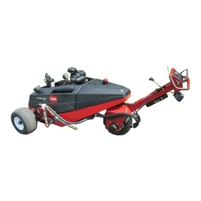
Toro 09802 HydroJect 3010 User manual
Toro
Toro Hydroject 3000 User manual

Toro
Toro GREENS AERATOR 09120 User manual
