Toro 58603 User manual

FormNo.3443-831RevA
RearTineTiller
ModelNo.58603—SerialNo.321000001andUp
Registeratwww.Toro.com.
OriginalInstructions(EN)*3443-831*
ItisaviolationofCaliforniaPublicResourceCode
Section4442or4443touseoroperatetheengineon
anyforest-covered,brush-covered,orgrass-covered
landunlesstheengineisequippedwithaspark
arrester,asdenedinSection4442,maintainedin
effectiveworkingorderortheengineisconstructed,
equipped,andmaintainedforthepreventionofre.
WARNING
CALIFORNIA
Proposition65Warning
Theengineexhaustfromthisproduct
containschemicalsknowntotheStateof
Californiatocausecancer,birthdefects,
orotherreproductiveharm.
Useofthisproductmaycauseexposure
tochemicalsknowntotheStateof
Californiatocausecancer,birthdefects,
orotherreproductiveharm.
Introduction
Thistillerisintendedtobeusedbyresidential
homeownersorprofessional,hiredoperatorsto
breakthroughhardsoilconditionsforplantingand
cultivatinggardens.Usingthisproductforpurposes
otherthanitsintendedusecouldprovedangerousto
youandbystanders.
Readthisinformationcarefullytolearnhowtooperate
andmaintainyourproductproperlyandtoavoid
injuryandproductdamage.Youareresponsiblefor
operatingtheproductproperlyandsafely.
Visitwww.T oro.comformoreinformation,including
safetytips,trainingmaterials,accessoryinformation,
helpndingadealer,ortoregisteryourproduct.
Wheneveryouneedservice,genuineToroparts,or
additionalinformation,contactanAuthorizedService
DealerorT oroCustomerServiceandhavethemodel
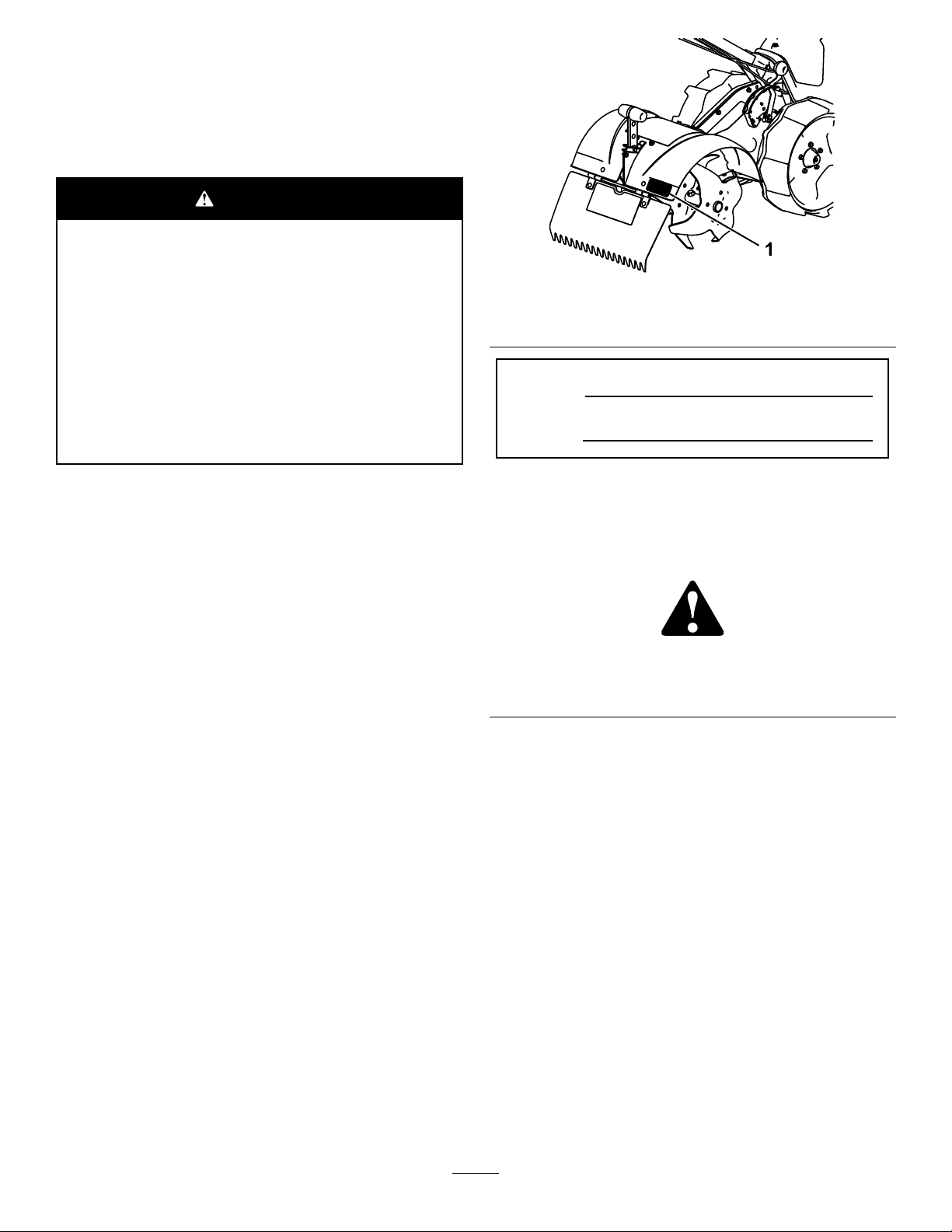
andserialnumbersofyourproductready.Figure1
identiesthelocationofthemodelandserialnumbers
ontheproduct.Writethenumbersinthespace
provided.
g356747
Figure1
1.Modelandserialnumberlocation
ModelNo.
SerialNo.
Thismanualidentiespotentialhazardsandhas
safetymessagesidentiedbythesafety-alertsymbol
(Figure2),whichsignalsahazardthatmaycause
seriousinjuryordeathifyoudonotfollowthe
recommendedprecautions.
g000502
Figure2
Safety-alertsymbol
Thismanualuses2wordstohighlightinformation.
Importantcallsattentiontospecialmechanical
informationandNoteemphasizesgeneralinformation
worthyofspecialattention.
©2021—TheToro®Company
8111LyndaleAvenueSouth
Bloomington,MN554202
Contactusatwww.Toro.com.
PrintedintheUSA
AllRightsReserved

Contents
Safety.......................................................................3
GeneralSafety...................................................3
SafetyandInstructionalDecals..........................4
Setup........................................................................6
1AssemblingtheMachine..................................7
2AddingOiltotheEngine...................................9
ProductOverview...................................................10
Controls...........................................................10
Specications...................................................11
BeforeOperation.................................................12
BeforeOperationSafety...................................12
AddingFuel......................................................13
AdjustingtheHandlebarHeight........................13
DuringOperation.................................................14
DuringOperationSafety...................................14
StartingtheMachine.........................................15
ShuttingOfftheEngine.....................................15
AdjustingtheDragStake..................................15
OperatingTips.................................................16
AfterOperation....................................................16
AfterOperationSafety......................................16
Maintenance...........................................................17
MaintenanceSafety..........................................17
RecommendedMaintenanceSchedule(s)...........17
Pre-MaintenanceProcedures..............................18
PreparingforMaintenance...............................18
Lubrication..........................................................18
GreasingtheMachine.......................................18
EngineMaintenance...........................................19
ServicingtheAirCleaner..................................19
ServicingtheEngineOil....................................20
ServicingtheSparkPlug...................................21
BeltMaintenance................................................22
CheckingandAdjustingtheDrive
Belts..............................................................22
ReplacingtheBelts...........................................23
Cleaning..............................................................26
CleaningtheMachine.......................................26
Storage...................................................................26
StorageSafety..................................................26
StoringtheMachine..........................................26
Troubleshooting......................................................28
Safety
Thismachinehasbeendesignedinaccordancewith
ANSIB71.8-2016.
DANGER
Theremaybeburiedutilitylinesinthework
area.Diggingintothemmaycauseashock
oranexplosion.
Havethepropertyorworkareamarkedfor
buriedlinesanddonotdiginmarkedareas.
Contactyourlocalmarkingserviceorutility
companytohavethepropertymarked(for
example,intheUS,call811forthenationwide
markingservice).
GeneralSafety
Thisproductiscapableofamputatinghandsand
feetandofthrowingobjects.Alwaysfollowallsafety
instructionstoavoidseriouspersonalinjuryordeath.
•Read,understand,andfollowtheinstructions
andwarningsinthisOperator’sManualandon
themachineandattachmentsbeforestartingthe
engine.
•Bethoroughlyfamiliarwiththecontrolsandthe
properuseoftheequipment.Knowhowtostop
themachineanddisengagethecontrolsquickly.
•Donotputyourhands,feet,otherbodyparts,or
clothingnearorundertherotatingtinesorother
movingpartsofthemachine.
•Donotoperatethemachinewithoutallproper
shields,guards,andothersafetyprotective
devicesinplaceandfunctioningproperlyonthe
machine.
•Keepbystanders,especiallysmallchildren,and
petsoutoftheoperatingarea.
•Donotallowchildrentooperatethemachine.
Allowonlypeoplewhoareresponsible,trained,
familiarwiththeinstructions,andphysically
capabletooperatethemachine.
•Shutoffthemachineandwaitforallmovingparts
tostopbeforeyouleavetheoperator’sposition.
Disconnectthespark-plugwire,keepitawayfrom
theplugtopreventaccidentalstarting,andallow
themachinetocoolbeforeadjusting,fueling,
unclogging,servicing,cleaning,orstoringthe
machine.
Improperlyusingormaintainingthismachinecan
resultininjury.Toreducethepotentialforinjury,
complywiththesesafetyinstructionsandalways
payattentiontothesafety-alertsymbol,which
meansCaution,Warning,orDanger—personalsafety
3

instruction.Failuretocomplywiththeseinstructions
mayresultinpersonalinjuryordeath.
SafetyandInstructionalDecals
Safetydecalsandinstructionsareeasilyvisibletotheoperatorandarelocatednearanyarea
ofpotentialdanger.Replaceanydecalthatisdamagedormissing.
decal133-8062
133-8062
decal144-4853
144-4853
1.Engine—shutoff
decal144-4857
144-4857
1.Entanglementhazard,belt—stayawayfrommovingparts;
keepallguardsinplace.
decal144-4861
144-4861
1.Forwardlever
decal144-4862
144-4862
1.Reverselever
4

decal144-4864
144-4864
1.Drivemodeselector;Standard-RotatingTines;Drive;Counter-RotatingTines;Neutral.
decal148-4868
144-4866
1.Warning—readtheOperator’sManual.6.Warning—lookbehindyouwhenoperatingthemachinein
reverse.
2.Warning—alloperatorsshouldbetrainedbeforeoperating
themachine.
7.Warning—donotoperateoverburiedlines.
3.Warning—keepbystandersaway.8.Warning—keepfeetawayfrommovingparts.
4.Warning—stayawayfrommovingparts;keepallguardsin
place.
9.Warning—shutofftheengine,disconnectthesparkplug,and
readtheOperator’sManualbeforeperformingmaintenance.
5.Entanglementhazard,belt—stayawayfrommovingparts.
decal144-4867
144-4867
1.Tostartthemachine,movetheswitchtotheONposition,movethefuel-valvelevertoopen,movethethrottlelevertothe
FASTposition,engagethechoke,placeonehandonthemachineandpulltherecoilhandle,andmovethechokelevertothe
RUNposition.
5

Setup
LooseParts
Usethechartbelowtoverifythatallpartshavebeenshipped.
ProcedureDescriptionQty.Use
Tillerassembly1
Handlebarassembly1
Handlebartube1
Wheel2
Lowerpulleyguard1
Pulleyguardplate1
Dragstake1
Bolt(M8x85mm)1
Bolt(M6x65mm)2
Bolt(M8x16mm)2
Bolt(M6x14mm)4
Nut(M8)1
Nut(M6)4
Screw4
Pin2
1
Lockpin1
Assemblethemachine.
2Engineoil1Addoiltotheengine.
6
1
AssemblingtheMachine
Partsneededforthisprocedure:
1Tillerassembly
1Handlebarassembly
1Handlebartube
2Wheel
1Lowerpulleyguard
1Pulleyguardplate
1Dragstake
1Bolt(M8x85mm)
2Bolt(M6x65mm)
2Bolt(M8x16mm)
4Bolt(M6x14mm)
1Nut(M8)
4Nut(M6)
4Screw
2Pin
1Lockpin
Procedure
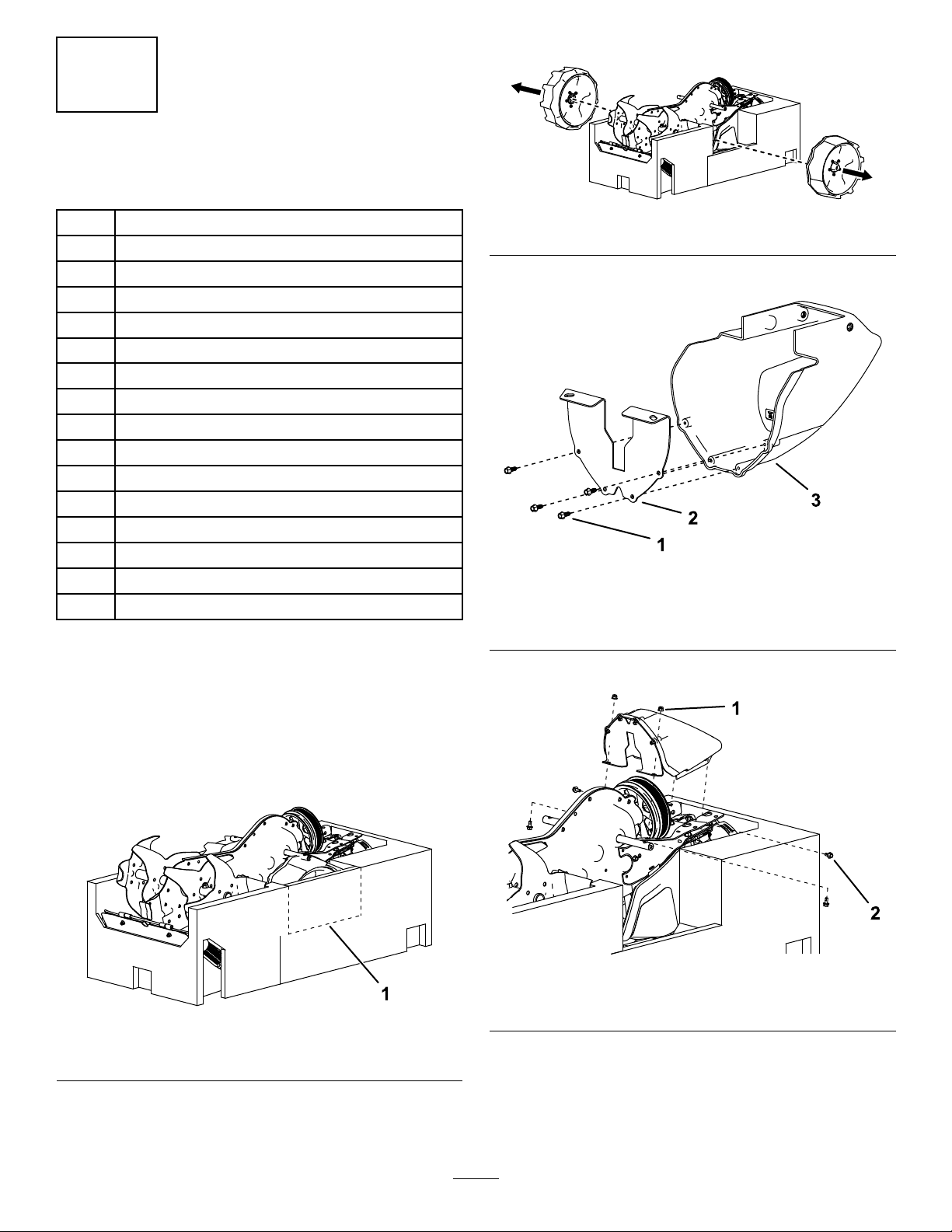
1.Removetheloosepartsfromthetopofthebox.
2.Closethebox,turnitupside-down,andcutit
openatthecorners.
3.Cut,remove,anddiscardtherectangleshown
onbothsidesofthefoam.
g361865
Figure3
1.Cuthere.
4.Removethewheels.
g361871
Figure4
5.Assemblethepulleyguards.
g361864
Figure5
1.Screw(4)3.Lowerpulleyguard
2.Pulleyguardplate
6.Installtheguardstothetillerassembly.
g361866
Figure6
1.Bolt—M6x14mm(4)2.Nut—M6(2)
7

7.Foreachwheel,slideinthepinandsecurethe
wheelwiththebolt.
g361868
Figure7
1.Bolt—M8x16mm(2)2.Pin(2)
8.Turnthemachineoverandremovethefoam.
9.Installthehandlebartubeasfollows:
A.Rotatethespreaderboltclockwise.
g361872
Figure8
1.Spreaderbolt
B.Insertthehandlebartubeintothered
bracketandsecureitasshown.
g361867
Figure9
1.Nut(M8)3.Bolt(M8x85mm)
2.Handlebartube
C.Removeanddiscardthespreaderbolt.
D.Tightenthefastenersuntilthehandlebar
tubeissnug.
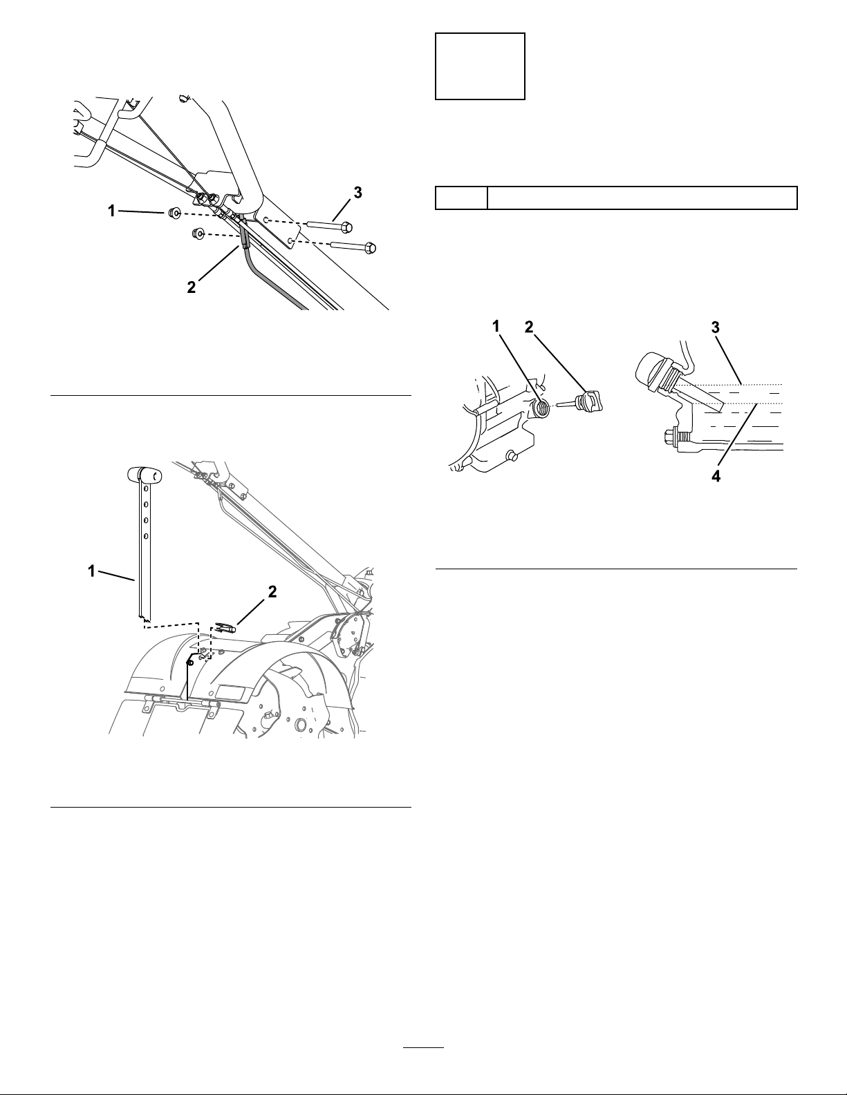
10.Onthehandlebarassembly,connectthecables
tothedriveleversiftheyarenotattached.
g361873
Figure10
1.Reardrivelevercable2.Frontdrivelevercable
8
11.Installthehandlebarassemblyandadjust
theheightasdesired;refertoAdjustingthe
HandlebarHeight(page13).
g361870
Figure11
1.Nut—M6(2)3.Bolt—M6x65mm(2)
2.Wireharnessconnectors
12.Connectthe2wireharnessconnectors.
13.Installthedragstake.
g361869
Figure12
1.Dragstake2.Lockpin
2
AddingOiltotheEngine
Partsneededforthisprocedure:
1Engineoil
Procedure
1.Movethemachinetoalevelsurface.
2.Removethedipstick.
g360549
Figure13
1.Fillertube3.Upperlimit
2.Dipstick4.Lowerlimit
3.Slowlyaddoilintothellertubeuntilitis
overowing.
4.Installthedipstickandtightenit.
9
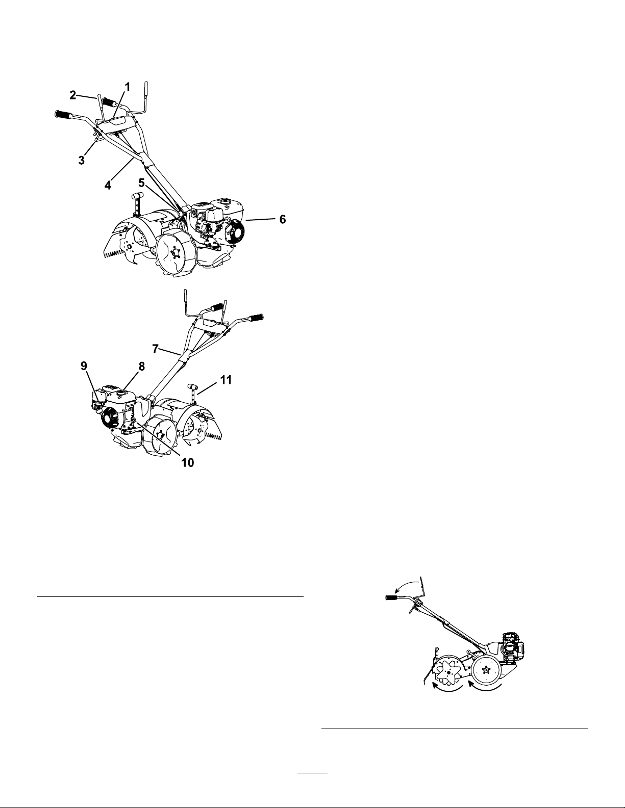
ProductOverview
g356778
Figure14
1.Engineon/offswitch7.Handlebarheight
adjustment
2.Forwardcontrollever8.Fuelcap
3.Rearcontrollever9.Enginecontrols
4.Cableadjustment10.Oil-llcap
5.Drive-modeselectorlever11.Dragstake
6.Recoilhandle
Controls
EngineOn/OffSwitch
UsetheengineOn/Offswitchtoshuttheengineoff.
EnsurethattheswitchisintheONpositionbefore
startingtheengine.
Fuel-ValveLever
MovetheleverforthefuelvalvetotheONposition
beforeattemptingtostarttheengine.Afteroperation,
shutofftheengineandmovethefuel-valveleverto
theOFFposition.
ThrottleControl
Thethrottlecontrolstheenginespeed,andithasa
continuous-variablesetting.
Operatethemachineusingfullthrottleforbest
performance.
ChokeLever
MovethechokeleverontheenginetotheCHOKE
positionwheninitiallystartingacoldengine,then
moveitintotheRUNpositiononcestarted.
Drive-ModeSelector
Shiftthedrive-modeselectorlevertothedesired
modetochangethetransmission.
Important:Donotshiftthedrive-modeselector
leverwhileengagingtheforwardorreverse
controllevers.
•Standard-rotatingtines(SRT):Thewheelsand
tinesarebothengagedwiththeengine;thetines
spininthesamedirectionasthewheels.Usethis
modeforestablishedgardenbedsandtillingin
softsoilconditions.
g356990
Figure15
10
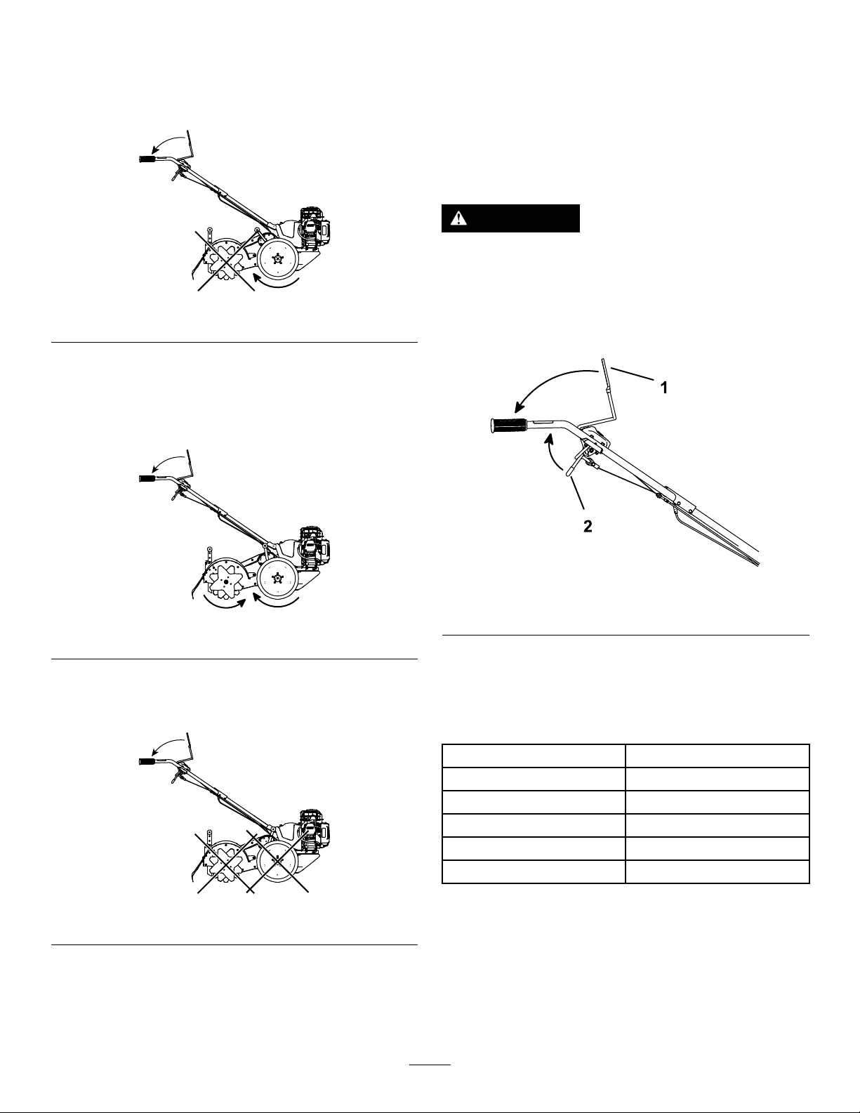
•Drive:Onlythewheelsareengagedwiththe
engine;thetinesaredisengaged.Usethismode
forpoweredtransportationwhendrivingupsteep
inclinesandmovingthemachinetoandfromyour
garden.
g356988
Figure16
•Counter-rotatingtines(CRT):Thewheelsand
tinesarebothengagedwiththeengine;thetines
spinintheoppositedirectionofthewheels.Use
thismodewhenbreakingnewgroundortillingin
compactedsoilconditions.
g356987
Figure17
•Neutral:Thewheelsandtinesareboth
disengagedfromtheengine.Usethismodefor
storageandnon-poweredtransportation.
g356989
Figure18
Drive-ControlLevers
Pulldowntheforwardlevertoengagethetransmission
intheforwarddirection;pulluponthereverseleverto
engagethetransmissioninthereversedirection.
Releasetheleverstodisengagethetransmission.
Important:Donotattempttoengagetheforward
andreverseleversatthesametime.
WARNING
Contactwithmovingtinescanresultin
personalinjury.
Whenmovingthemachineinreverse,watch
forobstaclesbehindyouandkeepyourfeet
awayfromthetines.
g357052
Figure19
1.Forwardlever2.Reverselever
Specications
Specicationsanddesignaresubjecttochange
withoutnotice.
Height103.1cm(40.6inches)
Length158.8cm(62.5inches)
Width50.8cm(20.0inches)
Weight72.6kg(160lb)
Tillingwidth43.2cm(17inches)
Tillingdepth28cm(11inches)
Toensureoptimumperformanceandcontinuedsafety
certicationofthemachine,useonlygenuineT oro
replacementpartsandaccessories.Replacement
partsandaccessoriesmadebyothermanufacturers
couldbedangerous,andsuchusecouldvoidthe
productwarranty.
11

Operation
Note:Determinetheleftandrightsidesofthe
machinefromthenormaloperatingposition.
BeforeOperation
BeforeOperationSafety
GeneralSafety
•Donotallowchildrenoruntrainedadultstooperate
orservicethemachine.Localregulationsmay
restricttheageoftheoperator.
•Usingthismachineisstrenuous.Youmustbein
goodphysicalconditionandmentallyalert.Ifyou
haveanyconditionthatmightbeaggravatedby
strenuouswork,checkwithyourdoctorbefore
operatingthemachine.
•Shutoffthemachineandwaitforallmovingparts
tostopbeforeyouleavetheoperator’sposition.
Disconnectthespark-plugwire,keepitawayfrom
theplugtopreventaccidentalstarting,andallow
themachinetocoolbeforeadjusting,fueling,
unclogging,servicing,cleaning,orstoringthe
machine.
•Becomefamiliarwiththesafeoperationofthe
equipment,operatorcontrols,andsafetysigns.
•Checkthatallguardsandsafetydevices,suchas
deectors,areinplaceandfunctioningproperly.
Donotoperatethemachineunlesstheyare
functioningproperly.
•Knowhowtoshutofftheenginequickly.
•Keepbystanders,especiallysmallchildren,and
petsoutoftheoperatingarea.
•Thoroughlyinspecttheareawhereyouwilluse
themachineandremoveallobjectsthatcould
interferewiththeoperationofthemachineorthat
themachinecouldthrow.
FuelSafety
•Useextremecareinhandlingfuel.Itisextremely
ammableanditsvaporsareexplosive.
•Extinguishallcigarettes,cigars,pipes,andother
sourcesofignition.
•Useonlyanapprovedfuelcontainer.
•Donotremovethefuelcaporaddfueltothetank
whiletheengineisrunningorhot.
•Allowtheenginetocoolbeforellingthefueltank.
•Donotllthefueltankindoors.
•Donotoverllthefueltank.Replacethefuelcap
andtightenitsecurelyafterfueling.Cleanup
spilledfuelbeforestartingtheengine.
•Donotllcontainersinsideavehicleoronatruck
ortrailerbedwithaplasticliner.Alwaysplace
containersontheground,awayfromthevehicle
beforelling.
•Removethemachinefromthetruckortrailer
beforellingthefueltank.Ifthisisnotpossible,
thenaddfuelfromaportablecontainerratherthan
fromafuel-dispensernozzle.
•Keepthefuel-dispensernozzleincontactwith
therimofthefueltankorcontaineropeningat
alltimesuntilfuelingiscomplete.Donotusea
nozzlelock-opendevice.
•Ifyouspillfuelonyourclothing,changeyour
clothingimmediately.
•Ifyouspillfuel,donotattempttostarttheengine;
movethemachineawayfromthespillandavoid
creatingasourceofignitionuntilthefuelvapors
havedissipated.
•Ifyoumustdrainthefueltank,doitoutdoors.
•Storefuelinafuelcontainerandkeepitoutofthe
reachofchildren.
•Donotstorethemachinewithfuelinthefueltank
orfuelcontainerwherethereisanopename,
spark,orpilotlight,suchasonawaterheateror
otherappliance.Allowtheenginetocoolbefore
storingthemachineinanyenclosure.
•Fuelisharmfulorfatalifswallowed.Long-term
exposuretovaporscancauseseriousinjuryand
illness.
–Avoidprolongedbreathingofvapors.
–Keepyourhandsandfaceawayfromthe
nozzleandthefuel-tankopening.
–Keepfuelawayfromyoureyesandskin.
12

AddingFuel
FuelSpecications
TypeUnleadedgasoline
Minimumoctanerating87(US)or91(research
octane;outsidetheUS)
EthanolNomorethan10%byvolume
MethanolNone
MTBE(methyltertiarybutyl
ether)
Lessthan15%byvolume
OilDonotaddtothefuel
Useonlyclean,fresh(nomorethan30daysold),fuel
fromareputablesource.
UsingStabilizer/Conditioner
Usefuelstabilizer/conditionerinthemachinetokeep
thefuelfreshlongerwhenusedasdirectedbythe
fuel-stabilizermanufacturer.
Important:Donotusefueladditivescontaining
methanolorethanol.
Addtheamountoffuelstabilizer/conditionertofresh
fuelasdirectedbythefuel-stabilizermanufacturer.
FillingtheFuelTank
FillthefueltankasshowninFigure20.
g230458
Figure20
AdjustingtheHandlebar
Height
Thehandlebarhas3heightpositionstoaccommodate
varyinguserheights.Whenadjustingtheheight,
notethatduringnormaltillingoperation,theactual
handlebarpositiondropsupto25cm(10inches)from
normalheight.
Removethehardwarefromthehandlebarassembly,
rotatetheassemblytomatchtheholesatthedesired
position,andinstallthehardware.
•Lowheight:UseholesBandC.
•Middleheight:UseholesCandD.
•Highheight:UseholesAandD.
g357053
Figure21
13

DuringOperation
DuringOperationSafety
GeneralSafety
•Useyourfullattentionwhileoperatingthe
machine.Donotengageinanyactivitythat
causesdistractions;otherwise,injuryorproperty
damagemayoccur.
•Donotoperatethemachinewhileill,tired,or
undertheinuenceofalcoholordrugs.
•Wearappropriateclothing,includingeye
protection;longpants;substantial,slip-resistant
footwear;hearingprotection;andgloves.Tieback
longhairanddonotwearlooseclothingorloose
jewelry.
•Keepyourhands,feet,otherbodyparts,and
clothingawayfromrotatingtinesandmovingparts
ofthemachine.Thetinesbeginrotatingwhen
youstarttheengineandmaycontinuetorotate
momentarilyafteryoushutofftheengine.
•Starttheenginecarefullyaccordingtoinstructions
inthisOperator’sManualandwithyourfeetwell
awayfromthetines.
•Useextremecautionwhenreversingorpulling
themachinetowardyou.T oavoidgettingpinned
againstastructure,allowenoughdistanceto
reversedirectionnearawallorfence.
•Keepbystandersoutoftheoperatingarea.Keep
smallchildrenoutoftheoperatingareaandunder
thewatchfulcareofaresponsibleadultwhois
notoperatingthemachine.Stopthemachineif
anyoneentersthearea.
•Beforeyoustarttheengine,ensurethatalldrives
areinneutralandyouareintheoperatingposition.
•Operatethemachineonlyingoodvisibilityand
appropriateweatherconditions.Donotoperate
themachinewhenthereistheriskoflightning.
•Donotattempttoadjustthemachinewhilethe
engineisrunning.
•Ifthemachinestrikesanobjectorstartstovibrate
abnormally,immediatelyshutofftheengine,wait
forallmovingpartstostop,anddisconnectthe
wirefromthesparkplugbeforeexaminingthe
machinefordamage.Vibrationisoftenawarning
signoftrouble.Makeallnecessaryrepairsbefore
resumingoperation.
•Donotoperatethemachineathightransport
speedsonhardorslipperysurfaces.
•Lookbehindanddownandusecarewhen
reversing.
•Donotoverloadthemachinecapacityby
attemptingtotillorcultivatetoodeepandattoo
fastarate.
•Donotpickuporcarryamachinewhiletheengine
isrunning.
•Exercisecautionandbesureofyourfooting,
especiallywhenbackingup,toavoidslippingor
falling.
•Becarefulwhenoperatingthemachineinhard
ground.Thetinescancatchinthegroundand
propelthemachineforward.Ifthisoccurs,letgo
ofthemachine;donottrytorestrainit.
•Exerciseextremecautionwhencrossinggravel
surfaces.Stayalertforhiddenhazardsortrafc.
•Donotleavearunningmachineunattended.
•Shutoffthemachineandwaitforallmovingparts
tostopbeforeyouleavetheoperator’sposition.
Disconnectthespark-plugwire,keepitawayfrom
theplugtopreventaccidentalstarting,andallow
themachinetocoolbeforeadjusting,fueling,
unclogging,servicing,cleaning,orstoringthe
machine.
•Operatetheengineonlyinwell-ventilatedareas.
Exhaustgasescontaincarbonmonoxide,whichis
anodorless,deadlypoison.
•Useonlyaccessoriesandattachmentsapproved
byTheToro®Company.
•Donotchangetheenginegovernorsettingsor
overspeedtheengine.
•Alwaysbesureofyourfooting;keeparmholdon
thehandleandwalk,neverrun.
•Allowthemuferandengineareatocoolbefore
touchingthem.
•Thetinesshouldnotrotatewhentheengineis
idling;iftheydorotate,contactyourAuthorized
ServiceDealer.
•Ifanobjectbecomeslodgedinthetines,shutoff
theengine,disconnectthewirefromthespark
plug,andallowtheenginetocoolbeforeremoving
theobject.
•Donotoperatethemachineonsteepslopes.T o
preventoverturning,operatethemachineupand
downtheslope.
14

StartingtheMachine
1.Movetheengineon/offswitchtotheONposition.
2.Movethefuel-valvelevertotheOPENposition.
3.MovethethrottlelevertotheFASTposition.
4.MovethechokelevertotheCHOKEposition.
Note:Awarmorhotenginemaynotrequire
choking.
5.Pullthestarterhandlelightlyuntilyoufeel
resistance,thenpullthehandlebriskly.Return
thestarterhandlegently.
6.Aftertheenginestarts,graduallymovethe
chokelevertotheRUNpositionandthethrottle
levertotheFASTposition.
ShuttingOfftheEngine
1.Releasethedrive-controllevers.
2.MovethethrottlelevertotheSLOWposition.
3.Movetheengineon/offswitchtotheOFF
position.
4.Movethefuel-valvelevertotheCLOSEDposition.
5.Waitforallmovingpartstostopbeforeleaving
theoperatingposition.
AdjustingtheDragStake
Adjustthedragstakeasneededforthedrivemode.
•CRTmode:Thedragstakehelpsregulatetilling
depthduringCRTmode.Lowerthedragstake
toreducethetillingdepth;raisethedragstaketo
increasethetillingdepth.
•SRTmode:Thedragstakelimitstheforward
speedduringSRTmode.Lowerthedragstaketo
reducetheforwardspeedorifthemachinejerks
forward
•Driveorneutralmode:Raisethedragstake
whentransportingthetiller.
1.Movethemachinetoalevelsurface,shutoffthe
engine,andwaitforallmovingpartstostop.
2.Removethelockpin.
3.Positionthedragstaketothedesireddepth.
Note:Adjustthedragstake1holeatatimeand
testthetilleroperationaftereachadjustment.
Raisingthedragstaketoohighcanresultinloss
ofcontrolofthetiller.
4.Securethedragstakewiththelockpin.
g357054
Figure22
1.Lockpin3.Dragstake—shallowtilling
2.Dragstake—deeptilling
15

OperatingTips
•Inspecttheareawhereyouwillusethemachine
andremoveallobjectssuchaslargerocks,trash,
andbranchesbeforetillingtopreventequipment
damage.
•Donotplaceexcessivebodyweightonthe
machine.Usetheweightofthemachinetotillthe
soilmoreefciently.
•Whentilling,beginwithashallowcutontherst
passandthenincreasethedepthby2.5to5.1cm
(1to2inches)oneachsuccessfulpathuntilyou
reachthedesireddepth.
•Plantgardenrows51to56cm(20to22inches)
aparttoalloweaseofturningattheendofeach
row.
•Whennottilling,movethethrottleleverbetween
halfthrottleandtheSLOWpositiontoextendengine
life,conservefuel,andreducesoundlevels.
AfterOperation
AfterOperationSafety
GeneralSafety
•Shutoffthemachineandwaitforallmovingparts
tostopbeforeyouleavetheoperator’sposition.
Disconnectthespark-plugwire,keepitawayfrom
theplugtopreventaccidentalstarting,andallow
themachinetocoolbeforeadjusting,fueling,
unclogging,servicing,cleaning,orstoringthe
machine.
•Cleandebrisfromthemachinetohelpprevent
res.Cleanupoilorfuelspills.
HaulingSafety
•Disconnectthewirefromthesparkplugbefore
loadingthemachineforhauling.
•Usecarewhenloadingorunloadingthemachine.
16

Maintenance
MaintenanceSafety
•Inspectthemachinefrequentlytoensurethatit
isinsafeworkingconditionandthatshearbolts,
engine-mountingbolts,andotherfastenersare
properlytightened.
•Shutoffthemachineandwaitforallmovingparts
tostopbeforeyouleavetheoperator’sposition.
Disconnectthespark-plugwire,keepitawayfrom
theplugtopreventaccidentalstarting,andallow
themachinetocoolbeforeadjusting,fueling,
unclogging,servicing,cleaning,orstoringthe
machine.
•Wearglovesandeyeprotectionwhenservicing
themachine.
•Nevertamperwithsafetydevices.Checktheir
properoperationregularly.
•Toensureoptimumperformanceofthemachine,
useonlygenuineTororeplacementpartsand
accessories.Replacementpartsandaccessories
madebyothermanufacturerscouldbedangerous,
andsuchusecouldvoidtheproductwarranty.
•Replacetinesthatarebent,damaged,orloose;do
notrepairoralterthem.
•Keepthemachine,attachments,andaccessories
insafeworkingcondition.
•Donotattempttorepairthemachineunless
youhavethepropertoolsandinstructionsfor
disassembling,assembling,andrepairingthe
machine.
RecommendedMaintenanceSchedule(s)
MaintenanceService
IntervalMaintenanceProcedure
Aftertherst5hours•Changetheengineoil.
Beforeeachuseordaily
•Checktheengine-oillevel.
•Cleandebrisfromthemufer,controls,andair-intakegrille.
•Cleanthetineandwheelshafts
Every10hours•Lubricatemovingparts.
•Checkthebelttension.
Every25hours•Servicetheaircleaner(moreoftenindirtyordustyconditions).
•Cleanthepre-cleanerelement.
Every50hours
•Changetheengineoil(moreoftenindustyconditions).
•Replacethebelts.
•Checkthemuferandsparkarrester.
Yearly
•Replacethepre-cleanerelement.
•Replacethefuellter.
•Replacethesparkplug.
•Checkthebelttension.
•Cleantheengineair-coolingsystem(moreoftenindustyconditions).
Important:Refertoyourenginemanualforadditionalmaintenanceprocedures
17
Pre-Maintenance
Procedures
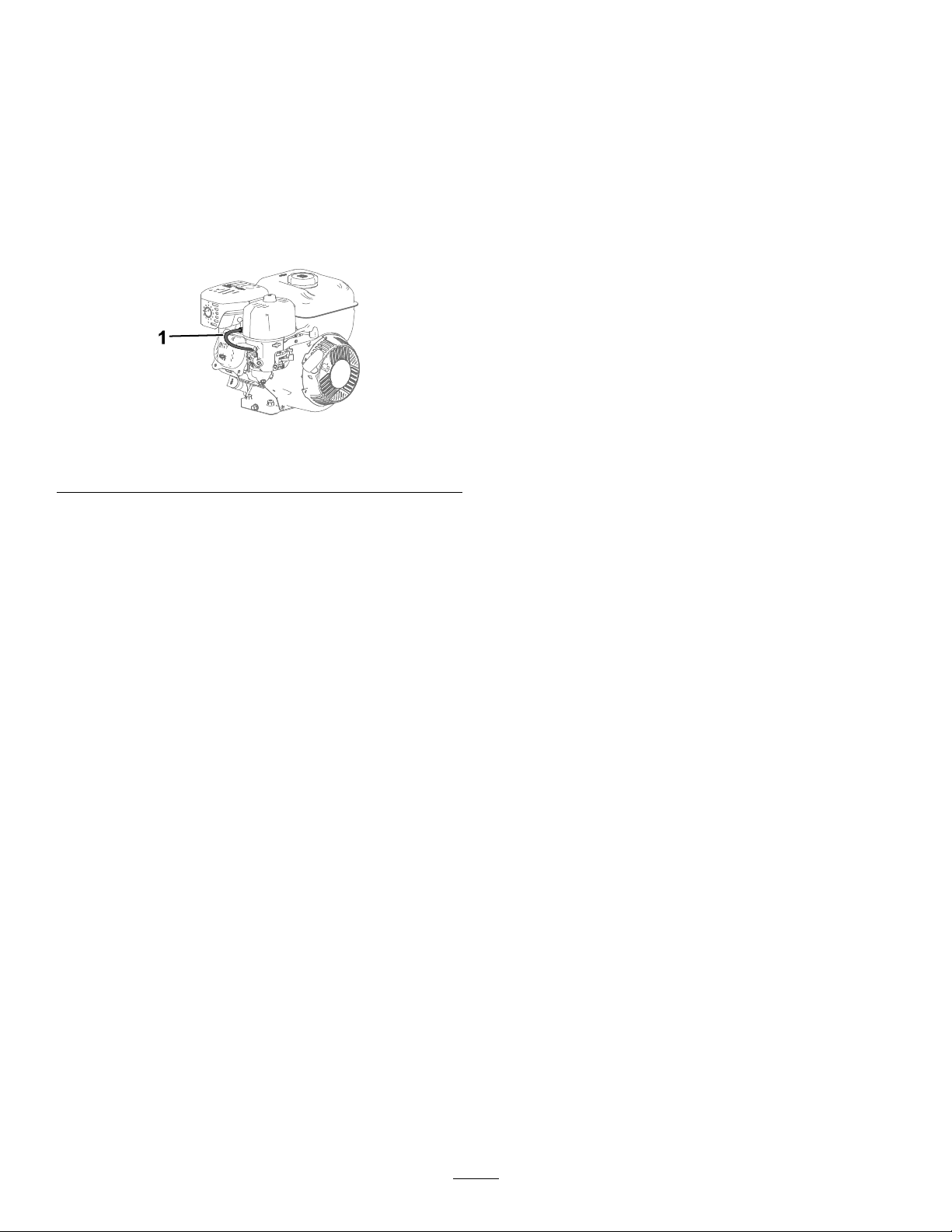
PreparingforMaintenance
1.Movethemachinetoalevelsurface,shutoffthe
engine,andwaitforallmovingpartstostop.
2.Disconnectthespark-plugwirefromthespark
plug.
g361695
Figure23
1.Spark-plugwire
3.Afterperformingthemaintenanceprocedure(s),
connectthespark-plugwiretothesparkplug.
Important:Beforetippingthemachine,
allowthefueltanktorundrythroughnormal
usage.Ifyoumusttipthemachinepriorto
runningoutoffuel,useahandfuelpumpto
removethefuel.
Lubrication
GreasingtheMachine
Greasetype:Whitelithiumgrease
Greasethemachineatthefollowinglocations:
•Forwardandreversearmassemblies
•Forwardandreverseengagementlevers
•Forwardandreversecables.
18

EngineMaintenance
ServicingtheAirCleaner
ServiceInterval:Every25hours/Yearly(whichever
comesrst)—Servicetheair
cleaner(moreoftenindirtyordusty
conditions).
Every25hours/Yearly(whichevercomes
rst)—Cleanthepre-cleanerelement.
Yearly—Replacethepre-cleanerelement.
RemovingtheAirCleaner
Elements
1.Cleanaroundtheair-cleanercovertoprevent
dirtfromgettingintotheengineandcausing
damage.
2.Loosenthefasteneronthecover.
3.Removethecover.
4.Removethefastenerontheelements.
5.Carefullyremovethefoampre-cleanerand
paperelementfromthebase.
g359988
Figure24
1.Cover4.Paperelement
2.Fastener5.Stud
3.Pre-cleaner6.Air-cleanerbase
ServicingtheFoamElement
1.Removethefoampre-cleanerfromthepaper
element.
2.Washthepre-cleanerwithwarmwateranda
milddetergent.
3.Rinsethepre-cleanerandallowittoairdry.
Important:Replacethefoampre-cleanerifitis
tornorworn.Donotoilthepre-cleaner.
ServicingthePaperElement
1.Cleanthepaperelementbytappingitgentlyto
removedust.
Note:Ifitisverydirty,replacethepaper
elementwithanewone.
2.Inspecttheelementfortears,anoilylm,or
damagetotherubberseal.
3.Replacetheelementifitisdamaged.
Important:Donotcleanthepaperelement.
19
InstallingtheAirCleanerElements
1.Installthefoampre-cleanerelementoverthe
paperelement.
Note:Ensurethatyoudonotdamagethe
elements.
2.Installtheair-cleanerelementsontothe
air-cleanerbaseandontothestud.
3.Securetheelementsusingthefastener.
4.Installthecoverandsecureitwiththefastener.
g359988
Figure25
1.Cover4.Paperelement
2.Fastener5.Stud
3.Pre-cleaner6.Air-cleanerbase
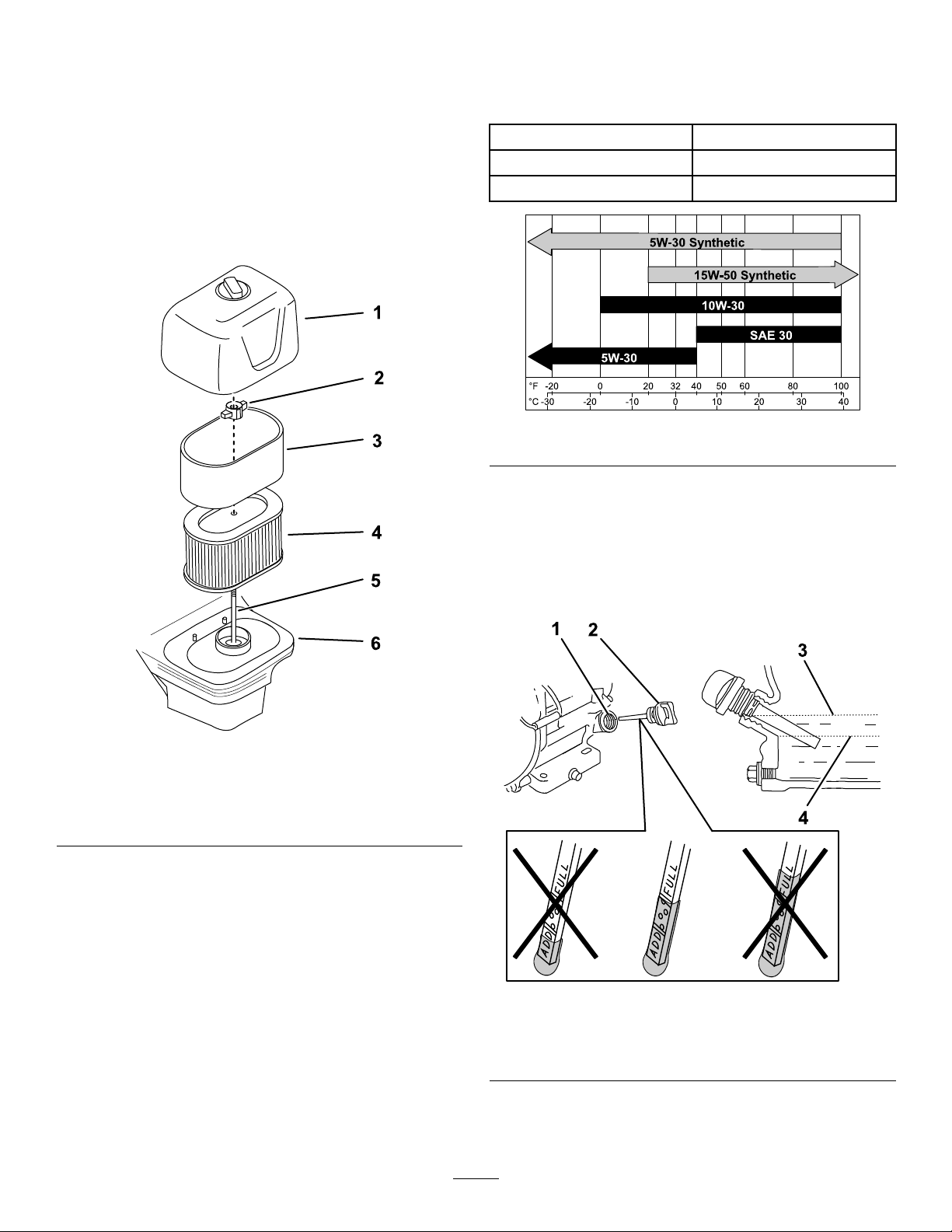
ServicingtheEngineOil
Engine-OilSpecications
Engineoilcapacity0.54to0.59L(18to20oz)
OilviscosityRefertothechartbelow.
APIserviceclassicationSJorhigher
g359987
Figure26
CheckingtheEngine-OilLevel
ServiceInterval:Beforeeachuseordaily
1.Movethemachinetoalevelsurface.
2.Removethedipstickandwipetheendclean.
g360042
Figure27
1.Fillertube3.Upperlimit
2.Dipstick4.Lowerlimit
3.Insertthedipstickfullyintotheoil-lltube,but
donotturnortightenit.
20
Other manuals for 58603
1
Table of contents
Other Toro Tiller manuals


