Toro 07390H Workman HDX-Auto User manual

FormNo.3419-710RevA
Workman®HDX-AutoUtility
Vehicle
ModelNo.07390—SerialNo.401420001andUp
ModelNo.07390H—SerialNo.401420001andUp
ModelNo.07390TC—SerialNo.401420001andUp
Registeratwww.Toro.com.
OriginalInstructions(EN)*3419-710*A

ThisproductcomplieswithallrelevantEuropean
directives;fordetails,pleaseseetheseparateproduct
specicDeclarationofConformity(DOC)sheet.
WARNING
CALIFORNIA
Proposition65Warning
Thisproductcontainsachemical
orchemicalsknowntotheStateof
Californiatocausecancer,birthdefects,
orreproductiveharm.
Theengineexhaustfromthisproduct
containschemicalsknowntotheStateof
Californiatocausecancer,birthdefects,
orotherreproductiveharm.
ItisaviolationofCaliforniaPublicResourceCode
Section4442or4443touseoroperatetheengineon
anyforest-covered,brush-covered,orgrass-covered
landunlesstheengineisequippedwithaspark
arrester,asdenedinSection4442,maintainedin
effectiveworkingorderortheengineisconstructed,
equipped,andmaintainedforthepreventionofre.
Theenclosedengineowner'smanualissupplied
forinformationregardingtheUSEnvironmental
ProtectionAgency(EPA)andtheCaliforniaEmission
ControlRegulationofemissionsystems,maintenance,
andwarranty.Replacementsmaybeorderedthrough
theenginemanufacturer.
Introduction
Thisutilityvehicleisintendedtobeprimarilyused
off-highwaytotransportpeopleandmaterialloads.
Readthisinformationcarefullytolearnhowtooperate
andmaintainyourproductproperlyandtoavoid
injuryandproductdamage.Youareresponsiblefor
operatingtheproductproperlyandsafely.
YoumaycontactTorodirectlyatwww.Toro.com
forproductsafetyandoperationtrainingmaterials,
accessoryinformation,helpndingadealer,orto
registeryourproduct.
Wheneveryouneedservice,genuineToroparts,or
additionalinformation,contactanAuthorizedService
DealerorToroCustomerServiceandhavethemodel
andserialnumbersofyourproductready.Figure1
identiesthelocationofthemodelandserialnumbers
ontheproduct.Writethenumbersinthespace
provided.
Important:Withyourmobiledevice,youcan
scantheQRcodeontheserialnumberdecal(if
equipped)toaccesswarranty,parts,andother
productinformation.
g239323
Figure1
1.Modelandserialnumberlocation
ModelNo.
SerialNo.
Thismanualidentiespotentialhazardsandhas
safetymessagesidentiedbythesafety-alertsymbol
(Figure2),whichsignalsahazardthatmaycause
seriousinjuryordeathifyoudonotfollowthe
recommendedprecautions.
g000502
Figure2
Safety-alertsymbol
Thismanualuses2wordstohighlightinformation.
Importantcallsattentiontospecialmechanical
informationandNoteemphasizesgeneralinformation
worthyofspecialattention.
©2018—TheToro®Company
8111LyndaleAvenueSouth
Bloomington,MN554202
Contactusatwww.Toro.com.
PrintedintheUSA
AllRightsReserved

Contents
Safety.......................................................................4
GeneralSafety...................................................4
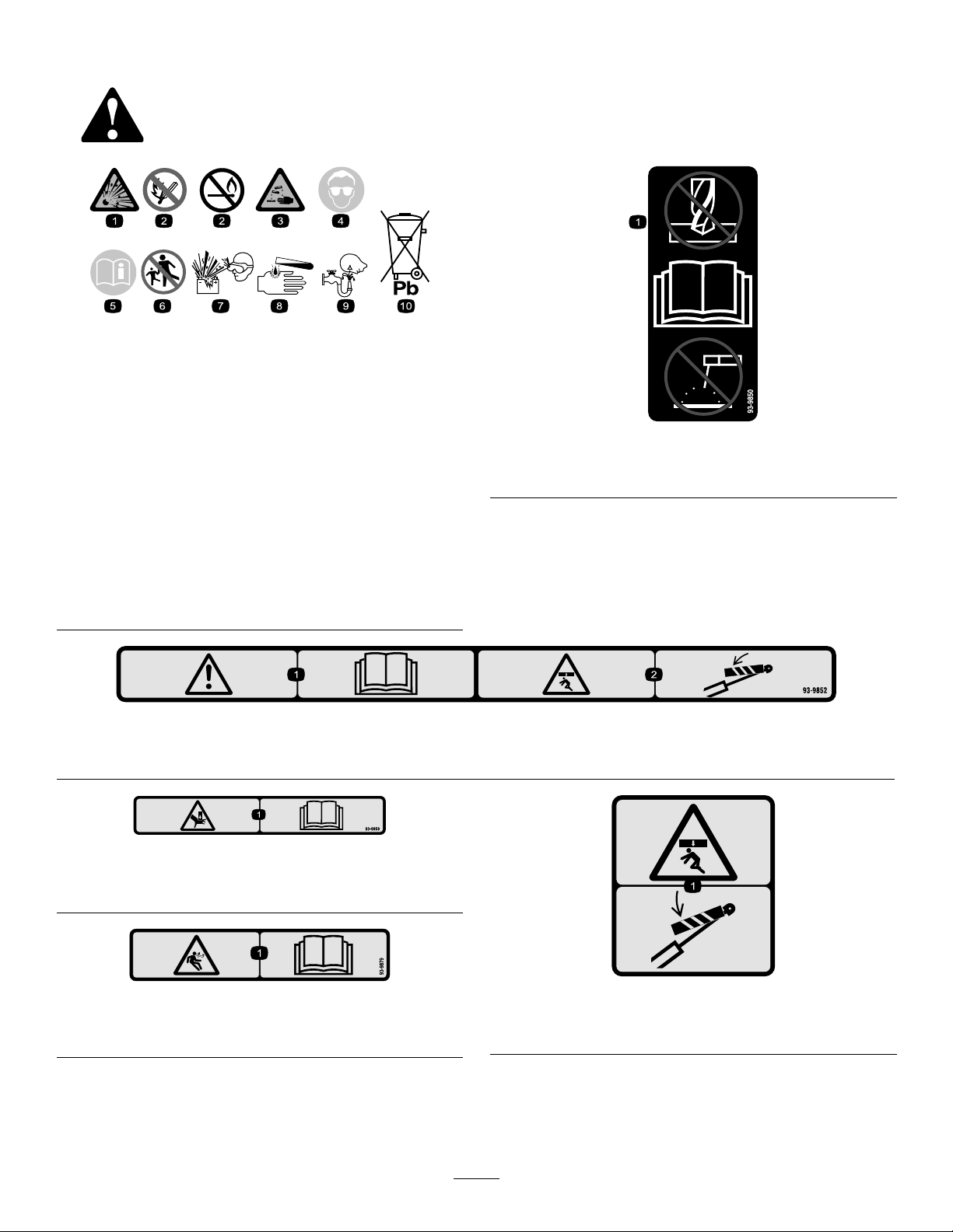
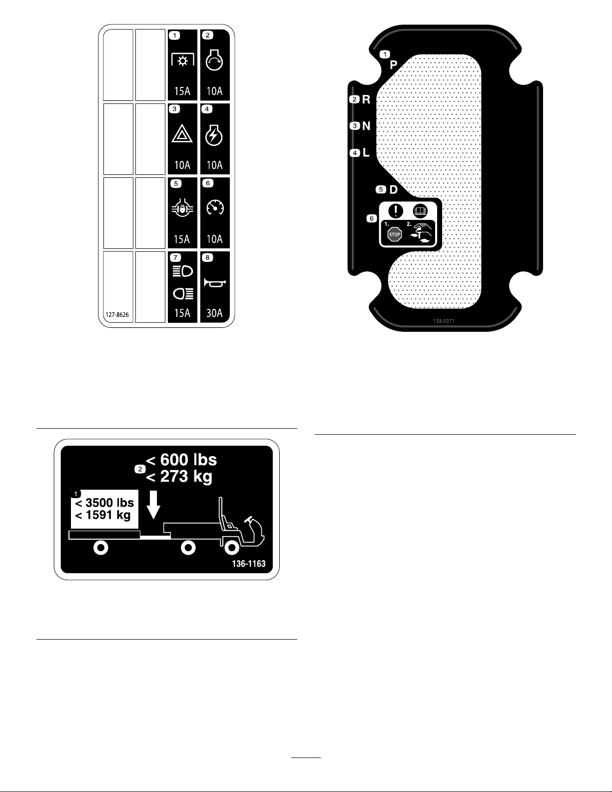
SafetyandInstructionalDecals..........................5
Setup......................................................................10
1InstallingtheSteeringWheel...........................11
2ConnectingtheBattery...................................11
3CheckingtheFluidLevelsandTire
Pressure.......................................................12
4InstallingtheRolloverProtectionSystem
(ROPS).........................................................12
5ConnectingtheCVT-IntakeDuct....................12
6BurnishingtheBrakes....................................13
ProductOverview...................................................14
Controls...........................................................14
ControlPanel................................................16
InstrumentCluster.........................................16
Specications..................................................19
Attachments/Accessories.................................19
BeforeOperation.................................................20
BeforeOperationSafety...................................20
PerformingDailyMaintenance..........................20
CheckingtheTirePressure...............................20
AddingFuel......................................................21
BreakinginaNewMachine..............................21
CheckingtheSafety-InterlockSystem..............22
DuringOperation.................................................22
DuringOperationSafety...................................22
OperatingtheCargoBed..................................24
StartingtheEngine...........................................25
DrivingtheMachine..........................................25
StoppingtheMachine.......................................25
ShuttingOfftheEngine.....................................25
UsingtheSpeed-RangeControl......................26
UsingtheDifferentialLock................................26
UsingtheHydraulicControl..............................27
AfterOperation....................................................29
AfterOperationSafety......................................29
TransportingtheMachine.................................29
TowingtheMachine..........................................30
TowingaTrailer................................................30
Maintenance...........................................................31
RecommendedMaintenanceSchedule(s)...........31
MaintainingtheMachineunderSpecial
OperatingConditions....................................33
Pre-MaintenanceProcedures..............................33
MaintenanceSafety..........................................33
PreparingtheMachineforMaintenance............33
UsingtheBedSupport......................................33
RemovingtheFullBed......................................34
InstallingtheFullBed........................................35
RaisingtheMachine.........................................36
RemovingandInstallingtheHood....................36
Lubrication..........................................................37
GreasingtheBearingsandthe
Bushings.......................................................37
EngineMaintenance...........................................39
EngineSafety...................................................39
ServicingtheAirFilter.......................................39
ServicingtheEngineOil....................................39
CheckingtheOil-Pressure-Warning
Light..............................................................41
ServicingtheSparkPlugs.................................42
FuelSystemMaintenance...................................42
InspectingtheCarbonCanisterAir
Filter..............................................................42
ReplacingtheFuelFilter...................................42
InspectingFuelLinesandConnections.............43
ElectricalSystemMaintenance...........................43
ElectricalSystemSafety...................................43
ServicingtheFuses..........................................44
Jump-StartingtheMachine...............................44
ServicingtheBattery.........................................45
DriveSystemMaintenance..................................46
InspectingtheTires..........................................46
CheckingtheT orqueoftheWheel
Nuts..............................................................46
CheckingtheFrontWheelAlignment................46
MaintainingtheTransmission...........................47
MaintainingtheDifferentialandAxles...............51
CoolingSystemMaintenance..............................52
CoolingSystemSafety.....................................52
CheckingtheEngine-CoolantLevel..................52
RemovingDebrisfromtheCooling
System..........................................................53
ChangingtheEngineCoolant...........................53
BrakeMaintenance.............................................54
CheckingtheBrake-FluidLevel........................54
AdjustingtheParkingBrake..............................55
AdjustingtheBrakePedal.................................56
ControlsSystemMaintenance.............................57
ConvertingtheSpeedometer............................57
HydraulicSystemMaintenance...........................57
HydraulicSystemSafety...................................57
CheckingtheHydraulic-FluidLevel...................57
ReplacingtheHydraulicFilter...........................59
ChangingtheHydraulicFluid............................59
RaisingtheCargoBedinanEmergency...........60
Cleaning..............................................................62
WashingtheMachine.......................................62
Storage...................................................................62
StorageSafety..................................................62
StoringtheMachine..........................................62
Troubleshooting......................................................64
3

Safety
Improperuseormaintenancebytheoperatoror
ownercanresultininjury.Toreducethepotential
forinjury,complywiththesesafetyinstructions
andalwayspayattentiontothesafety-alert
symbol(Figure2),whichmeansCaution,Warning,
orDanger—personalsafetyinstruction.Failureto
complywiththeinstructionmayresultinpersonal
injuryordeath.
ThemachinemeetstherequirementsofSAEJ2258.
GeneralSafety
Thisproductiscapableofcausingpersonalinjury.
Alwaysfollowallsafetyinstructionstoavoidserious
personalinjury.
Usingthisproductforpurposesotherthanitsintended
usecouldprovedangeroustoyouandbystanders.
•Readandunderstandthecontentsofthis
Operator’sManualbeforeyoustarttheengine.
Ensurethateveryoneusingthisproductknows
howtouseitandunderstandsthewarnings.
•Useyourfullattentionwhileoperatingthe
machine.Donotengageinanyactivitythat
causesdistractions;otherwise,injuryorproperty
damagemayoccur.
•Donotputyourhandsorfeetnearmoving
componentsofthemachine.
•Donotoperatethemachinewithoutallguards
andothersafetyprotectivedevicesinplaceand
workingonthemachine.
•Keepthemachineasafedistanceawayfrom
bystanderswhileitismoving.
•Keepchildrenoutoftheoperatingarea.Never
allowchildrentooperatethemachine.
•Stopthemachine,shutofftheengine,andremove
thekeybeforeservicingorfueling.
Improperlyusingormaintainingthismachinecan
resultininjury.T oreducethepotentialforinjury,
complywiththesesafetyinstructionsandalwayspay
attentiontothesafety-alertsymbol,whichmeans
Caution,Warning,orDanger—personalsafety
instruction.Failuretocomplywiththeseinstructions
mayresultinpersonalinjuryordeath.
Youcanndadditionalsafetyinformationwhere
neededthroughoutthismanual.
4

SafetyandInstructionalDecals
Safetydecalsandinstructionsareeasilyvisibletotheoperatorandarelocatednearanyarea
ofpotentialdanger.Replaceanydecalthatisdamagedormissing.
decalbatterysymbols
BatterySymbols
Someorallofthesesymbolsareonyourbattery.
1.Explosionhazard6.Keepbystandersasafe
distanceawayfromthe
battery.
2.Nore,opename,or
smoking
7.Weareyeprotection;
explosivegasescan
causeblindnessandother
injuries.
3.Causticliquid/chemical
burnhazard
8.Batteryacidcancause
blindnessorsevereburns.
4.Weareyeprotection.9.Flusheyesimmediately
withwaterandgetmedical
helpfast.
5.ReadtheOperator's
Manual.
10.Containslead;donot
discard
decal93-9850
93-9850
1.Donotrepairorrevise—readtheOperator'sManual.
decal93-9852
93-9852
1.Warning—readtheOperator’sManual.2.Crushinghazard—installthecylinderlock.
decal93-9868
93–9868
1.Crushinghazardofhand—readtheOperator’sManual.
decal93-9879
93-9879
1.Storedenergyhazard—readtheOperator'sManual.
93-9899
decal93-9899
93-9899
1.Crushinghazard—installthecylinderlock.
5

decal105-4215
105-4215
1.Warning—avoidpinchpoints.
decal105-7977
105–7977
1.Tank2.Pressure
decal106-2353
106-2353
1.Electricalpowerpoint
decal106-6755
106-6755
1.Enginecoolantunder
pressure.
3.Warning—donottouchthe
hotsurface.
2.Explosionhazard—read
theOperator'sManual.
4.Warning—readthe
Operator'sManual.
decal106-7767
106-7767
1.Warning—readtheOperator'sManual;avoidtippingthe
machine;weartheseatbelt;leanawayfromthedirection
themachineistipping.
decal115-2047
115-2047
1.Warning—donottouchthehotsurface.
6

decal115-2282
115-2282
1.Warning—readtheOperator'sManual.
2.Warning—stayawayfrommovingparts,keepallguardsandshieldsinplace.
3.Crushing/dismembermenthazardofbystanders—keepbystandersasafedistanceawayfromthemachine,donotcarry
passengersinthecargobed,keeparmsandlegsinsideofthemachineatalltimes,anduseseatbeltsandhandholds.
decal115-7723
115-7723
1.Warning—thehydraulic-uidpressureis124bar(1,800psi).
2.CouplerA
3.CouplerB
decal115-7739
115-7739
1.Falling,crushinghazard,bystanders—noridersonmachine
decal115-7756
115-7756
1.High-owhydraulics—engaged
decal121-9776
121-9776
1.Warning—readtheOperator’sManualandreceiveproper
trainingbeforeoperatingthemachine.
4.Warning—engagetheparkingbrake,shutofftheengine,and
removethekeyfromthekeyswitchbeforewalkingawayfrom
themachine.
2.Warning—wearhearingprotection.5.Tippinghazard—taketurnsslowly;driveslowlyupandacross
cliffs;withnoload,donotexceed32kph(20mph);while
carryingaloadorwhendrivingonuneventerrain,driveslowly.
3.Firehazard—shutofftheenginebeforerefuelingthemachine.
7

decal121-9890
121-9890
1.Parkingbrake4.Cylinderretract7.Fast
2.Hydraulicsystem—unlock5.Cylinderextend8.Slow
3.Hydraulicsystem—lock6.Transport
decal127-8620
127-8620
1.Headlights4.Horn7.Engine—start
2.Differentiallock—lock5.Engine—shutoff8.Brake
3.Differentiallock—unlock6.Engine—run
8

decal127-8626a
127-8626
1.Powertakeoff(15A)5.Differentiallock(15A)
2.Startengine(10A)6.Speedometer(10A)
3.Hazardlights(10A)7.Headlightsandrearlights
(15A)
4.Engineignition(10A)8.Horn(30A)
decal136-1163
136-1163
1.Donotexceedatransport
loadof1591kg(3,500lb).
2.Donotexceedatongue
weightof273kg(600lb).
decal138-3371
138-3371
1.Park4.Low
2.Reverse5.Drive
3.Neutral6.Attention—readthe
Operator’sManual;stop
themachinebefore
changinggears.
9

Setup
LooseParts
Usethechartbelowtoverifythatallpartshavebeenshipped.
ProcedureDescriptionQty.Use
Steeringwheel1
Cover1
1Washer(5/8inch)1
Installthesteeringwheel(TCandH
modelsonly).
2Nopartsrequired–Connectthebattery(TCandHmodels
only).
3Nopartsrequired–Checktheuidlevelsandtirepressure.
ROPSframe1
4Flange-headbolt(1/2x1-1/4inches)6
MounttheRolloverProtectionSystem
(ROPS).
5Nopartsrequired–Connectthecontinuously-variable
transmissionintakeduct.
6Nopartsrequired–Burnishthebrakes.
MediaandAdditionalParts
DescriptionQty.Use
Operator'sManual1Readbeforeoperatingthemachine.
OperatorTrainingMaterial1Viewbeforeoperatingthemachine.
CVTKit121-98531ConnecttheCVTIntakeDuct(TCandHModelsOnly)
CVTAdapter127-87501ConnecttheCVTIntakeDuct(TCandHModelsOnly)
Note:Determinetheleftandrightsideofthemachinefromthenormaloperatingposition.
10

1
InstallingtheSteering
Wheel
TCandHModelsOnly
Partsneededforthisprocedure:
1Steeringwheel
1Cover
1Washer(5/8inch)
Procedure
1.Ifthecoverisinstalled,removeitfromthehub
ofthesteeringwheel(Figure3).
2.Removethenutfromthesteeringshaft(Figure
3).
3.Slidethesteeringwheelandwasherontothe
steeringshaft(Figure3).
4.Securethesteeringwheeltotheshaftwiththe
nutandtightenitto27to34N∙m(20to25ft-lb).
5.Installthecoveronthesteeringwheel(Figure3).
g024240
Figure3
1.Cover4.Steeringwheel
2.Nut5.Steeringshaft
3.Washer(5/8inch)
2
ConnectingtheBattery
TCandHModelsOnly
NoPartsRequired
Procedure
WARNING
Incorrectlyroutingthebatterycablecould
damagethemachineandcables,causing
sparks.Sparkscancausethebatterygasses
toexplode,resultinginpersonalinjury.
•Alwaysdisconnectthenegativebattery
cable(black)beforedisconnectingthe
positivebatterycable(red).
•Alwaysconnectthepositivebatterycable
(red)rst.
1.Squeezethebatterycovertoreleasethetabs
fromthebatterybase(Figure4).
g010326
Figure4
1.Batterycover
2.Removethebatterycoverfromthebatterybase
(Figure4).
3.Connectthepositivebatterycable(red)tothe
positive(+)terminalofthebatteryandsecure
thecablewiththeboltsandnuts(Figure5).
11

g026250
Figure5
1.Insulatorboot(positive
batterycable)
3.Negativebatterycable
(black)
2.Negativebatterypost
4.Slidetheinsulatorbootoverthepositive
terminal.
Note:Theinsulatorbootpreventsapossible
short-to-groundfromoccurring.
5.Connectthenegativebatterycable(black)tothe
negative(–)terminalofthebatteryandsecure
thecablewithboltsandnuts.
6.Alignthebatterycovertothebatterybase
(Figure4).
7.Squeezethebatterycover,alignthetabsto
thebatterybase,andreleasethebatterycover
(Figure4).
3
CheckingtheFluidLevels
andTirePressure
NoPartsRequired
Procedure
1.Checktheengine-oillevelbeforeandafter
yourststarttheengine;refertoCheckingthe
Engine-OilLevel(page40).
2.Checkthetransmission-uidlevelbeforeyou
rststarttheengine;refertoCheckingthe
Transmission-FluidLevel(page47).
3.Checktheengine-coolantlevelbeforeyou
rststarttheengine;refertoCheckingthe
Engine-CoolantLevel(page52).
4.Checkthebrake-uidlevelbeforeyourststart
theengine;refertoCheckingtheBrake-Fluid
Level(page54).
5.Checktheairpressureinthetires;referto
CheckingtheTirePressure(page20).
4
InstallingtheRollover
ProtectionSystem(ROPS)
Partsneededforthisprocedure:
1ROPSframe
6Flange-headbolt(1/2x1-1/4inches)
Procedure
1.Applymedium-grade(service-removable)
thread-lockingcompoundtothethreadsofthe6
ange-headbolts(1/2x1-1/4inches).
2.AligneachsideoftheROPSwiththemounting
holesoneachsideofthemachineframe(Figure
6).
g009812
Figure6
1.ROPSmountingbracket2.Flange-headbolt(1/2x
1-1/4inches)
3.SecuretheROPSmountingbrackettothe
machineframeusing3ange-headbolts(1/2x
1-1/4inches)oneachside(Figure6).
4.Torquetheange-headbolts(1/2x1-1/4inches)
to115N∙m(85ft-lb).
12

5
ConnectingtheCVT-Intake
Duct
NoPartsRequired
Procedure
Important:Removetheplasticbagcoveringthe
endoftheCVTductbeforestartingtheengine.
TheCVTKit(PartNo.121-9853)andAdapterKit
(PartNo.127-8750)arerequiredforthisprocedure.
1.Loosenthehoseclampsecuringtheplasticbag
attheendoftheCVT-intakehoseandremove
thebag.
2.Raisethecargobedbyperformingthefollowing:
A.Engagetheparkingbrake.
B.Starttheengine.
C.Movethehydraulic-liftleverrearwardto
raisethecargobox.
D.Shutofftheengine.
E.Removethebedsupportfromthestorage
bracketsonthebackoftheROPSpanel
andinstallthesupportontothecylinderrod
ofthebed-liftcylinder;refertoUsingthe
BedSupport(page33).
3.AligntheCVT-intakehoseontotheintake-tube
connectoratthebacksideoftheROPSpanel
andtightenthehoseclamp(Figure7).
g026251
Figure7
1.CVT-intakehose3.Intake-tubeconnector
2.Hoseclamp
4.Removethebedsupport,lowerthebed,shutoff
theengine,andremovethekey.
6
BurnishingtheBrakes
NoPartsRequired
Procedure
Toensureoptimumperformanceofthebrakesystem,
burnishthebrakesbeforeuse.
1.Bringthemachineuptofullspeed,applythe
brakestorapidlystopthemachinewithout
lockingupthetires.
2.Repeatthisprocedure10times,waiting1minute
betweenstops,toavoidoverheatingthebrakes.
Important:Thisprocedureismosteffective
ifthemachineisloadedwith454kg(1,000
lb).
13

ProductOverview
Controls
Note:Determinetheleftandrightsidesofthe
machinefromthenormaloperatingposition.
AcceleratorPedal
Usetheacceleratorpedal(Figure8)tovarytheground
speedofthemachinewhenthetransmissionisin
gear.Pressingdowntheacceleratorpedalincreases
theenginespeedandgroundspeed.Releasingthe
pedaldecreasestheenginespeedandgroundspeed.
g024307
Figure8
1.Brakepedal2.Acceleratorpedal
BrakePedal
Usethebrakepedaltostoporslowthemachine
(Figure8).
CAUTION
Operatingamachinewithwornorincorrectly
adjustedbrakescanmayresultinpersonal
injury.
Ifthebrakepedaltravelstowithin25mm(1
inch)ofthemachineoorboard,adjustor
repairthebrakes.
TransmissionLever
Usethetransmissionlever(Figure9)toshiftthe
transmissionbetweenP(PARK),R(REVERSE),N
(NEUTRAL),L(LOWFORWARD),andD(DRIVE)ground
operation.
Important:Donotshiftthetransmissiontothe
REVERSE,LOW,orDRIVEgearunlessthemachine
ismotionlessandtheengineisatlowidle;
otherwise,youcoulddamagethetransmission.
g028609
Figure9
1.Transmissionlever4.N(neutral)
2.P(park)5.L(lowforward)
3.R(reverse)6.D(drive)
14

Parking-BrakeLever
Wheneveryoushutofftheengine,engagethe
parkingbrake(Figure10)topreventthemachinefrom
accidentallymoving.Ifthemachineisparkedona
steepgrade,ensurethatyouengagetheparking
brake.
•Toengagetheparkingbrake,pullbackonthe
parking-brakelever.
•Todisengagetheparkingbrake,pushthe
parking-brakeleverforward.
Note:Disengagetheparkingbrakebefore
movingthemachine.
•Ifyouparkthemachineonasteepuphillor
downhillgrade,shiftthetransmissionintoP(PARK)
andengagetheparkingbrake.Placechocksat
thedownhillsideofthewheels.
g028610
Figure10
1.Parking-brakelever
Hydraulic-LiftLever
Thehydraulicliftraisesandlowersthebed.Move
thehydraulic-liftleverrearwardtoraisethebed,and
forwardtolowerit(Figure11).
Important:Whenloweringthebed,holdthelever
intheforwardpositionfor1to2secondsafterthe
bedcontactstheframetosecureitinthelowered
position.Donotholdthehydraulicliftintheraise
orlowerpositionformorethan5seconds,once
thecylindersreachtheendoftheirtravel.
g024361
Figure11
1.Lowerthebed4.Unlocked
2.Raisethebed5.Hydraulic-liftlock
3.Locked6.Hydraulic-liftlever
Hydraulic-LiftLock
Thehydraulic-liftlocksecurestheliftlever,sothatthe
hydrauliccylindersdonotoperatewhenthemachine
isnotequippedwithabed(Figure11).Italsolocksthe
liftleverintheONpositionwhenusingthehydraulics
forattachments.
Speed-RangeLever
Usethespeed-rangelever(Figure12)toselect1of
the4work-speedrangesforprecisecontrolofthe
maximumgroundspeedoratransportspeedrange
formovingthemachinebetweenjobsites.
g024320
Figure12
1.Speed-rangelever4.C(mid-highrange)
2.T(transportrange)5.B(mid-lowrange)
3.D(highrange)6.A(lowrange)
15

ControlPanel
g024365
Figure13
1.High-owhydraulics
switch(TCmodelsonly)
6.Off
2.Lightswitch7.On
3.Differentialswitch8.Start
4.Hornbutton(TCmodels
only)
9.Powerpoint
5.Keyswitch
High-FlowHydraulicsSwitch
TCModelsOnly
Pushtheswitchdowntostartthehigh-owhydraulics
andpushtheswitchuptoshutoffthehydraulics
(Figure13).
Note:Youmustsetthehigh-owhydraulicsswitchto
theOFFpositiontostarttheengine.
LightSwitch
Pushthelightswitch(Figure13)totogglethe
headlightsonoroff.
Differential-LockSwitch
Thedifferential-lockswitchallowsyoutolocktherear
axleforincreasedtraction.Pushthedifferential-lock
switch(Figure13)totogglethedifferentiallockonor
off.
Note:Youmaylockandunlockthedifferentialwhile
themachineisinmotion.
HornButton
InternationalModelsOnly
Thehornbuttonislocatedonthecontrolpanel(Figure
13).Pressthehornbuttontosoundthehorn.
KeySwitch
Usethekeyswitch(Figure13)tostartandshutoffthe
engine.T oshutofftheengine,rotatethekeyswitch
counterclockwisetotheOFFposition.
Thekeyswitchhas3positions:OFF,RUN,and
START.RotatethekeyswitchclockwisetotheSTART
positiontoengagethestartermotor.Releasethekey
switchwhentheenginestarts.Thekeyswitchmoves
automaticallytotheONposition.
PowerPoint
Usethepowerpoint(Figure13)topoweroptional12
Velectricalaccessories.
InstrumentCluster
g024370
Figure14
1.Tachometer5.Charge-indicatorlight
2.Hourmeter6.Check-enginelight
3.Speedometer7.Low-oilpressurelight
4.Fuelgauge8.Coolant-temperature
gauge
Tachometer
Thetachometerdisplaysthespeedoftheengine
(Figure14).
Note:Thewhitetriangleindicatesthedesiredengine
speedfor540rpmPTOoperation.
16

g024371
Figure15
1.Enginespeed(rpm)2.3,300rpmfor540rpm
PTOoperation
HourMeter
Thehourmeterindicatesthetotalhoursofmachine
operation.Thehourmeter(Figure14)startsto
functionwheneveryourotatethekeyswitchtotheON
positionoriftheengineisrunning.
Speedometer
Thespeedometerregistersthegroundspeedofthe
machine(Figure14).Thespeedometerisinmph,but
youcaneasilyconvertittokm/h;refertoConverting
theSpeedometer(page57).
Check-EngineLight
Thecheck-enginelight(Figure14)illuminatestonotify
theoperatorofanenginemalfunction.
ContactyourauthorizedT orodistributor.
Oil-Pressure-WarningLight
Theoil-pressure-warninglight(Figure14)illuminates
iftheengine-oilpressuredropsbelowasafelevel
whiletheengineisrunning.
Important:Ifthelightickersorremainson,
stopthemachine,shutofftheengine,andcheck
theoillevel.Iftheoillevelislow,butadding
oildoesnotcausethelighttogooutwhenthe
engineisstarted,shutofftheengineimmediately,
andcontactyourAuthorizedServiceDealerfor
assistance.
Checktheoperationofthewarninglightsasfollows:
1.Engagetheparkingbrake.
2.TurnthekeyswitchtotheON/PREHEATposition,
butdonotstarttheengine.
Note:Theoil-pressurelightshouldglowred.
Ifthelightdoesnotfunction,eitherabulbis
burnedoutorthereisamalfunctioninthe
systemthatyoumustrepair.
Note:Ifenginewasjustshutoff,itmaytake1
to2minutesforthelighttocomeon.
Coolant-TemperatureGaugeandLight
Thecoolant-temperaturegaugeandlightregistersthe
coolanttemperatureintheengineandoperatesonly
whenthekeyswitchisinONposition(Figure14).The
indicatorlightblinksrediftheengineoverheats.
FuelGauge
Thefuelgaugeshowstheamountoffuelinthetank.
ItdisplaysonlywhenkeyswitchisintheONposition
(Figure14).Theredsegmentofthedisplayindicates
alow-fuellevelandtheashingredlightindicatesthat
thefuelinthetankisnearempty.
17

Specications
Note:Specicationsanddesignaresubjectto
changewithoutnotice.
Overallwidth160cm(63inches)
Withoutbed:326cm(128inches)
Withfullbed:331cm(130inches) Overalllength
With2/3bedinrear-mountinglocation:346cm(136inches)
Model07390:866kg(1,905lb)
Model07390H:866kg(1,905lb) Baseweight(dry)
Model07390TC:887kg(1,951lb)
Model07390:1498kg(3,295lb)
Model07390TC:1477kg(3,249lb)
Ratedcapacity(includes91kg(200lb)operator,
91kg(200lb)passenger,andloadedattachment)
Model07090H:1498kg(3,298lb)
Maximumgrossvehicleweight(GVW)2363kg(5,210lb)
Tongueweight:272kg(600lb)
TowcapacityMaximumtrailerweight:1587kg(3,500lb)
Groundclearance18cm(7inches)withnoload
Wheelbase118cm(70inches)
Front:117cm(46inches)
Wheeltread(centerlinetocenterline)Rear:121cm(48inches)
Height191cm(75inches)totopofROPS
Attachments/Accessories
AselectionofToroapprovedattachmentsandaccessoriesisavailableforusewiththemachinetoenhance
andexpanditscapabilities.ContactyourAuthorizedServiceDealerorDistributororgotowww.Toro.comfora
listofallapprovedattachmentsandaccessories.
Toensureoptimumperformanceandcontinuedsafetycerticationofthemachine,useonlygenuineT oro
replacementpartsandaccessories.Replacementpartsandaccessoriesmadebyothermanufacturerscouldbe
dangerous,andsuchusecouldvoidtheproductwarranty.
19

Operation
BeforeOperation
BeforeOperationSafety
GeneralSafety
•Neverallowchildrenoruntrainedpeopleto
operateorservicethemachine.Localregulations
mayrestricttheageoftheoperator.Theowner
isresponsiblefortrainingalloperatorsand
mechanics.
•Becomefamiliarwiththesafeoperationofthe
equipment,operatorcontrols,andsafetysigns.
•Knowhowtostopthemachineandshutoffthe
enginequickly.
•Ensurethatyouandyourpassengersdonot
exceedthenumberofhandholdsequippedonthe
machine.
•Checkthatallsafetydevicesanddecalsarein
place.Repairorreplaceallsafetydevicesand
replaceallillegibleormissingdecals.Donot
operatethemachineunlesstheyarepresentand
functioningproperly.
FuelSafety
•Useextremecareinhandlingfuel.Itisammable
anditsvaporsareexplosive.
•Extinguishallcigarettes,cigars,pipes,andother
sourcesofignition.
•Useonlyanapprovedfuelcontainer.
•Donotremovethefuelcaporllthefueltank
whiletheengineisrunningorhot.
•Donotaddordrainfuelinanenclosedspace.
•Donotstorethemachineorfuelcontainerwhere
thereisanopename,spark,orpilotlight,such
asonawaterheaterorotherappliance.
•Ifyouspillfuel,donotattempttostarttheengine;
avoidcreatinganysourceofignitionuntilthefuel
vaporshavedissipated.
PerformingDaily
Maintenance
Beforestartingthemachineeachday,performthe
EachUse/DailyprocedureslistedinMaintenance
(page31).
CheckingtheTirePressure
ServiceInterval:Beforeeachuseordaily
Fronttiresairpressurespecication:220kPa(32
psi)
Teartiresairpressurespecication:124kPa(18
psi)
Important:Checkthetirepressurefrequently
toensureproperination.Ifthetiresarenot
inatedtothecorrectpressure,thetireswillwear
prematurelyandmaycausethe4-wheeldriveto
bind.
Figure18showsanexampleoftirewearcausedby
under-ination.
g010294
Figure18
1.Under-inatedtire
Figure19showsanexampleoftirewearcausedby
over-ination.
g010293
Figure19
1.Over-inatedtire
20
This manual suits for next models
2
Table of contents
Other Toro Utility Vehicle manuals

Toro
Toro 127-7377 User manual

Toro
Toro Workman HD 07369 User manual

Toro
Toro Dingo TX 525 Manual

Toro
Toro 7383 User manual

Toro
Toro Top Dresser 1800 User manual

Toro
Toro 110-2626 User manual

Toro
Toro 09833 User manual

Toro
Toro Workman 3300-D User manual

Toro
Toro 07390 Workman HDX-Auto User manual

Toro
Toro Workman MDX User manual
Popular Utility Vehicle manuals by other brands

Etnyre
Etnyre BLACKHAWK RTN Series manual

Westward
Westward GO-4 EV INTERCEPTOR IV Operator's manual

Federal Signal Corporation
Federal Signal Corporation LEACH 2R-III Service manual

OFF GRID TRAILERS
OFF GRID TRAILERS EXPEDITION 2.0 owner's manual

MANCO
MANCO 7150 Assembly instructions

Terex
Terex Evoquip Bison 120 Operation manual