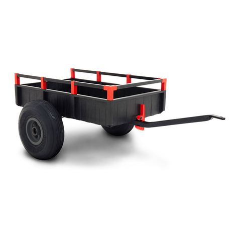
Toro 131-8308 User manual
Other Toro Utility Vehicle manuals
Toro
Toro Workman 07235 User manual
Toro
Toro 07390 Workman HDX-Auto User manual
Toro
Toro TX Platform User manual

Toro
Toro Workman User manual

Toro
Toro 07211TC User manual

Toro
Toro Workman UTX User manual

Toro
Toro 7359 User manual

Toro
Toro Workman GTX User manual
Toro
Toro 7379 User manual
Toro
Toro Twister 12003 User manual
Toro
Toro Workman 07170 User manual
Toro
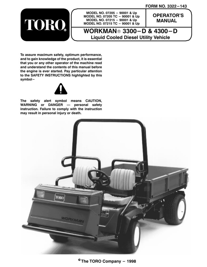
Toro Workman 3300-D User manual

Toro
Toro Workman GTX User manual
Toro
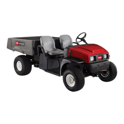
Toro Workman MDX-D User manual

Toro
Toro Workman GTX User manual
Toro
Toro 7362 User manual
Toro
Toro 07277 Workman 2110 User manual
Toro
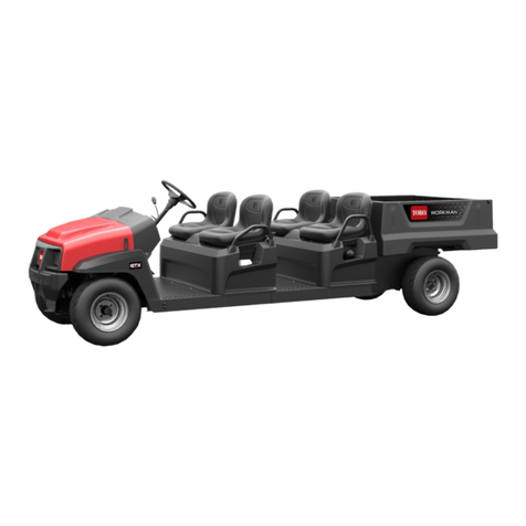
Toro Workman GTX Series User manual
Toro
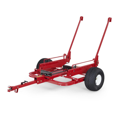
Toro TransPro 200 User manual
Toro
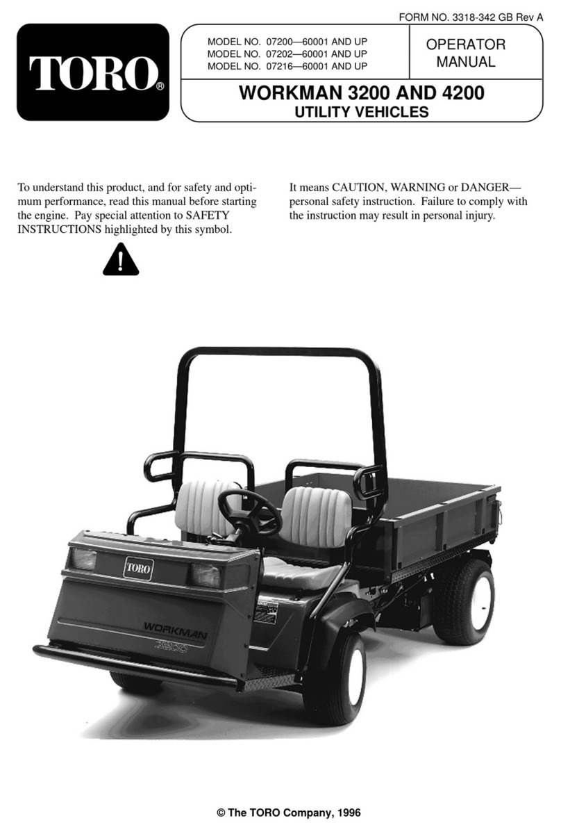
Toro Groundsmaster 7200 Series User manual
Popular Utility Vehicle manuals by other brands
Range Road
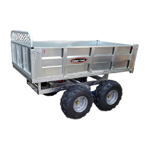
Range Road RR608 Assembly manual

Landoll
Landoll 900D Series Operator's manual

SSI SCHAEFER
SSI SCHAEFER WEASEL LITE user manual

Club Car
Club Car TURF 272 2005 Maintenance service manual

pronovost
pronovost PUMA-10000 Operator's manual

Cushman
Cushman Turf Truckster 84069 Parts & maintenance manual
