manuals.online logo
Brands
  1. Home
  2. •
  3. Brands
  4. •
  5. Toshiba
  6. •
  7. Copier
  8. •
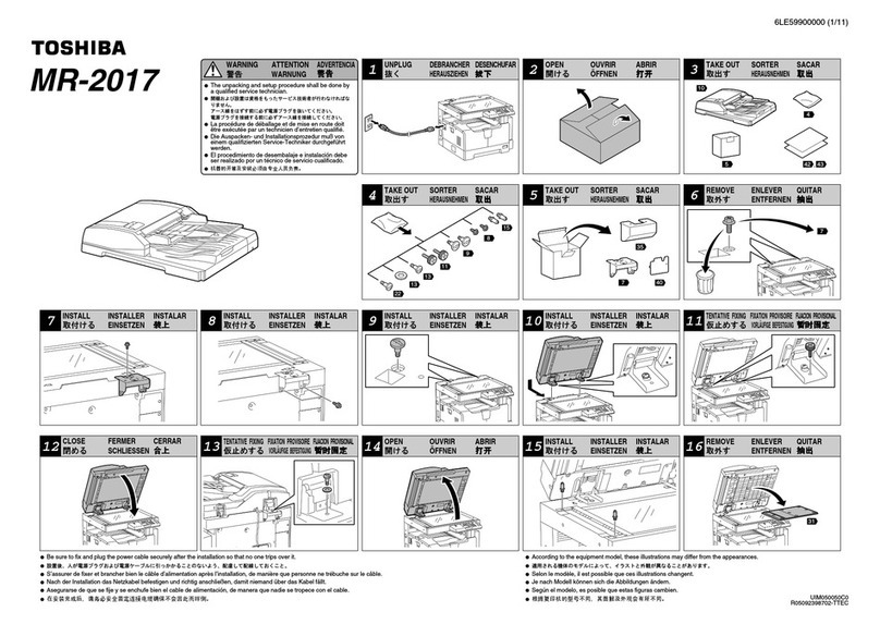
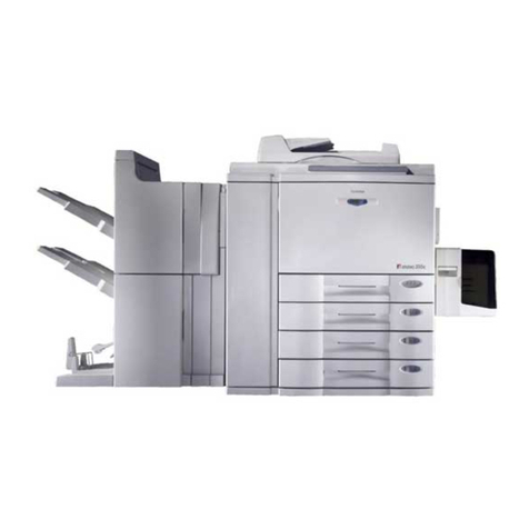
  9. Toshiba 60th Series User manual

Toshiba 60th Series User manual

TOSHIBA THE 60TH SERIES ANALOG COPIERS – THE DISPUTABLE TOSHIBA 1550 COPIER
Following the Toshiba 1360/70 copier, reviewed in the
previous article, comes the Toshiba 1550 copier. As mentioned
in the title, this is a much disputed model – some technicians
love it, others hate it. But nevertheless this is one of the most
common copiers in East Europe (in Bulgaria for sure). This
model is situated in the upper segment of the lower class copiers
and so is designated for small to middle offices and not for copy
and print centers. So the problem with this model arises whet
users try to overwork it. In my practice as a service technician I
have had both good and bad experience with this model.
There are users that never had any issues with the
copier, other than the usual maintenance and periodical
replacements of parts. These users’ monthly copy-volume never
exceeds 5000 to 10 000 copies. The only other issue with such
machines is the dusty environment they often operate in, which
causes periodical cleaning to be performed twice as often as the
normal interval of 60 000 copies. So the conclusion is that is
users don’t overwork their machines and provide them with
regular maintenance, they will serve them longer, causing less
trouble to the service technician that maintains them. Even more
– given the proper maintenance the consumable replacement
parts such as drums, heat rollers etc. can “live” up to twice the
copy count given by the manufacturer. This is the case with the
happy technicians mentioned above.
However there are cases when everything that can go
wrong with this model does. This is the case with machines
often overworked and poorly maintained. Such machines often
operate in poor conditions (dust, humidity etc.) and are used in
copy centers. They age very quickly and the mechanical parts
wear very quickly too. Given the fact that many of the parts in
the machine are made of plastic (a negative tendency fully
developed in later e-Studio models), all this issues are a “recipe
for disaster”.
The good news is that if one knows the weak points of
the machine and the most common places to search for wear and
clean during periodical maintenance, the copier will work
reliably and you will come to like this controversial model. The
most common weak spots and failures of the model will be
discussed in the articles to come. But first let me once more
emphasize the importance of periodical maintenance and the
preventive inspection check – this is the main goal of this article.
PERIODICAL MAINTENANCE – USEFUL PRACTICES
The manufacturer recommends the periodical
maintenance to be performed at 60 000 copies, which is also the
recommended service-live of most of the consumable parts in
the copier:
Inspection every 60,000 copies
(1) Preparation
1) Ask the key operator about the present machine
conditions and note them down.
2) Before starting the maintenance work, make and retain a
few sample copies for later comparison.
3) Turn off the power switch and disconnect the power cord
plug.
(2) The period inspection should be conducted in accordance
with the PERIODIC INSPECTION CHECK LIST shown
below. Perform the inspection by referring to the figures, as
well as to the explanations in the Service Manual of the
machine when necessary.
(3) After the inspection has been completed, plug in the
machine and turn the power switch on, and
confirm the general operation of the machine by making a
few copies and comparing them to those
made previously.
Inspection and over-haul every 180,000 copies
(1) Replace all the cosumables.
(2) Check to see if there is any damage to parts of the drive
section (gear, pulley, timing belt, etc.). Replace parts on
principle if damaged.
(3) Check to see if there is any damage or peeling of adhered
parts (tape, Mylar, etc.). Replace any affected parts.
(4) Check to see if all the switches and sensors operate properly.
Replace them if they are not operating properly.
(5) Clean the inside of the machine thoroughly.
Symbols used in the Periodic Inspection Check List:
1. Optical section cleaning
1.1 Remove screws A and the original glass retaining plate.
Remove the original glass and clean it both sides with
window cleaner. Note – do not remove screws B. They are
used for correction of image skew and registration of the
copy image.
1.2 Remove screw C and the L-shaped plate with it. Remove the
lens cover D, carefully in the direction E, careful not to
break the drive tooth belt of the lens assembly and the
carriage drive wire. See figure 1.
1
1.3 Clean with dry lint free cloth mirrors 1, 2, 3, 4 and 5 as well
as the expo-lamp reflector.
1.4 Clean with isopropyl alcohol the sliders A of the carriage 1
and 2. Note – be careful not to bend carriage 3, because it is
mounted only to the rear side of the copier. Bending will
result in copy image skew. See figure 2.
1.5 Inspect the ends A of the process unit holder that protrude
from the optical unit bottom. If they are broken the process
unit will move from side to side causing image distortion
and excessive wear of the main drive gear assembly. See
figure 3.
A
B
C D
E
2
A
3
A
2. Remove the paper tray.
2.1 Remove the blue knob A of the transfer corotron cleaning
rod.
2.2 Pull the knob B, remove and clean the waste toner container.
Put it back into place.
2.3 Remove the two plastic clips C, holding the pick up and feed
rollers. Remove the rollers, clean them with rubber cleaning
fluid from the accumulated paper dust and dirt and inspect
the surface for wear. A normal surface should be rough, if
not replace the rollers. Reassemble the rollers.
2.4 Inspect the color of the separation roller D. The color is an
indicator of the age of the roller. A new roller should be
blue. For some strange reason they tend to become green as
they age. Note - if you have problems with double sheet
feeding and the color is green, you know what to do. See
figure 4.
3. Main body of the machine
3.1 Remove the wire A by squeezing it in B. Remove screw C
and pull out the process unit. See figure 5.
3.2 Remove screw A and the cover B of the registration
assembly. Underneath unplug one connector and remove a
screw.
3.3 Remove screw C and pull out the 6th mirror cover. Clean it
with window cleaner as well as the mirror itself.
3.4 Push gently the tab D and carefully remove the
transfer/separation corotron assembly.
3.5 Remove the registration assembly by pulling it out in
direction E. See figure 6.
6
C
3.6 Gently remove the ozone filter A in the direction B and clean
it with vacuum cleaner.
3.7 Remove screw C, remove the cover D and remove the screw
underneath. Note – note the hole the screw is fitted in (there
are two holes –a round one and a prolonged one the right is
the round). See figure 7.
3.8 Remove screws A and the exit/fuser cover.
3.9 Unplug connectors B, C and D and remove the fuser unit by
pulling it out in direction E. See figure 8.
4
D
C
B
A
5
C
B
A
D EA
B
7
B
A
D
C
8
E
C
B
D
A
3.10 Remove 3 screws and the cover A. See figure 9.
3.11 Remove corotron assembly spring A.
3.12 Clean the inside of the machine with vacuum cleaner. Note
– clean thoroughly the transfer corotron assembly
terminal B from dust and toner.
3.13 Inspect the inside of the machine around the lower and
upper drive assemblies. Look for broken teeth by hand
cranking the assemblies.
3.14 Clean the filter C of the optical fan with vacuum cleaner as
you hold it with hand, because it is loosely attached. See
figure 10.
3.15 Rotate the machine and remove two screws to detach the
rear cover.
3.16 Clean the rear optical fan filter A the same way as the front
one.
3.17 Clean the rear side of the machine from toner and dust with
vacuum cleaner, especially around the waste toner
discharge assembly B. See figure 11.
11
A
9
A
B
4. Cleaning the modules of the machine
4.1 Push three tabs A and remove the separation charger grid.
Remove the covers B. Clean with vacuum cleaner the
terminals of the corotron assembly.
4.2 Using cotton swabs moistened with window cleaner, wipe
the corotron housing as well as the wires themselves. See
figure 12.
12
A
10
B
4.3 Turn the registration assembly upside down and remove the
cleaning brush A. Clean it with vacuum cleaner. Inspect the
hooks B of the registration roller springs, if they are broken,
that will lead to defects which will be described in the
articles to follow.
4.4 Clean the rubber registration roller with rubber cleaning fluid.
This is important for the correct aligning of the original to
copy beginning. See figure 13 and 14.
C B
13
A
A
4.5 Remove screws A and B and pull out the fuser cleaning
roller cover and the upper heat roller separation fingers
assembly. See figure 15.
4.6 Clean the tips of the separation fingers with acetone.
Remove the cleaning roller assembly A and remove the
roller itself. Make sure not to loose the two bushings. Clean
the roller with vacuum cleaner by applying moderate force
to the roller. Note – be careful when you clean the ends of
the roller not to unwrap the cleaning felt wound around the
roller. If there is so much toner you can’t clean with vacuum
cleaner moisten a cloth with acetone and rub the roller.
Apply moderate amount of silicone oil to the roller felt.
4.7 Remove screws B and remove the fuser roller cleaning blade.
Clean the tip of it with acetone.
4.8 Remove gears C and D, clean the teeth with brush and using
a cotton stab with acetone clean the gear C shaft and the
hole of the gear itself. Note – do not apply any lubricant to
the gear’s shaft. See figure 16.
4.9 Clean with acetone the upper A and lower B guide plates of
the fuser unit. See figure 17.
17
A
5. Image process unit maintenance
5.1 Unplug the connector A. First push the main charger in the
direction B and the lift it careful not to scratch the OPC
Drum. Pull out the assembly in direction C.
5.2 Lift the tabs D and unplug connector E. Pull out the
developer unit in direction F. See figure 18.
5.3 Inspect the developer unit. Check if the roller guides A are
rotating freely. Check if the cover seal B is on top of the
side seals of the developer roller. Clean with vacuum
cleaner the accumulated toner under the magnetic roller as
well as around the side seals C.
5.4 Check if the unit is mechanically sound by rotating the input
gear D in the direction shown. If there is too much torque
needed to turn it, this is an indicator that there are problems
in the unit which will be discussed in following articles. See
figure 19.
B
B
14
18
A A
B
C
B
15
D
F
16
B
19
A
B
D
C
C
A
D
5.5 Remove the main charger grid by applying force in direction
A. Clean the grid by washing it with window cleaner fluid.
Note – when drying it watch for small particles remaining
on the grid. Brush them off if necessary.
5.6 Using cotton swabs with window cleaner wipe the charger’s
housing and the wire itself.
5.7 Clean with alcohol the LED eraser/discharge array. See
figure 20.
Reassemble the modules of the machine in reverse order and
mount them back into the machine. Turn the machine on and
make sure it enters into ready condition. Make a copy of the test
target designed to adjust the copy density. Make copies in all
exposure modes – Auto, Manual (middle position), Dark (max.
right position), Light (max left position) and Photo. If the copy
density in unsatisfactory you should make adjustments in the
following order.
IMAGE DENSITY ADJUSTMENTS
1. Enter the adjustment mode AJ by holding together numerical
buttons 0 and 5 and turning on the machine.
2. Begin with adjustment of the copy density in the middle
position. Make a test copy by pressing the “Energy saver
button”. Change the value of code 1 if the copy is too light
or too dark (the higher the value the lighter the copy
density). The procedure is the following: enter 1 and press
the Start button. Change the value and store it by pressing
the Interrupt button. Make a test copy and readjust if
necessary.
3. Execute the auto exposure auto adjustment procedure – place
a couple of white A3 sheets on the original glass and close
the platen. Enter code 49 and press the start button. After
completion make a test copy. If necessary change manually
the auto exposure density by changing the value in code 5.
4. Adjust the density of darkest and lightest mode using the same
procedure as in 2. The codes are respectively 10 and 9.
5. Adjust the density of the photo exposure – code 14.
6. Exit the AJ mode by pressing the o and 9 buttons or turn off
the machine.
20
A

Other manuals for 60th Series

2

This manual suits for next models

1

Other Toshiba Copier manuals

Toshiba e-studio 45 User manual

Toshiba

Toshiba e-studio 45 User manual

Toshiba e-STUDIO 55 User manual

Toshiba

Toshiba e-STUDIO 55 User manual

Toshiba DP4500 How to use

Toshiba

Toshiba DP4500 How to use

Toshiba GD-1060 How to use

Toshiba

Toshiba GD-1060 How to use

Toshiba e-STUDIO GL-1020 Manual

Toshiba

Toshiba e-STUDIO GL-1020 Manual

Toshiba e-STUDIO 4511 User manual

Toshiba

Toshiba e-STUDIO 4511 User manual

Toshiba e-studio 12 User manual

Toshiba

Toshiba e-studio 12 User manual

Toshiba MR-2017 User manual

Toshiba

Toshiba MR-2017 User manual

Toshiba e-Studio 350 User manual

Toshiba

Toshiba e-Studio 350 User manual

Toshiba e-studio 120 User manual

Toshiba

Toshiba e-studio 120 User manual

Toshiba GA-1120 User manual

Toshiba

Toshiba GA-1120 User manual

Toshiba e-studio 2040c User manual

Toshiba

Toshiba e-studio 2040c User manual

Toshiba e-studio15 User manual

Toshiba

Toshiba e-studio15 User manual

Toshiba 3560 User manual

Toshiba

Toshiba 3560 User manual

Toshiba E-studio 281c Parts list manual

Toshiba

Toshiba E-studio 281c Parts list manual

Toshiba e-STUDIO 450 User manual

Toshiba

Toshiba e-STUDIO 450 User manual

Toshiba e-STUDIO28 User manual

Toshiba

Toshiba e-STUDIO28 User manual

Toshiba 4550 User manual

Toshiba

Toshiba 4550 User manual

Toshiba e-Studio 223CS Installation guide

Toshiba

Toshiba e-Studio 223CS Installation guide

Toshiba e-studio 12 User manual

Toshiba

Toshiba e-studio 12 User manual

Toshiba e-studio 210c User manual

Toshiba

Toshiba e-studio 210c User manual

Toshiba e-STUDIO211c User manual

Toshiba

Toshiba e-STUDIO211c User manual

Toshiba 2060 How to use

Toshiba

Toshiba 2060 How to use

Toshiba e-studio550 User manual

Toshiba

Toshiba e-studio550 User manual

Popular Copier manuals by other brands

Kyocera Mita KM-7530 Operation guide

Kyocera Mita

Kyocera Mita KM-7530 Operation guide

Canon PC880 Operator's manual

Canon

Canon PC880 Operator's manual

Canon NP6621 Service handbook

Canon

Canon NP6621 Service handbook

Xerox 5760 Specifications

Xerox

Xerox 5760 Specifications

Panasonic Workio DP-3510 Information sheet

Panasonic

Panasonic Workio DP-3510 Information sheet

Lanier 5580 Operator's guide

Lanier

Lanier 5580 Operator's guide

Canon NP6551 Operator's manual

Canon

Canon NP6551 Operator's manual

Ricoh NC5006 operating instructions

Ricoh

Ricoh NC5006 operating instructions

Gestetner DSc545 Printer Reference

Gestetner

Gestetner DSc545 Printer Reference

Gestetner 1302 Facsimile Reference

Gestetner

Gestetner 1302 Facsimile Reference

Lexmark MS312 Service manual

Lexmark

Lexmark MS312 Service manual

Ricoh AD1 Reference Operation Manual

Ricoh

Ricoh AD1 Reference Operation Manual

Lanier 5635 Quick reference guide

Lanier

Lanier 5635 Quick reference guide

Sharp SF-2220 Service manual

Sharp

Sharp SF-2220 Service manual

U-Reach CF121 user manual

U-Reach

U-Reach CF121 user manual

Gestetner DSm635sp Fax guide

Gestetner

Gestetner DSm635sp Fax guide

Kyocera ECOSYS P5021cdn Setup guide

Kyocera

Kyocera ECOSYS P5021cdn Setup guide

Gestetner DSm755 General Settings Guide

Gestetner

Gestetner DSm755 General Settings Guide

manuals.online logo
manuals.online logoBrands
  • About & Mission
  • Contact us
  • Privacy Policy
  • Terms and Conditions

Copyright 2025 Manuals.Online. All Rights Reserved.