manuals.online logo
Brands
  1. Home
  2. •
  3. Brands
  4. •
  5. Toto
  6. •
  7. Toilet
  8. •
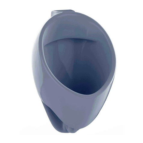
  9. Toto USWN900 Series User manual

Toto USWN900 Series User manual

Conduit E19
(provided on-site)*
(provided on-site)*
Switch box
Back hanger
Controller
Main unit
Upper lid
Sensor surface
Exposure angle and detection area
* For a 300 x 300 mm blank white paper
2019.10CKH6754Installation Manual
USWN900 Series・USWN902 Series
* is for AC type only
Included Parts
Refer to the following and confirm that no parts are missing.
Install the product properly according to these Work Instructions, to ensure that its functions perform sufficiently.
After installation, provide the customer with a clear explanation of how to use the product.
Auto-cleaning Urinal (USWN900 Series・USWN902 Series)
Be sure to install an overcurrent breaker and earth leakage
circuit breaker in order to prevent danger
Electric wire: Use a 600V plastic shielded electric wire or cable
(A ø1.6 mm or ø2.0 mm single wire, or 2.0 mm stranded wire)
Insulate and waterproof the power wire connector
Do not insert the power wire connector inside the device
Doing so may cause electric shock, a current leak, or a re.
Precautions prior to Installation
Do not install in locations of high humidity such as bathrooms
Doing so may cause a malfunction or current leak.
WARNING
・Thoroughly discuss the relevant procedures before performing water and
electrical work.
・The power wire is to be provided on-site. (AC type only)
・A grounding wire is not needed, so use a two-core power wire. (AC type only)
・Water supply pressure ranges from 0.07 MPa (9 L/min [dynamic]) at minimum to
0.75 MPa at maximum. Use the product within this pressure range.
・Be especially careful not to damage the surface of the sensor.
・This product is an electrical appliance. Be careful not to spray water on it.
The exposure angle and detection distance of the sensor are as shown in the
diagram. When installing a handrail or the like in front of the urinal, do so in a way
that does not obstruct the detection areas (both the stable detection area and
unstable detection area) of the photoelectric sensor. Urinal sensors may mal-operate
affected by reflective objects such as mirrors and stainless steel. Cases also happen
when ground reflection caused by these items installed vertically even beyond 3m.
・The product may not function in environments exposed to strong sunlight.
・Inverters or other devices that use infrared light could cause malfunctions.
・A water supply inspection has been conducted prior to packaging. There may be
some water remaining inside the product, but this is normal.
Parts Names
Use prohibited near water
REQUIRED
Always carry out construction work with at least two people
Otherwise, the installer may injure his or her lower back, or drop the porcelain and damage it.
After construction, be sure to give the product a test run and
check that there are no water leaks in any part.
Not installing the product properly may cause water leaks that could result
in ooding damage to property, such as household belongings.
Safety Precautio ns (be sure to read to ensure safety)
WARNING
CAUTION
People other than repair technicians should never disassemble,
repair, or alter the product.
Doing so may cause a malfunction, electric shock, or injury.
Do not install in locations of high humidity such as bathrooms
Doing so may cause a malfunction or current leak.
Read these “Safety Precautions” prior to construction, and install the product correctly. These
Instructions include a variety of safety indications. These are provided so that the product can
be used safely, to prevent harm to customers or others, and to prevent damage to property.
These indications and their meanings are as follows :
CAUTION Ignoring the text accompanying this indication and handling the
product incorrectly could result in serious injury or property damage.
WARNING Ignoring the text accompanying this indication and handling the
product incorrectly could result in death or serious injury.
Indication Meaning
indicates a required step in the use of this product.
indicates a prohibited use of the product.
REQUIRED
Disassembly prohibited
Use prohibited near water
Shutoff valve
Photoelectric
sensor
Decorative bolt
Drain cover
Detection distance exposure
angle 650mm
Pointing down 15°
Unstable detection area
Stable detection area
ø160
15°
ø300
500
Detection
distance
*
“Property damage” refers to damage extending to the home/household property and domestic animals/pets.
Types of safety precautions that must be followed are classied using the two following symbols for explanatory purposes.
Drainage flange
(1) (1)
(1)
Upper lid Drain cover
* e water+ type with sponge
Water supply fixture
Others
Quick fastener
(1)
Shutoff valve
(1)
Back hangers
(2)
Wood screw set
(6 wood screws,
2 washers)
Draining Flange
Washer [large]
(1) (for urinal)
Tapping
screws (4)
Installation
Manual
(1)
Bolt
(1)
Drainage
flange unit
(1)
M8 nuts
(2)
Washer
[small] (1)
P seal
(1)
*For Malaysian Type,
please procure locally.
Instruction
Manual
(1)
Urinal
The symbol to the left indicates the action is “REQUIRED.”
The symbol to the left indicates that “use is prohibited in bathtubs and shower stalls.”
Installation Manual
(1; this document)
Battery only
Alkaline batteries(2)
Battery box (1)
DC Dry Hand this over
to the customer
Water supply pipe inlet
Center line of
the urinal
100
920
until floor
910
until floor
Switch box
installation position * Open a ø15 hole in the
decorative board, and pull
the power wire inside.
* Install so that the water
supply pipe and power
wire do not touch.
ø15 hole
100
(40) or higher
(20)
102
(10)
(10) (10)
54
Center line of the urinal
Pare the foundation wall down
according to the dimensions in the
diagram.
(Unit: mm)
Pare the foundation wall down
2
(Unit: mm)
USWN900 Series USWN902 Series
(Unit: mm)
Water supply position
420
380
50 50
AC type only
Center line of
discharge pipe
920
240
350
100
70
90
Finished
floor surface
Water supply position
920
225
545
23
Finished
floor surface
Continued on other side
Mark the center line of the installation position on the foundation wall.
USWN900 Series
USWN902 Series
Installation Meth od
220-240V AC electrical work is required only for the AC type. Be sure to perform construction steps ①through ③prior to installing the urinal.
* Install the drainage flange according to the included Work Instructions.
Install
switch box
Install shutoff
valve
Install
drainage
flange
Install urinal
unit
Connect
shutoff valve
and valve
①〜③
④
⑤⑥
Check for water
leaks in water supply
connections
⑦
Construction Procedure s
Check
operation
⑩⑪⑫
Insert battery
connected with
power wire
⑧⑨
Configure
preliminary
flushing
Check for water
leaks in drainage
connections
⑬
Installation
complete
Install
upper lid
⑭
(Unit: mm)
Mark the switch box installation position (for wet and dry construction)
1WARNING
The water supply pipe and power wire must not touch
Doing so may cause a malfunction or current leak.
Prohibited
As-tted Drawing
920
485
23
280
Water supply position
390
380
Water supply position
190
AC type only
Center line of
discharge pipe
50 50
70
90
600
360
660
USWN900 Series
USWN902 Series
910 until floor
To raise
How to carry the urinal
To lower
Insert a
piece
of metal
Quick fastener
Screwless conduit Ø19
(provided on-site)
Conduit connector (provided on-site)
Switch box (provided on-site)
Power wire
(provided on-site)
Front view (shutoff valve installed)
Wrap seal material
(G1/2)
Center line of the urinal
Construction
error ± 10 in
vertical/horizontal
directions
(Unit: mm)
Make sure the quick fastener
cover is locked, then fix it in place.
Rotate the quick fastener and
check the connection.
150 mm or less
Power wire
Shutoff valve
Lock
Quick
fastener
Flange
Use the quick fastener to connect the shutoff
valve and valve.
box.

<Installation Method>
If the O-ring is di rtied, damaged , or s ticks out, it could ca us e wa ter leaks that
could result in flooding damage to property, s uch as household belongings.
Connect the shutoff valve and valveInstall the urinal unit (continued) 65
REQUIRED
Do not install the urinal unit from the drainage outlet side.
Doing so could cause water leaks from the drainage ange that could
result in ooding damage to property, such as household belongings.
2
Wrap seal material around the connector
and screw the shutoff valve in the direction
of the arrow.
* Work the shutoff valve
so that it is within the
construction error
tolerance level.
* Install the shutoff valve
parallel to the wall.
There may be cases
where parts touch the
porcelain and cannot
be installed.
①Connect the power wire and switch box
to the conduit connector, pass the power
wire through the conduit, and pull it into
the switch box.
②Fill the area around the switch box with mortar.
Install the switch box and backfill the foundation wall
Install the shutoff valve
Be sure to supply water
through the water supply
pipe to flush out any dirt
prior to installation.
Key points
3
4
Water supply position
Planar view
Parallel to wall
Parallel to wall
33±5mm
± 10 mm in
horizontal direction
± 10 mm in
vertical direction
Install the back hanger to the location shown in the diagram.
Clean the area around the urinal drainage
outlet of dirt and water, then attach the
seal ring to the urinal drainage outlet.
  
Align the centers of the urinal drainage
outlet and drainage flange, then hang
the urinal unit from the back hanger.
Be careful not to tighten the
nut too strongly and crack
the urinal unit.
Be careful that the shutoff
valve does not strike the
urinal unit.
Fix the flange bolt to the lower part
of the urinal with the washer (large)
and nut.
* The washer (large) and nut are
packaged with the drainage flange.
* The hex size of the nut is 13 mm.
A board ratchet wrench with a total
length of 150 mm or less is
recommended to tighten the nut.
Prohibited
Pull the power wire around 25 cm toward the
shutoff valve, in order to make it easier to
connect the power wire and terminal block.
Install the urinal unit
5
CAUTION
CAUTION
Planar view
Drill a pilot hole of around Ø3 at the
marked installation hole position.
* Drilling a pilot hole of around Ø3 will
make it easier to work.
Do not immediately fix the back hanger
with the three wood screws; instead,
temporarily fix it with the elliptic holes
only.
Attach the seal ring onto the urinal
for a trial at rst, hang the urinal from
the back hanger, adjust it to the indicated
position, then fix it in place. If the urinal
does not reach the indicated height,
loosen the back hanger's wooden
screws, then place a metal plate
between it and the wall to adjust it.
Refer to the Installation Manual
attached to the urinal for information
on how to install the quick fastener.
CAUTION
Insert the valve straight into the shutoff valve.
* Use a switch box for a single device
(no cover).
* A grounding wire is not needed, so
use a two-core power wire.
* Use a screwless conduit (nominal
designation, provided on-site).
* Leaving around 40 cm of slack outside
the box, wind the power wire inside the box.
Align the flanges on the shutoff valve and valve,
then insert the quick fastener.
* If the valve is not fully inserted, it will be impossible
to install the quick fastener.
Confirm that the flange is fully inserted into the
recess on the quick fastener, rotate it to the front and
rear, then check the connection between the shutoff
valve and valve.
If the quick fastener does not rotate
smoothly after connecting it, reconnect it
If the quick fastener is not connected properly,
water leaks could result in ooding damage to
property, such as household belongings.
Install the quick fastener properly, then
check visually or through other means.
REQUIRED
120mm 545mm 225mm
95mm
*3
280mm 485mm
*1 (size) *2 (size) *3 (size)
Use a level or other instrument to install the back
hanger so that its upper surface is level.
Measurement from
center of drainage
outlet *2
Elliptic holes
*1 *1
・
Sponge Decorative
bolt
Fastening
fixture
* There are
fastening fixtures
on both ends.
Wall
Sponge
Number sticker
Reverse side of upper lid
Upper lid
Fastening fixture
Packing
Decorative bolt
Fastening fixture
assembly
Slip washer
*1: DC Dry Battery type flashes;
AC type stays lit
Check for water
leaks here
Fastening bolt
Fastening hole
Around
8 mm
Controller
Press
Power wire
Shutoff valve
CAUTIO N
Prohibited
Do not remove the terminal
block cover covering the
terminal block
Touching the terminal block
may cause electrical shock.
Controller
<
Connecting the power wire
>
Terminal block
cover
Power
wire
Terminal
block
②
①




Terminal block cover
ON
1 2 3 4
Waterproof cover
Switch
Controller
The detection range is automatically adjusted when the power is turned on.
* The photoelectric sensor's automatic detection range adjustment function
operates soon after power is activated. If the photoelectric sensor lamp
continues to flash or stay lit *1 when the unit detects something other than a
human, this means that the detection range is currently being adjusted. Be
careful that the sensor is not triggered by a human before the lamp turns off.
*
If a human is detected when the lamp is flashing or lit *1,
it will take longer to adjust the detection range.
Adjustment is complete when the lamp turns off.

Hold the fastening fixture down from inside the
urinal, then use a hex wrench (nominal
designation 4) to loosen the decorative bolt.

Bring the decorative bolt to the outside.
(Reference: Gap of approximately 8 mm)

While pressing the sponge attached to the rear
surface of the upper lid against the wall, place
the lid.

Use a hex wrench to turn the decorative bolt,
then fasten the urinal unit and upper lid.
*
Be careful not to tighten the decorative bolt too
strongly and crack the urinal unit or upper lid.
*
If there is a gap between the upper lid and
urinal unit after fastening the upper lid, loosen
the decorative bolt, then tighten both sides
again equally until there is no gap.
*
Install only the upper lid that came packaged
with the unit. The upper lid and urinal unit are
manufactured together as a single unit. Using
an upper lid other than the one packaged with
the unit could cause looseness.
*
Use the numbers on the number stickers
attached to the storage side surface of the
urinal unit and the underside of the upper lid to
check the combination.

If the fastening fixture is removed, refer to the
diagram to the left for assembly.
Adjust the photoelectric sensor detection range
10
12
Install the upper lid
14
Configure preliminary flushing (continued)
13
Configure preliminary flushing (switch as needed)
13
Run the electric wire so
that it does not hang over
the top of the shutoff valve.
Be sure to turn the
power on with water
being supplied.
CAUTION
Key points
If the waterproof
cover is removed,
cover the controller.
CAUTION
Remove the waterproof cover.
Insert the alkaline battery into the battery box, then connect the controller
connector and battery box connector.
* For 10 minutes after connecting the battery box, the LED flashes during
photoelectric sensor detection to enable the detection status to be confirmed.
The lamp does not flash even when it detects something after this 10 minute
period.
Install the
waterproof
cover.
Controlle r
Waterproof cover
Controller
Battery box
① ② ③
Insert battery (DC Dry Battery type only)
9
Prohibited
Do not pull the battery box electric wires
Doing so may di sconnect the wires or
terminals, or cause fire or electrical sh ock.
CAUTION
Trigger the photoelectric sensor and confirm that the urinal flushes.
* AC type units will automatically flush the urinal immediately after electric current is applied.
Confirm the above once automatic flushing is complete immediately after electric current is applied.
* If the photoelectric sensor flashes when it has not detected a human, this means that the
photoelectric sensor is automatically adjusting the detection range. Wait until the lamp
stops flashing. (See “ Adjust the photoelectric sensor detection range” for more details)
* If the urinal has a manual flush button, after confirming that the urinal flushes by
photoelectric sensor detection, confirm that the urinal flushes when the button on the
right side of the urinal is operated.
10
Manual
(Singapore
Type only)
ush
button
Confirm that the urinal flushes
11
Sensor not flashing Sensor detection Flush w/ button
Remove the waterproof cover.
Slide the controller up.
Open the setting switch cover on the
controller, and turn switch 1 ON.
After setting the switch, return the
waterproof cover, controller, and
setting switch cover to their original
positions.
* Switches 2 through 4 have no effect
on the preliminary flushing setting.
If switches 2 through 4 are mistakenly
turned ON, be sure to turn them OFF.
*The preliminary flushing switch
is set to “OFF” by default.
After confirming that there are no pipe connection problems, supply water
through the piping, and confirm that there are no water leaks in the connections
between the piping and shutoff valve, and between the shutoff valve and valve.
Check for water leaks in the drainage connections
Take the power wire out of the
switch box, pass it through the
rear of the waterproof cover,
and connect it to the two
terminals (①and ②).
* Cut the power wire if it is too
long.
* Strip the gray covering on the
power wire 25 to 30 mm from
the end. This will make it
easier to connect the power
wire and terminal block.
CAUTION
Confirm that no current is applied before connecting the power wire
Failure to do so may cause electrical shock.
The power supply terminal block and primary power supply must be connected by a qualified person only
Failure to do so may cause a malfunction or electric shock.
When inserting the power wire (VVF) into the terminal block,
insert the grounded side of the wire into the white line side,
and the non-grounded side of the wire into the black line side
Failure to do so may cause re.
Connect the power wire (AC type, e water+ type)
8
REQUIRED
WARNING
When removing the power wire, always be sure to press the white part
on the surface of the power supply terminal block with a flat-head
screwdriver, then remove the wire.
Pulling the power wire out with unreasonable force may cause damage to the controller.
REQUIRED
Black line
White line
<Removing the power wire>
After confirming that there are no pipe connection problems, supply water through the piping, and confirm that there
are no water leaks in the connections between the piping and shutoff valve, and between the shutoff valve and valve.
Check for water leaks in the water supply connections
7
Around 25 to 30 mm
Around 10 to 15 mm
Other manuals for USWN900 Series

4

This manual suits for next models

3

Other Toto Toilet manuals

Toto CS735 Series User manual

Toto

Toto CS735 Series User manual

Toto MS604114CEFG User manual

Toto

Toto MS604114CEFG User manual

Toto washlet User manual

Toto

Toto washlet User manual

Toto CST412MF 10 Series Installation instructions

Toto

Toto CST412MF 10 Series Installation instructions

Toto WASHLET SW3074T40 User manual

Toto

Toto WASHLET SW3074T40 User manual

Toto CST746 User manual

Toto

Toto CST746 User manual

Toto CWT4263074CMFG User manual

Toto

Toto CWT4263074CMFG User manual

Toto USWN925 Series User manual

Toto

Toto USWN925 Series User manual

Toto SoftClose 0GU543 User manual

Toto

Toto SoftClose 0GU543 User manual

Toto CS300D Series User manual

Toto

Toto CS300D Series User manual

Toto NEOREST TCF996RWG/RWSW User manual

Toto

Toto NEOREST TCF996RWG/RWSW User manual

Toto NEOREST 750H User manual

Toto

Toto NEOREST 750H User manual

Toto CST474CEF Instruction Manual

Toto

Toto CST474CEF Instruction Manual

Toto CST614 Series User manual

Toto

Toto CST614 Series User manual

Toto C887 Series User manual

Toto

Toto C887 Series User manual

Toto CST484CEMF Installation instructions

Toto

Toto CST484CEMF Installation instructions

Toto NEOREST 500 User manual

Toto

Toto NEOREST 500 User manual

Toto NEOREST SE User manual

Toto

Toto NEOREST SE User manual

Toto NEOREST User manual

Toto

Toto NEOREST User manual

Toto MS989CUMFG User manual

Toto

Toto MS989CUMFG User manual

Toto NEOREST 600 MS990CG User manual

Toto

Toto NEOREST 600 MS990CG User manual

Toto NEOREST LS User manual

Toto

Toto NEOREST LS User manual

Toto MS855CD Series User manual

Toto

Toto MS855CD Series User manual

Toto Aquia CST412MF Installation instructions

Toto

Toto Aquia CST412MF Installation instructions

Popular Toilet manuals by other brands

NATURE LOO CLASSIC 650 Installation and operation manual

NATURE LOO

NATURE LOO CLASSIC 650 Installation and operation manual

DURAVIT Rimless ME by Starck Dry 2814300000 Mounting instructions

DURAVIT

DURAVIT Rimless ME by Starck Dry 2814300000 Mounting instructions

TECE TECEone operating instructions

TECE

TECE TECEone operating instructions

BIOLAN SIMPLETT Instructions for use

BIOLAN

BIOLAN SIMPLETT Instructions for use

BEMIS bioBidet SLIM ONE owner's manual

BEMIS

BEMIS bioBidet SLIM ONE owner's manual

Glacier bay TL-6900-EW manual

Glacier bay

Glacier bay TL-6900-EW manual

Kohler C3-430 manual

Kohler

Kohler C3-430 manual

MSW Motor Technics MSW-M-PT-13L-20L user manual

MSW Motor Technics

MSW Motor Technics MSW-M-PT-13L-20L user manual

Roper Rhodes MINERVA Fitting instructions

Roper Rhodes

Roper Rhodes MINERVA Fitting instructions

Dometic SeaLand MasterFlush IT 8100 Series Operation manual

Dometic

Dometic SeaLand MasterFlush IT 8100 Series Operation manual

Kohler K-5401TW-2-0 installation guide

Kohler

Kohler K-5401TW-2-0 installation guide

Cinderella Classic NA user manual

Cinderella

Cinderella Classic NA user manual

Wolfen 800 CCBTW Series installation manual

Wolfen

Wolfen 800 CCBTW Series installation manual

OVE E323 installation manual

OVE

OVE E323 installation manual

Swiss Madison Concorde SM-1T106 installation instructions

Swiss Madison

Swiss Madison Concorde SM-1T106 installation instructions

Swiss Madison Vivante SM-STS01 installation instructions

Swiss Madison

Swiss Madison Vivante SM-STS01 installation instructions

Dometic SANIPOTTIE 960 Series instruction manual

Dometic

Dometic SANIPOTTIE 960 Series instruction manual

FV E181 quick start guide

FV

FV E181 quick start guide

manuals.online logo
manuals.online logoBrands
  • About & Mission
  • Contact us
  • Privacy Policy
  • Terms and Conditions

Copyright 2025 Manuals.Online. All Rights Reserved.