tousek ST 80A Guide

Installation and connection manual
Barrier control unit
ST 80A, ST 80VA
in combination with trac light control STA 11

- 2 - tousek / EN_ST-80A_04 / 25. 03. 2020
Index
General warning and safety details ........................................................................................................................ 3
1. Notes, general characteristics, Technical data ST 80(V)A und STA 11 ................................................. 4
2. TraclightcontrolboardSTA11,function ............................................................................................ 5
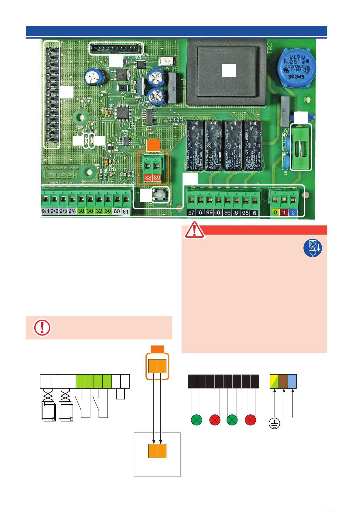
2.1 Controlboardoverviewandterminalassignment.................................................................................. 6
2.2 Connectionsandadjustments .................................................................................................................. 7
induction loop input (outside: term. 9/1+9/2, inside: term.9/3+9/4)................................................ 7
impulse button input (outside: term. 38/30, inside: term. 32/30).................................................... 7
Trac light outputs ......................................................................................................................... 7
Connection of trac light control to barrier control unit (term. 88/89)............................................. 7
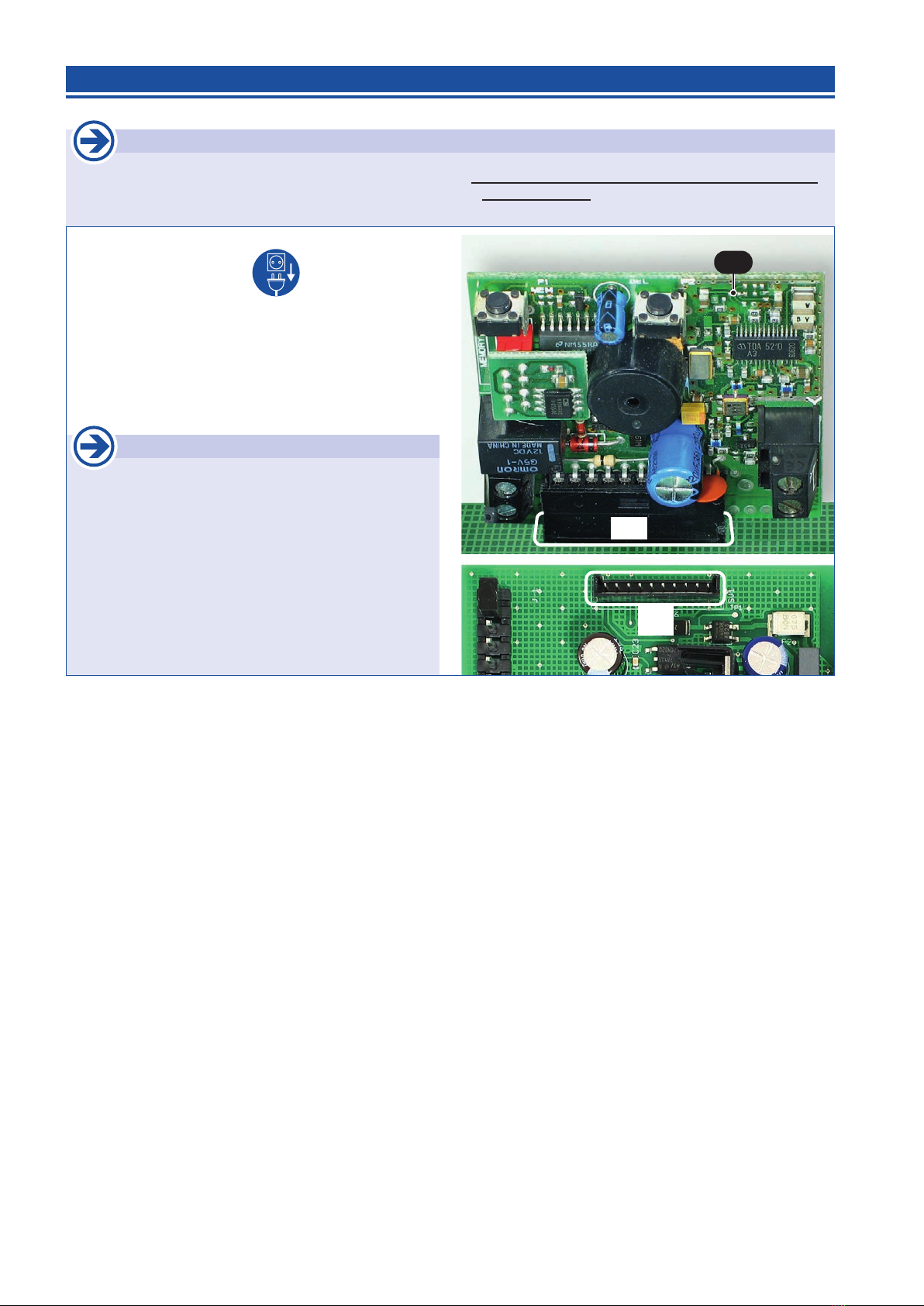
2.3 Radioreceiver(optional) ........................................................................................................................... 8
3. BarriercontrolunitST80(V)A,controlboardlayout ........................................................................... 10
3.1 Terminalassignment, connection notes ................................................................................................11
3.2 Adjustments-overview ........................................................................................................................... 12
Programming keys, program menu, basic settings ...................................................................... 12
Menus .......................................................................................................................................... 13
3.3 Connectionsandadjustments ................................................................................................................ 14
Switches/buttons
....................................................................................................................................... 15
Barrierdoorcontactforsafety(terminal30/54) ...................................................................... 15
ISD channel 1 (I-loop 1: terminals 9/1 and 9/2)........................................................................... 15
ISD channel 2 (I-loop 2: terminals 9/3 and 9/4)........................................................................... 15
STOPP-button (terminals 31/37) ................................................................................................. 15
Safety .......................................................................................................................................... 16
G Photocell (contact: terminals 45/46) ............................................................................................. 16
Photocells - connection examples ......................................................................................... 16, 17
G Main closing edge (terminals 50/52)............................................................................................ 18
PHC/ISD-function ......................................................................................................................... 18
PHC/ISD-pause time .................................................................................................................... 18
PHC test ....................................................................................................................................... 18
Motor .......................................................................................................................................... 19
max. force..................................................................................................................................... 19
ARS response time ...................................................................................................................... 19
Speed OPEN................................................................................................................................ 19
Speed CLOSE.............................................................................................................................. 19
Soft runtime .................................................................................................................................. 19
Operatinglogic ......................................................................................................................................... 19
Impulse logic................................................................................................................................. 19
Forced closing (only with ST 80VA) .......................................................................................... 19
Lamps/Lights .......................................................................................................................................... 20
Prewarning OPEN (Signal lamp: terminals 10/11)....................................................................... 20
Green phase................................................................................................................................. 20
Clearance time ............................................................................................................................. 20
Trac light gate CLOSED ............................................................................................................ 20
Trac light logic............................................................................................................................ 20
Boom lamp CLOSE (terminals 70 (-) / 71 (+)) ............................................................................. 20
Peripherals .......................................................................................................................................... 21
Signal contacts ........................................................................................................................... 21
Magnetic clamp (terminals 74 (-) / 75 (+)) ................................................................................... 21
Diagnosis .......................................................................................................................................... 22
Status display ............................................................................................................................... 22
Delete positions............................................................................................................................ 22
Factory setting.............................................................................................................................. 22
Software version........................................................................................................................... 22
Serial number ............................................................................................................................... 22
Protocole ...................................................................................................................................... 22
Status Sensor............................................................................................................................... 22
4. Inductionloopdetector(optional) .......................................................................................................... 23
5. ModuleStatusdisplay(optional) ............................................................................................................ 24
6. Inbetriebnahme.................................................................................................................................... 25,26
7. Erroy analysis .......................................................................................................................................... 26
8. Dimensioneddrawing .............................................................................................................................. 27
This manual is the sole property of the TOUSEK Ges.m.b.H. and may not be made available to competitors. All rights reserved. No part of it may be reproduced without our prior
written permission. We will not accept liability for any claims resulting from misprints or errors. This edition of the manual replaces all earlier publications of the same.

tousek / EN_ST-80A_04 / 25. 03. 2020 - 3 -
Maintenance
• Maintenanceworksmayonlybecarriedoutbyqualiedpersonnel.
• Maintenanceandservicingofthecompletebarrierfacilityhastobecarriedoutaccordingtothebarrierbuilder´s/
installer´sinstructions.
• Checkonamonthlybasiswhetherforceadjustmentworksproperly.
GENERAL WARNING AND SAFETY NOTES
• These installation and operating instructions form an integral part of the product “control”. They have been specically
written for professional installers trained and skilled in the trade and should be carefully read in their full length before
carrying out the installation. They describe the proper installation and operation of the control unit only, not of the overall
device “automatic barrier”. After the installation this manual has to be handed over to the user.
• Installation, connection, adjustments, putting into operation, and servicing may only be carried out by trained profession-
als in full accordance with these installation- and operating instructions.
• Before carrying out works at the barrier-system, the power supply has to be turned o.
• The EU Machine Directive, laws and rules concerning the prevention of accidents, and laws and standards which are in
force in the EU and in the individual countries have to be strictly followed.
• The TOUSEK Ges.m.b.H. cannot be held liable for any claims resulting from disregards of the laws and standards in
force during the installation and operation.
• The packaging materials (cardboard, plastic, EPS foam parts and lling material etc.) have to be properly disposed of
in accordance with the applying recycling- and environmental procection laws. They may be hazardous to children and
therefore have to be stored out of children´s reach.
• The product is not suitable for installation in explosion-hazardous areas.
• The product may only be used in accordance with its original purpose, for which it has been exclusively designed, and
which is described in these installation and operating instructions. The TOUSEK Ges.m.b.H. rejects any liability if the
product is used in any way not fully conforming to its original purpose as stated herein.
• Children have to be instructed, that the gate facility as well as the belonging parts may not be used improperly, e.g. for
playing. Furthermore handheld transmitters have to be kept in safe places and other impulse emitters as buttons and
switches have to be installed out of children‘s reach.
• Before beginning with the installation the installer has to make sure that all mechanical components of the gate facil-
ity, like carrier prole/rail, gate frame and panels, guiding elements etc. are suciently supportive and resistant for the
purpose of gate automation.
• All electrical installations have to be made in full conformity with the applying rules and laws (e.g. using a fault current
circuit breaker, proper grounding etc.).
• An all-pole disconnecting main switch with a contact opening-gap of minimum 3 mm has to be foreseen.
• The electric motor heats up during operation. Therefore the device should only be touched after it has cooled o.
• After installation the proper function of the barrier facility and the safety devices has to be checked!
• The TOUSEK Ges.m.b.H. rejects any liability for claims resulting from usage of the product in combination with compo-
nents or devices which do not fully conform to the applying safety laws and rules.
• Only original spare- and replacement parts may be used for repair of the product.
• The installer has to inform the user about all aspects of the automatic operation of the complete barrier facility, as well as
about emergency operation. The installer further has to supply to the user all instructions relating to the safe operation
of the barrier facility. The installation and operating instructions also have to be handed over to the user.
Manufacturer´sDeclarationofconformity:
ThecompanyTOUSEKGes.m.b.H.,Zetschegasse1,1230Vienna/Austria,declaresthatthecontrolunitST80A,
ST 80VA complies with the following direcives:
- Low Voltage Directive 2014/35/EU, incl. changes
- Electromagnetic Compatibility Directive 2014/30/EU, incl. changes
January 2019

- 4 - tousek / EN_ST-80A_04 / 25. 03. 2020
1. General OperatorcontrolboardST80(V)AundTraclightcontrolboardSTA11
Controlboardcharacteristics
Operator control board ST 80(V)A:
• For barriers with electromech. motors 230V and speed sensor
•
Programming with illuminated LC display in englisch language
• Automatic closing
• Runtime of operator is being automatically determined
• Separate speed adustment (OPEN/CLOSE)
• Adjustable soft stop time and speed
• Safety system ARS (autom. reversal system)
• Integrated contact edge evaluation
• Automonitoring of photocell
• Ouput for Photocells, magnetic clamp, signal lamp and boom
lamp kit
• Slots for loop detector, status display module and connec-
tion for trac lamp control board
Trac light control board STA 11:
• Connection possibility of two impulse switches or induction
loops for Green request and two Red/Green trac lights
230V, 60W (inside and outside).
• Connection slots for optional radio receivers and induction
loop detector
•
OperatorcontrolboardST80(V)A
TraclightcontrolboardSTA11
General
For the implementation of the trac light system, the trac light control board STA 11 via a bus system with the drive controller
ST 80(V)A is connected.
Technical data
Barrier control unit
withtraclightfunction ST 80A ST 80VA ST 80A ST 80VA
Power supply 230Va.c. 50Hz Ambient temperature - 20°C bis + 70°C
max. permited motor capacity 230Va.c., 500W Protection class IP66
Signal lamp output 230Va.c., 100 W max Speed sensor
Boom lamp output 24Vd.c. Forced closing
Magnetic clamp output 24Vd.c., 5W max. Article no. 12111620 12111610
Photocell output 24Va.c.
Optional equipment additional module for status of barrier • induction loop detector • traffic lamp control board • other
impulse givers and safety equipment
Technische Daten
TraclightcontrolboardSTA11
Power supply 230Va.c., +6/-10%, 50Hz
Relay load Red/Green trac light 230V, max. 60W
Article no. 12120370
Optional equipment induction loop detector ISD 6 (2-channels) • pluggable receiver
B89
88
B
88
89
Bussystem Low
Bussystem High

tousek / EN_ST-80A_04 / 25. 03. 2020 - 5 -
2. TraclightcontrolboardSTA11 TraclightcontrolboardSTA11
Function
The trac light control enables in conjunction with a suitable operator control board (eg ST 80(V)A) the automation and control
of the gate entry and exit through a trac light.
At the terminals of the trac light controller separate impulse generators can be connected for „inside“ and „outside“.
The behavior of the traffic light control is determined by the settings of the connected operator control board.
These relate to the function of the duration of the green phase and the clearance time, the trac light at the door position
„closed“ (whether or continuous red) and the trac light system logic.
Depending on how the „trac light logic“ was adjusted, after completion of command processing and gate opening, either the
side, which has given the order, or both sides receive the green light. Vehicles can therefore only drive in one direction or both
directions entering the gate area. Furthermore, the trac light controller has the capacity to store incoming transit needs and
to work at the end of the current cycle.
Functionalsequence
Traclight
(commandgiving
side)
Traclight
(counter side)
1
Gate/barrierclosed
Continuous red function
adjustable via operator control board
selectable
no continuous
red OFF OFF
continuous red RED RED
2
openingcommand(INSIDEorOUTSIDE)
RED RED
PrewarningOPENisbeingstarted(= red trac light warning and possibly
signal light warning before opening the door / gate), ), duration adjustable via
gate automation control board
>Gate/barrieropensaftertheprewarningtime.
3
Gate/barrieropen(limitpositionreached)
trac light logic, adjustable via operator control board
selectable
bothsidesGreen GREEN GREEN
one side Green GREEN RED
4Greenphaseisstarted
Duration is adjustable through operator control board
5
Clearancetimeisstarted(=timetoexitthetraclightintermediaryregion)
Durationofadjustabledrivecontrol
RED RED
>Gate/barrierclosesafterclearancetime,
cyclestartsagain(→ 1)
• if during the closing procedure an impulse is generated, so the gate / gate
opens immediately, and the green phase begins when the opening is com-
pleted.
• If a further order from one side is given with trac light logic „both sides Green“ during the green phase/clea-
rance time is given, then the green phase is restarted.
• If a further order from the same side is given with trac light logic „one side Green“ during the green phase/
clearance time, then a restart of the green phase for this side is eected.
• If a further order from the counter side is given with trac light logic „one side Green“during the green phase/
clearance time, then the barrier/gate remains after the green phase/clearance time open and the Green dis-
play changes to the counter side.
Whenthestopbuttonistriggered,thegatestopsmovingandonlyopensagainwithcommandbyeither
side.

- 6 - tousek / EN_ST-80A_04 / 25. 03. 2020
grounding
230Va.c. Phase
50Hz neutral
wire
inductionloop
outside
inductionloop
inside
impulseswitch
outside
impulseswitch
inside
wirebridge!
GREEN
outside
RED
outside
GREEN
inside
RED
inside
230Vmax.60W
L N
0
1
2
9/1
9/2
9/3
9/4
38
30
32
30
97
6
99
6
96
6
98
6
B
operatorcontrol
unit ST80(V)A
Bussystem
High
Bussystem
Low
88
89
88
89
60
61
B
K
TA
T
ISD
FE
F
L2 L1
Componentsoftraclightcontrolboard
(K) Terminals
(TA) Test button (switches all trac lights on)
(L 1) green LED: Status OK
(L 2) red LED: error (message on the display of the drive
control)
(B) System plug (connection with operator control board)
(T) Transformer
(ISD) Slot for optional induction loop (p. 23)
(command)
(FE) Slot for optional radio receiver (p. 8)
(F) fuse 3,15A T
Warning
• Beforeopeningthecontrolboardbox,please
switchonecessarilythemainswitch!
• In-suppliedcontrolinsidetheunitispowered.
• thesafetyregulationstopreventelectricalshockhaveto
berespected.
• Theunitisdesignedtobeconnectedbyqualiedperso-
nnel.
• Thedevicemustnotbeusedinhazardousareas!
• Apoledisconnectingmainswitchwithamin.contactgap
of3mmhastobeprovided.Thesystemmustbeprotected
ineachcaseinaccordancewithapplicablesafetyregula-
tions!
• IMPORTANT:Thecontrollines(buttons,radioremote
control,lightbarriers,etc.)havetobeseparatedfrom
the230lines(supply,motor,signallight)torelocate
Forconnection,adjustmentandmainte-
nance works ensure that the electronics
arenotdamagedbymoisture(rain).
2.1 Controlboardoverviewandterminalassignment TraclightcontrolboardSTA11

tousek / EN_ST-80A_04 / 25. 03. 2020 - 7 -
9/1
9/2
9/3
9/4
inductionloop
outside
inductionloop
inside
Inductionloopinput(outside: term. 9/1+9/2, inside: term.9/3+9/4) Connections
• For the connection of induction loops to give an impulse
to the green request.
• With the 2-channel I-loop detector ISD 6 both loops
(inside/outside) can be evaluated.
Inductionloops
• For the use of induction loops (for Green/Opening command) the I-loop slot (ISD) of the traffic
light board STA 11 has to be equipped with an optional avalaible I-loop detector ISD 6 (2-channels).
(see page 23)
38
30
32
30
impulseswitch
outside
impulseswitch
inside
Impulseswitch(outside: term. 38/30, inside: term. 32/30) Connections
• For the connection of impulse switches on the inside
and outside to give an impulse for the green request.
Theimpulseisalsopossibleviaanoptional,plug-in
radioreceiver-seenextpage.
• The green switching for one or both sides is dependent
on the adjustment of the trac light logic of the operator
control board (see operator control board).
97
6
99
6
96
6
98
6
GREEN
outside
RED
outside
GREEN
inside
RED
inside
Traclightoutputs
(outside: GREEN: term. 97/6, RED: term. 99/6 - inside: GREEN: term. 96/6, RED: term. 98/6) Connections
• on the described terminals Red/Green trac lights (230V
max.60W) can be connected for inside and outside
location.
Adjustments
• Thefunctionsofthetraclightcontrolisdeterminedbythesettingsoftheconnectedoperatorcontrolboard.
Theserelatetothedurationofthegreenphaseandtheclearancetime,thetraclightatthecloseddoorposition
(whetherorcontinuousred)andthetraclightsystem(bothsides/onesidegreen).
Important
• Max.cablelengthbetweenautomationandtrac
lightcontrolis25m.
• Cabletypee.g.:PVCcontrolcable2x1mm2YSLY
orequivalent.
Connectiontraclightboardwithoperatorcontrolboard(term. 88/89) Connections
• Via the bus system (see pic.) the trac light control board
is connected with the operator control board.
B
operator
control unit
88
89
88
89
Bus system
High
Bus system
Low
230Vmax.60W
2.2 Connectionsandadjustments TraclightcontrolboardSTA11
STA 11STA 11STA 11
STA 11ST 80(V)A

- 8 - tousek / EN_ST-80A_04 / 25. 03. 2020
2.3 Connectingthereceiver(optional) TraclightcontrolboardSTA11
FE
STA 11
FE
E
STA 11
Important
• Theoptionalavailableradioreceivercardhastobepluggedontotheslot(FE)ofthetraclightcontrolboardSTA11.
• TheradioreceiverslotofoperatorcontrolunitST80(V)Aiswithout functionwhenusedwithtraclightcontrol
boardSTA11.
Important
• Withtheuseofthe2-channel-receivertherstchan-
neltakesoverthefunctionfortheimpulseswitch
outside and the second channel the function for the
impulseswitchinside.
• For programming of receiver please see manual for
radio receiver.
• Turnopowersupply.
• Open the control board cover
• Plug the receiver card (E) RS433/868-STN1 (1-channel) or
RS433/868-STN2 (2-channel) into the connection slot (FE),
as shown in picture.
• For range extension an external antenna FK433 or FK868
can be connected.

tousek / EN_ST-80A_04 / 25. 03. 2020 - 9 -

- 10 - tousek / EN_ST-80A_04 / 25. 03. 2020
Componentsofcontrolboard
(K) Terminal blocks
(S) Sensor connector
(D) Display connector or connection with optional
tousek-service-interface (TSI)
(B) terminals bus system (e.g. for optional trac light)
(ISD) Slot for optional I-loop detector (p.23)
(Safety or presence loop)
(fu)
Without function in connection with trac light control board
(ZM) Slot for optional
module „Status display“(p.24)
(T) Transformer
(F1) safety fuse F 5A
(F2) safety fuse F 2A
3. BarriercontrolboardST80(V)A ST 80(V)A
F2
F1
K
fu
ZM
D
S
T
ISD
B
89
88
Important
The optional tousek- service-
interface must be connected with
socket (D) !
Attention
During connection, adjustment and maintenance works
please take care, that the electronic circuit board won´t
be damaged by moisture (rain).
Controlboardlayout

tousek / EN_ST-80A_04 / 25. 03. 2020 - 11 -
or
accessories,
max. 0,3A
3.1 Terminalassignment BarriercontrolboardST80(V)A
L N
boomlamp
24Vd.c.
magneticclamp
24Vd.c.
I-loop1
I-loop2
signal contact
“attendance”
ISD-channel-1/-2
grounding
230Va.c. Phase
50Hz zeroline
Signallamp230V
max.100W
41
42
43
44
45
46
50
52
31
37
32
30
33
30
34
30
54
20
21
22
23
80
81
0
1
2
10
11
L N
PHC-transmitter
PHC-receiver
8.k2
PHC-contact
contact edge
mainclosingedge
70
71
74
75
9/1
9/2
9/3
9/4
78
79
– + – +
PHC-supply
STOP-button
barrierdoorcontact
connectionpossibility
formotorcondenser
(if not connected yet to the motor !)
Warning
• Beforetakingothecontrolcover,the
mainsswitchmustbeturnedo!
• Ifthecontrolispowersupplied,itsinnerpartisundertension.
• Inordertoavoidelectricalstrokes,thesafetyregulationshavetobe
respected.
• Thedevicemayonlybeconnectedbytrainedprofessionals.
• The product is not suitable for installation in explosion-hazardous
areas.
• Anall-poledisconnectingmainsswitchwithacontactopeninggapof
min.3mmhastobeforeseen.Thebarrierfacilityhastobesecured
accordingtothevalidsafetyregulations!
• IMPORTANT:Thecontrollines(buttons,radio,photocells,etc.)have
tobelaidseparatelyfromthe230Vlines(supplyline,motors,signal
lamp).
Thestopinputhasnoemergencystopfunction!-Inordertoensuretheemergencystopfunction,provide
thesupplylinewithanall-poledisconnectingemergencystopswitch,thatlocksafteractuation!
black(opening)
gray(blue)
brown(closing)
grounding
motor
connection

- 12 - tousek / EN_ST-80A_04 / 25. 03. 2020
textdisplay
ESC ENTER
• Before starting the programming, please choose the language. Use the buttons +or - to choose menu langu-
age and conrm with .
•
Note: Language selection can also be chosen by pressing the ESC button ( ) for 5s, from any position in menu.
Programmingbuttons Adjustment-overview
• For programming please remove cover (A) of control
device (loosen 2 bolts).
• The text display (T) informs you ou about operating status,
chosen menus and the adjustment of various parameters..
• The programming of the control is carried out with the help
of four buttons (+, -, (=Enter) and (=Escape).
• Scrolling through the available menu points (up/
down) or the adjustment of a parameter (value in-
crease/decrease) is carried out with buttons + and –..
AUTO-COUNT: when holding one of the buttons the value
changes automatically.
• When pressing the -button ea conrmation for entering the shown menu point, resp. for accepting the shown value
of a parameter is given.
• When pressing the -button you return to the superior menu point. Possibly changed adjustments of a parameter are
rejected with this button (the former values will remain).
• AUTO-EXIT: if no button is pressed during 1 min. then the menu switches automatically to the “ready” menu (wihtout
saving changed parameters).
3.2 Adjustments-overview Barriercontrolboard ST 80(V)A
• The program menu is divided into “BASIC SETTINGS” and “MENU CONTROL”
The dierent menu points are indicated as follows:
= selectable setting = factory settings = status display
G shows the menu points which are in the “ BASIC SETTINGS”
BASIC SETTINGS
• WhenenteringtheprogrammingofthecontrolunitforthersttimeyouwillseetheBASICSETTINGS
• Here the necessary adjustments which are necessary for the use of the operator/barrier can be set quickly.
• For advanced settings/programming please choose the menu point “menu (control)”.
MENUCONTROL
• For futher programming you will reach immediatly the MENU (CONTROL) (Basis settings are skipped)
• The menu control includes all kinds of settings.
Programmingmenu Adjustment-overview

tousek / EN_ST-80A_04 / 25. 03. 2020 - 13 -
Mainmenu Sublayer Settings/adjustments
buttons/switches
see page 15
ISD channel 1 no function
safety
attendance
ISD channel 2 no function
safety
attendance
safety
see page 16–18
Gphotocell active
not active
Gmainsafetyedge active
not active
PHC/ISDfunction reverse during closing
during closing stop, then close
PHC/ISDpausetime no inuence
immediate closing after opening
PHCselftest active
not active
motor
see page 19
ST 80A ST 80VA
max.force 50...100% [increment 5] = 100% = 100%
ARS-responsetime
0,15...0,95s
[increment 0,05]
= 0,50s = 0,50s
speedOPEN 55...100% [increment 5] = 90% = 100%
speedCLOSE 55...100% [increment 5] = 90% = 100%
softstopway 0...5s
[increment 0,1]
= 1,5s = 1s
operatingmode
see page 19
impulsemode without pause time extension
forced closing
(only with ST 80VA)
active
not active
lights/lamps
see page 20
prewarningOPEN OFF, 1...30s = OFF
Greenphase 5...120s [ increment 1 ] = 20s
Clearancetime 1...60s [ increment 1 ] = 5s
TraclightgateCLOSED
OFF
constant red
Traclightlogic both side green
one side green
boomlampCLOSE OFF
blinking
illuminates
peripher.devices
see page 21
signal contacts status display 1
status display 2
magneticclamp OFF, 0,1...1,0s = OFF
diagnosis
see page 22
statusdisplay status dispaly of all inputs
deletepositions NO
YES
factory settings NO
YES
softwareversion display software version
serialnumber display serial number
protocol display protocol messages
sensor status display sensor
Menu structure
+
–
Barrier control unit ST 80(V)A
ESC ENTER
Note:someadjustmentsregardingfunctionoroperatinglogiccanonlybeexecutedifbarrierisclosedandifthedisplayshows„ready“.
Atbarrierswith6mboomlengththesettingsforspeedOPEN/CLOSEmustnotbemorethan
90%(=factorysettingofST80A)!

- 14 - tousek / EN_ST-80A_04 / 25. 03. 2020
• A general status display of all inputs can be found in the menu DIAGNOSIS / STATUS DISPLAY
3.3. Connectionsandadjustments Barriercontrolboard ST 80(V)A
Warning
• Beforetakingothecontrolcover,the
mainsswitchmustbeturnedo!
• Ifthecontrolispowersupplied,itsinnerpartisunder
tension.
• Inordertoavoidelectricalstrokes,thesafetyregula-
tionshavetobekept.
• Thedevicemayonlybeconnectedbytrainedprofes-
sionals.
• Theproductisnotsuitableforinstallationinexplosion-
hazardousareas.
• Anall-poledisconnectingmainsswitchwithacontact
openinggapofmin.3mmhastobeforeseen.The
barrier facility has to be secured according to the
validsafetyregulations!
• IMPORTANT:Thecontrollines(buttons,radio,pho-
tocells,etc.)havetobelaidseparatelyfromthe230V
lines(supplyline,motors,signallamp).
The dierent menu points are indicated as follows:
= selectable setting = factory settings = status display
G shows the menu points which are in the “ BASIC SETTINGS”

tousek / EN_ST-80A_04 / 25. 03. 2020 - 15 -
Buttons/switches ConnectionsandadjustmentsST80(V)A
ISD channel 1 (I-loop 1: terminals 9/1 and 9/2) Buttons / switches
no function
Safety:when driving over I-loop 1 the chosen setting under „LS/ISD-function“ (see p.18) is eected.
Attendance:through a potential free closing-contact
(terminals 78/79)
the driving over the I-loop 1 can be evaluated.
ISD channel 2 (I-loop 2: terminals 9/3 and 9/4) Buttons / switches
no function
Safety:when driving over I-loop 2 the chosen setting under „LS/ISD-function“ (see p.18) is eected
Attendance:through a potential free closing-contact
(terminals 78/79)
the driving over the I-loop 2 can be evaluated
Inductionloops
• Withtheoptionalavailableinductionloopdetector (see page 23) the use of induction
loops is made possible.
Connection I-loop 1: term. 9/1, 9/2, I-loop 2: term. 9/3, 9/4 of the control unit ST80(V)A
• The function of I-loops has to be selected under „ISDchannel1“ and „ISDchannel2“.
• I-loops can be connected onto the trac light control board STA 11 as command transmitters.
For this, the STA 11 has also to be equipped with an I-loop detector.
Barrier door contact (terminal 30/54)
• Whenopeningthebarrierdoor,asafetycontatctisreleasedwhichstopsany
boommovement.Thelastindicationsonthedisplayremainunchanged.
• Ifthedoorisclosedagain, the openpositionofbarrierboomisbeingnewly
learned/programmed.
30
54
barrier door contact
9/1
9/2
9/3
9/4
I-loop1
I-loop2
ST 80(V)A
ST 80(V)A
ST 80(V)A
STOP-switch (terminals 31/37) Buttons / switches
• when pressing the stop switch the gate stops in any
desired position.
Asstopswitchabreakcontacthastobeused.
Ifnostopswitchisconnected,terminals31/37havetobewire-bridged.
31
37
Thestopinputhasnoemergencystopfunction!-Inordertoensuretheemergencystopfunction,provide
thesupplylinewithanall-poledisconnectingemergencystopswitch,thatlocksafteractuation!
STOP-button
(e.g. switch KDT-1N)
31
37

- 16 - tousek / EN_ST-80A_04 / 25. 03. 2020
Important
• if the SYNC-function is needed when connect-
ing two photocells LS26 (see notes for photo
cells), then theinfraredfrequencyofboth
transmitter-/receiverpairstheJumperJ
havetobeadjustedinadierentway.
Photocells
• Thecontrolunithasapowersupplyconnectionfora24Va.c.photocell(LS):
supplyLS-transmitter:terminals41/42 Note: in „closed“ position the terminals 41/42 are being switched
intoenergysavingmode(nocurrent)
supplyLS-receiver:terminals43/44.
• The contact has to be closed when using powered and positioned photocells (opening contact).
Connectionofthephotocellcontact:terminals45/46
• When using two pairs of photocells please do not install
both photocell transmitters/receivers on the same side (to
eleminate interference between both)!
Exception: photocells with SYNC function allow the
installation of both photocell transmitters/receivers on
the same side without causing interference to each other.
Therefor the photocells LS25, LS31, LS40 are supplied
with necessary a.c. voltage by this control. The SYNC
function of LS26 works with adjustment of dierent infrared
frequencies
• Photocellself-testfunction:
The control board is equipped with a self-test function for the connected photocell. With an opening impulse (switch or
button) the transmitter of the photocell is switched o for a short time in barrier position „closed“ . Thus the photocell
receiver interrupts the contact 45/46 - so the control board veries the function of the photocell receiver. If this short
interruption at the photocell input is not carried out, the control board reports an error. Thedeactivationoftheself-test
functionisonlyallowedifthesafetyinstallationscorrespondtothecategory3!
• The exact function of the photocells depend on the programming of the control unit.
Photocellfunctionpleaseseemenu point SAFETY / photocell function or photocell with pause time (p. 18)
• Youwillnddetailedinformationinthecorrespondingphotocellmanual.
Safety ConnectionsandadjustmentsST80(V)A
GPhotocell (Contact: terminals 45/46) Safety
active:to be selected, if photocell should be triggered.
notactive:to be selected, if photocell should not be triggered.
Standard:
transmitter1 receiver1
receiver2 transmitter2
withSYNC-function:
transmitter1 receiver1
transmitter2 receiver2
Photocell-connectionexamples
Photocell Tousek LS 26
assafetydevice
+
~
-
~
12/24V
J
+
~
-
~
12/24V
NC C NO
J
transmitter receiver
41
42
43
44
45
46
ST 80(V)A

tousek / EN_ST-80A_04 / 25. 03. 2020 - 17 -
To activate the SYNC-function you have to remove Jumper J in both
photocell transmitters!.
If the SYNC-function is inactive, the photocell transmitters and
receivers have to be mounted on dierent sides!
1 2
+ -
~ ~
12/24V
1 2 3 4 5
+ -
~ ~
12/24V
1 2
+ -
~ ~
12/24V
1 2 3 4 5
+ -
~ ~
12/24V
transmitter 1 receiver 1
receiver 2 transmitter 2
41
42
43
44
45
46
Important
• AsthephotocellLS45/2doesnotsupportSYNC-
function,thephotocelltransmittersandreceivers
havetobemountedondierentsides!
2 Photocells Tousek LS 45/2
assafetydevice
Photocells Tousek RLS 620
assafetydevice
24Va.c.
12–240V
a.c./d.c.
41
42
43
44
45
46
ST 80(V)A
ST 80(V)A
2photocellsTousekLS41/LS180
assafetydevice
J
J
N.O.
COM
N.C.
N.O.
COM
N.C.
transmitter 1 receiver 1
receiver 2 transmitter 2
41
42
43
44
45
46
SYNC
J
2photocellsTousekLS41/LS180assafety
devicewithSYNC-functionactivated
N.O.
COM
N.C.
J
J
N.O.
COM
N.C.
transmitter 1 receiver 1
transmitter 2 receiver 2
41
42
43
44
45
46
SYNC
J
ST 80(V)A
ST 80(V)A

- 18 - tousek / EN_ST-80A_04 / 25. 03. 2020
Safetyedge(de)activationofmainclosingedge
• OBSTACLEDETECTION:
If the contact edge of the main closing edge is triggered,
an opening movement is eected for approx. 1s, then
the barrier stops.
That means: the barrier safety contact edge has to react on an obstacle during closing movement.
The connection has to be made on terminals 50/52.
Example: W 8,2kΩnalresistance
1 naledge
S tocontrolboard
50
52
main closing edge
Important
• Duringtheinitiallearningphaseofthebarrierthecontactedgeshouldnotbetriggered.Thiswouldleadtoan
errormessage.
mainclosingedge
function:
Safety during closing
GMain closing edge (terminals 50/52) Safety
ACTIVE: to be selected if the contact edge (8,2kOhm) of main closing edge should be evaluated.
NOTACTIVE: to be selected if the contact edge (8,2kOhm) of main closing edge should not be evaluated.
1
W
S
PHC/ISD-function Safety
Reverseduringclosing:an interruption of the photocell/induction loop during closing makes the barrier reverse
(open). In automatic mode the barrier closes as soon as the pause time has run out. In impulse operation another
closing command has to be actuated.
Stopduringclosing,thenclose:an interruption of the photocell beam or induction loop during closing makes the
motor stop as long as the photocell/loop stays interrupted. After release of the photocell, the barrier closes.
PHC/ISD-Photocell/inductionloopwithpausetime Safety
noinuence: the photocell/induction loop doesn’t have any inuence on the pause time in automatic mode.
Immediatecloseafteropening: If the photocell is interrupted during the opening movement, the barrier starts closing
as soon as it reached the open end position.
PHC-Test Safety
active:photocell self-test is executed with an opening impulse (switch, button) in gate position „closed“.
notactive:photocell self-test is not executed.
Attention
• Thephotocellself-testcanonlybedeactivatedbyselecting„notactive“.
• Thedeactivationoftheself-testfunction isonlypermitted ifthesafetyinstallationscorrespondtothe
category3!
ST 80(V)A

tousek / EN_ST-80A_04 / 25. 03. 2020 - 19 -
Attention
Pleasechecktheadjustmentstobeincompliancewiththevalidsafetyregulationsandstandardsthathaveto
bestrictlyfollowed!
Operatinglogic ConnectionsandadjustmentsST80(V)A
Impulselogic Operatinglogic
withoutpausetimeextension: a command in automatic mode during pause time does not lead to a pause time
extension. The impulse is being ignored.
Forced closing (only with ST 80VA) Operatinglogic
active: this function causes that a manually released boom goes immediately back to closure.
notactive: the forced closing is deactivated
Motor ConnectionsandadjustmentsST80(V)A
max.force100% (factory setting) Motor
50–100%adjustable[increment5]:determines the max. possible motor force.
ARSresponsetime0,5s (factory setting) Motor
0,15–0,95sclosingspeedadjustable[increment0,05]:determines, in which time the AR-System responds. The
lower the value, the more sensitive the sensor will react.
SpeedOPEN90% for ST80A / 100% for ST80VA (factory setting) Motor
55–100%adjustable[increment5]:determines the speed of motor during opening.
Atbarrierswith6mboomlengththesettingforspeedOPENmustnotbemorethan90%(=factory
setting of ST 80A)!
SpeedCLOSE90% for ST80A / 100% for ST80VA (factory setting) Motor
55–100%adjustable[increment5]:determines the speed of motor during closing.
Atbarrierswith6mboomlengththesettingforspeedCLOSEmustnotbemorethan90%(=factory
setting of ST 80A)!
Softruntime1,5s for ST80A / 1s for ST80VA (factory setting) Motor
0–5sadjustable[increment0,1]:determines the time of softstop.

- 20 - tousek / EN_ST-80A_04 / 25. 03. 2020
Tousekboomlampkit
• The barrier can be equipped with a boom lamp kit 24Vd.c.,max.5W, consisting of 6 lamps.
• Note: The kit for round booms (Product No. 13710250) must be connected via a specially dimensioned series resistor
(Rboomlamp) to the control board ST 80A (see gure), the kit for at booms (Art.Nr. 13710190) without a resistor.
Connectionofboomlampkit
• ATTENTION:turnopowersupply!
• When using the kit for round booms (Prod. No. 13710250)
slide the connecting cable of the boom lights into the ope-
ning of the protective resistor and x it with Crimp wrench.
• Connect to terminals70/71 of the control ST 80A.
70
71
74
75
9/1
9/2
9/3
9/4
78
79
R boomlamp
x
Signallamp
• A signal lamp 230V,max.100W
can be connected at
terminals 10/11.
10
11
ST 80(V)A
Light/Lamps ConnectionsandadjustmentsST80(V)A
Warning
• Beforeconnectionworkspleaseturnothemainpowerswitch!
• Safetyrulespleaseseepage11!
Prewarning OPEN (signal lamp: terminals 10/11) Light/Lamps
turnedo
1–30sadjustable: Before each opening movement the
signal lamp/ ashing light is activated for the adjusted
time.
BoomlampCLOSE(terminals 70 (-) / 71 (+)) Light/Lamps
• The boom lamp blinks during movement and stops blinking in open position.
• For the prewarning time the adjustments for the signal lamp are valid
• For closed position you can choose one of the following functions:
OFF
blinks: boom lamp blinks in closed position
illuminates:
boom lamp illuminates in closed position
Greenphase20s (factory setting) Light/Lamps
5–120sadjustable[in1steps]: duration of green phase.
Clearancetime5s (factory setting) Light/Lamps
1–60sadjustable[in1steps]: time to leave the trac light intermediate area.
TraclightgateCLOSED Light/Lamps
OFF:red trac light does not illuminate in closed position.
Constantred: red trac light illuminates also in closed position.
Traclightlogic Light/Lamps
bothsidesgreen:both trac lights illuminate in open position GREEN, regardless of which side has been given the
green request.
onesidegreen: only the trac light illuminates in open position GREEN, from the side from where the green request
has been requested.
This manual suits for next models
2
Table of contents
Other tousek Gate Opener manuals

tousek
tousek Rollco LWA 115/1A User manual

tousek
tousek ST 61A User manual

tousek
tousek LS 41 User manual

tousek
tousek TURN 10 User manual

tousek
tousek TPS 20 Series User manual

tousek
tousek REX Force Technical document

tousek
tousek SLIM S Series User manual

tousek
tousek Swing-X User manual

tousek
tousek ST 64 User manual

tousek
tousek PULL T8 User manual