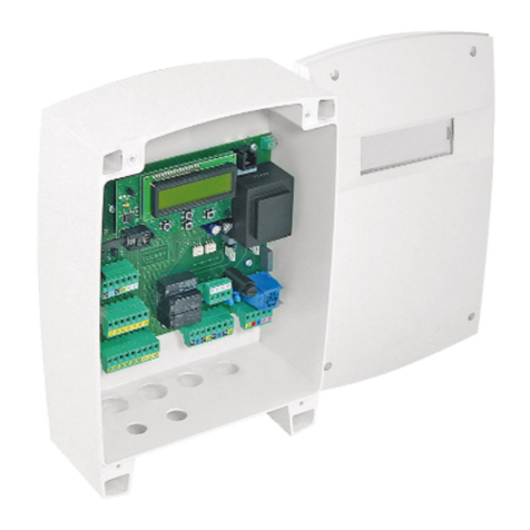
tousek ST 64 User manual

Connection and installation manual
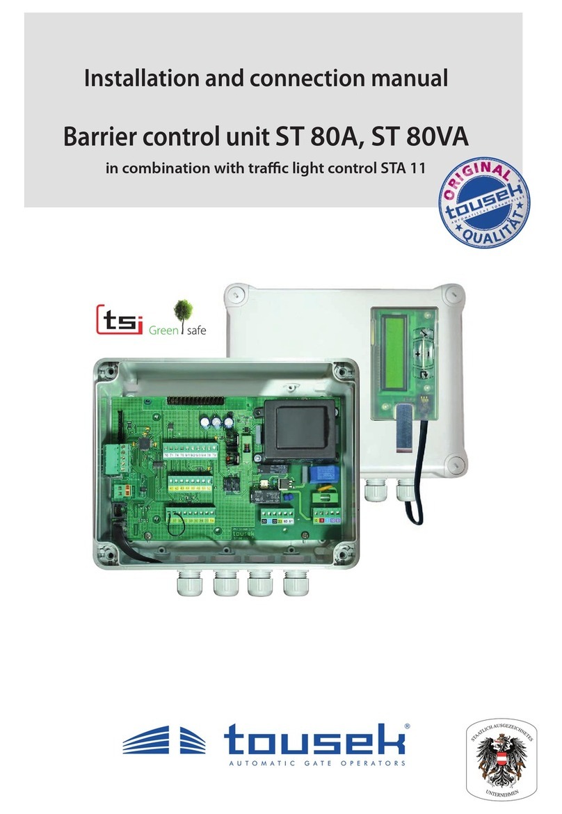
Swing gate control unit ST 64, ST 64A
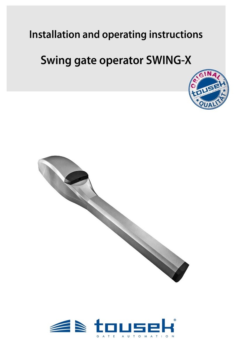
to connect 4 SWING X operators
Safety Sensor

- 2 - tousek / EN_ST-64_02 / 25. 03. 2020
Content
General warning and safety notes.............................................................................................................................. 3
1. General features, control unit overview, technical data............................................................................ 4–6
2. Terminal assignment, connection notes ...................................................................................................... 7
3. Connection notes for SWING X operators ................................................................................................... 8
4. Adjustments - overview, menu structure................................................................................................. 9, 10
5. Connections and adjustments ....................................................................................................................11
Buttons/switches....................................................................................................................................11–12
Safety .................................................................................................................................... 13–16
Left leaf .......................................................................................................................................... 17
Right leaf .......................................................................................................................................... 17
Operating mode.................................................................................................................................... 17, 18
Light / Lamps .......................................................................................................................................... 19
Peripherals .................................................................................................................................... 20–22
Diagnosis .......................................................................................................................................... 23
6. Connection of radio receiver....................................................................................................................... 24
7. Initial operation .................................................................................................................................... 25–28
8. TraclightcontrolboardSTA11........................................................................................................ 29–34
9. Error analysis .......................................................................................................................................... 35
EU - Manufacturer´s Declaration:
ThecompanyTOUSEKGes.m.b.H.,Zetschegasse1,1230Vienna,herebydeclaresthatthecontrolunitST64,ST64A
complies with the following directives:
LowVoltageDirective2014/35/EU,incl.changes.
ElectromagneticCompatibilityDirective2014/30/EU,incl.changes.
Themanufacturerreservestherighttochangespecicationsandfeatureswithoutannouncement.
March 2019
This manual is the sole property of the TOUSEK Ges.m.b.H. and may not be made available to competitors.All rights reserved. No part of it may be reproduced without our prior
written permission. We will not accept liability for any claims resulting from misprints or errors. This edition of the manual replaces all earlier publications of the same.

tousek / EN_ST-64_02 / 25. 03. 2020 - 3 -
General warning and safety notes
• These installation and operating instructions form an integral part of the product “control unit”.Theyhavebeenspeci-
callywrittenforprofessionalinstallerstrainedandskilledinthetradeandshouldbecarefullyreadintheirfulllengthbefore
carrying out the installation. It concerns the control only, not of the overall device “automatic gate”. After the installation
thismanualhastobehandedovertotheuser.
• Installation, connection, adjustments, putting into operation, and servicing may only be carried out by trained
professionals in full accordance with these installation and operating instructions.
• Before carrying out works on the gate system, the power supply has to be turned o.
•Beforetakingothehousingcover,alwaysturnothemainsswitch!
• The EU Machine Directive, laws and rules concerning the prevention of accidents, and laws and standards which are in
forceintheEUandintheindividualcountrieshavetobestrictlyfollowed.
•TheTOUSEKGes.m.b.H.cannotbeheldliableforanyclaimsresultingfromdisregardsofthelawsandstandardsin
force during the installation and operation.
•Thepackagingmaterials(cardboard,plastic,EPSfoampartsandllingmaterialetc.)havetobeproperlydisposedof
inaccordancewiththeapplyingrecyclingandenvironmentalprotectionlaws.Theymaybehazardoustochildrenand
thereforehavetobestoredoutofchildren´sreach.
•Theproductisnotsuitableforinstallationinexplosion-hazardousareas.
•Theproductmayonlybeusedinaccordancewithitsoriginalpurpose,forwhichithasbeenexclusivelydesigned,and
whichisdescribedintheseinstallationandoperatinginstructions.TheTOUSEKGes.m.b.H.rejectsanyliabilityifthe
product is used in any way not fully conforming to its original purpose as stated herein.
• Children have to be instructedthatthegatefacilityaswellasthebelongingpartsmaynotbeusedimproperly,e.g.for
playing.Furthermorehandheldtransmittershavetobekeptinsafeplacesandotherimpulseemittersasbuttonsand
switcheshavetobeinstalledoutofchildren‘sreach..
•Beforebeginningwiththeinstallationtheinstallerhastomakesurethatallmechanicalcomponentsofthegatefacil-
ity,likecarrierprole/rail,gateframeandpanels,guidingelementsetc.aresucientlysupportiveandresistantforthe
purpose of gate automation.
•Allelectricalinstallationshavetobemadeinfullconformitywiththeapplyingrulesandlaws(e.g.usingafaultcurrent
circuitbreaker,propergroundingetc.).
• An all-pole disconnecting main switch with a contact opening-gap of minimum 3 mm has to be foreseen.
• After installation the proper function of the gate facility and the safety devices has to be checked!
•TheTOUSEKGes.m.b.H.rejectsanyliabilityforclaimsresultingfromusageoftheproductincombinationwithcompo-
nents or devices which do not fully conform to the applying safety laws and rules.
•Onlyoriginalspareandreplacementpartsmaybeusedforrepairoftheproduct.
•Theinstallerhastoinformtheuseraboutallaspectsoftheautomaticoperationofthecompletegatefacility,aswellas
aboutemergencyoperation.Theinstallerfurtherhastosupplytotheuserallinstructionsrelatingtothesafeoperation
ofthegatefacility.Theinstallationandoperatinginstructionsalsohavetobehandedovertotheuser.
Maintenance
• Maintenance works may only be carried out by qualied personnel.
• Maintenance and servicing of the complete gate facility has to be carried out according to the gate builder´s/
installer´s instructions.
• Check the proper sensitivity setting of the ARS safety reverse system once a month.

- 4 - tousek / EN_ST-64_02 / 25. 03. 2020
NT
ST SCH
KL2
HS
E
A
KL1
ConnectionatterminalblockKL2:
- motors and motor capacitators
-24Vd.c.supplyforaccessories
components of the control box
ST controlboardselectable:
ST64:withouttraclightoperation
ST 64A:
equippedfortraclightoperationwithSTA11
KL1 terminalblockofcontrolunitboardST
NT powersupply (pre-wired)
SCH contactor1–8(pre-wired)
HS mainswitch (pre-wired)
KL2 terminalblockonDINrail (pre-wired)
positions of the optional components:
A traclightcontrolunitSTA11
E dropboltmodule
MST dropboltcontrolunit(onhousingdoor)
with1or2motorcontrolboardstocontrol
1or2dropboltsSAFELOCK
• suitableforswinggates withelectromechanicaloperators
SWINGX,230V(singleordoubleleaf)withintegratedsensor
• ST64A:traclightoperation(STA11requiredadditionally)
• leafdelayadjustableatopeningandclosing
• automaticclosurewithadjustablepausetime
• traveltimeofbothoperatorswillbeadjustedautomatically
• safetysystemARS(automaticreversalsystem)
• operating mode: impulse, automatic or dead man mode
• integrated evaluation of safety sensing edge
• self-monitoring of photocell
• self-diagnosis display
•
optional:dropboltmoduleandcontrolunit
• slots for optional module and radio receiver
• simple programming via menu navigation
1. General information Swing gate control unit ST 64(A)
Technical data
Swing gate control unit ST 64, ST 64A
power supply 230Va.c.,+/-10%50Hz protection class IP54
motor output 4x500W,230Va.c. speed sensor
ashinglightoutput 230VAC,40W
photocell output 24Va.c.
art. no.
ST 64 12112340
ambienttemperature -20°Cbis+70°C ST 64A 12112430
traclightcontrolboardSTA11
fortrafficlightoperationalreadybuiltintoST64A
optional:
I-loop detector ISD 6
2-channels,pluggableintrafficlightcontrolboardSTA11
art. no.
13430140
dropboltcontrolunit
for1dropbolt:
art. no.
12112410 for2dropbolts:
art. no.
12112420
dropboltSAFELOCK
anthracite grey:
art. no.
11260670
grey aluminium:
art. no.
11260680
further optional components pluggableradioreceiver•
additional module for courtyard/control lamp • additional module for gate
status evaluation • radio transmission system TX 310
Control box

tousek / EN_ST-64_02 / 25. 03. 2020 - 5 -
E
A
MST
dropboltcontrolunitforonedropbolt dropboltcontrolunitfortwodropbolts
Additional components:
trac light control unit (A) for ST64A, optional: dropbolt module (E) and dropbolt control unit (MST)
e.g. ST 64A including additional components:
A traclightcontrolunitSTA11 page 29–34
optional:
E dropboltmodule page 21–22
MST dropboltcontrolunit page 21–22
For wiring the additional components, please follow
the descriptions on the pages listed

- 6 - tousek / EN_ST-64_02 / 25. 03. 2020
FE
–
ESC ENTER
+
Display
T
D
F1
ZM
KL1
E
B
88 89
Attention
During connection,
adjustment and mainte-
nance works please take
care, that the electronic
circuit board won´t be
damaged by moisture
(rain).
Important
The optional „tousek-
connect“ or the „tousek-
service interface“ must
be connected with
socket (D)!Not with (E) !
Control board (ST)
Components of the control board
(KL1)
terminalblocksofthcontrolboard(ST)
(D) display connector
(withprogrammingbuttons+,-,ESC,ENTER)
or
TC/TSI-
connection (optional
„tousek-connect“/
„tousekserviceInterface“)
(E) Systemconnectorforoptionaldropboltmodule
( page 21)
(B) system connector (t.88/89)onlyontheST 64A
(connectionwithtraclightcontrolboardSTA11)
(FE) slot for optional radio receiver (page
24
)
(ZM)
slot for optional module „courtyard/control lamp“
or
„gate
status display
“(page 20)
(T) transformer
(F1) fuse 6,3A F
Danger
• Before connection work or taking o
the control cover, the main switch
must be turned o !
• If the control unit is power supplied, the parts are
under voltage.
• In order to avoid electrical strokes, the safety regula-
tions have to be kept.
• The device may only be connected by trained profes-
sionals.
• Theproductis not suitable for installationin explosion-
hazardous/explosive areas.
• An all-pole disconnecting main switch with a contact
opening gap of min. 3 mm has to be foreseen. The
gate facility has to be secured according to the valid
safety regulations!
• IMPORTANT: The control lines (sensor, buttons, radio,
photocells, etc.) have to be laid separately from the
230V lines (supply line, motors, signal lamp).
Connections
• The wiring to the standard components (switching power supply, contactor 1–8, main switch and the connection to the
terminals on the DIN rail (KL2) are carried out at the factory.
• Connectionworktobecarriedoutisessentiallylimitedtotheterminalstrips(KL1) of the control print, the terminal strip
(KL2)onDINrailfordriveconnectionsandthe24Vd.c.supplyofaccessories( page 7, 8)andnallytheconnection
ofthe230Va.c.supplylineatthemainswitch(HS).
exception:
For the wiring of additional components, please follow the descriptions on the listed pages.
• Connections to motor bolt module and motor bolt control (optional) page 21–22
• Connections to trac light control STA 11 (built into the ST64A) page 29–34

tousek / EN_ST-64_02 / 25. 03. 2020 - 7 -
2. Terminal assignment KL1, KL2 Swing gate control unit ST 64(A)
supply of
photocell transmitter
supply of
photocell receiver
common
PHC-contactinside
PHC-contactoutside
41 42 43 44 45 46 48
trafc light control board page
29
rotational speed sensor +
sensor signal 1 (left leaf)
rotational speed sensor –
rotational speed sensor +
sensor signal 2 (right leaf)
rotational speed sensor –
1
2
3
1
2
3
88 89
connection
tracligthcontrolSTA11
88 89
230Va.c.powersupplyandgrounding
connection on the main switch (HS)
on the DIN rail.
KL2HS
common
STOPP-button
IMPULSE-button
common
CLOSE-button
PEDESTRIANbutton
safety sensing edge 1
safety sensing edge 2
30 31 32 30 33 34 50 52 53
8,2kΩ
8,2kΩ
Motoranschlüsse:
Klemmleiste (KL2)
(aufHutschiene)
20 21 22 23 24 25 26 27
Terminal blocks (KL1) on the control board (ST)
STOPP button
If no stop switch is connected, terminals
30/31havetobewire-bridged.(setat
factory).
Thestop inputhas no emergency
stop function! - In order to
ensure the emergency stop function,
provide the supply line with an all-pole
disconnecting emergency stop switch,
thatlocksafteractuation!
motor connections:
terminalblock(KL2)
(onDINrail)
20 21 22 23 24 25 26 27
80 81 82 83
the impulse inputs (impulse, pedestrian, CLOSE are not active
intraclightoperatingmodewhenusingST 64A!
Connection of the
motor capacitors on the
terminalblock(KL2)
on the DIN rail
terminal block (KL2) on DIN rail
24V.d.c for accessories
+
–
motor capacitator
motor 1 left leaf
grounding
motor capacitator
motor 2 left leaf
grounding
motor capacitator
motor 1 right leaf
grounding
motor capacitator
motor 2 right leaf
grounding
M2RM1RM2LM1L
+- 8081 20 21 22 82 83 24 25 26 80 81 20 2122 82 83 24 25 26
brown
blue or gray
black
brown
blue or gray
black
brown
blue or gray
black
brown
blue or gray
black
ashinglight230Va.c.,
max.40W
Erdung
Versorgungsspannung
230V a.c.
L N
0 12 10 11
power supply connection
on the main switch (HS)
on the DIN rail.

- 8 - tousek / EN_ST-64_02 / 25. 03. 2020
3. Connection notes operator SWING X Swing gate control unit ST 64 (A)
Danger
• Before connection work or taking o the housing cover, the power supply has to be turned o !
• Set force adjustments (menu: left left and right leaf) according to your eective safety rules and regulations
also follow safety instructions on page 6 !
Important: notes for connection and adjustment of operators
• Fourmotors230V(eachmotormax500W)canbeconnectedtotheST64(A).Max.twomotorscanbeinstalledby
stacking them parallely on each leaf dimensions see installation manual of SWING X).
• TheoperatorSWINGXhasaconnectioncableforthepowersupply(markedwithcolour)andfortheintegratedtorque
sensor(markedwithnumbers1–3).Thesensorsignaldenestheperformance/responsewhenhittinganobstacleor
whenreachingagateendposition(adjustmentofsensorsensibilitypleaseseemenu“left(right)leaf”
• Note that after turning on the power supply and giving an impulse the gate leaves are opening.
Ifthisisnotthecasethentheterminals20/22formotor1andtheterminals24/26formotor2havetobeinterchanged.
•IMPORTANT:for operation with one motor/operator please deactivate the other one by choosing “MOTOR OFF” !
The adjustments in the menu LEFT (RIGHT) LEAF/OPERATOR „Motor ON or OFF“ must match the
actual motor connection on the control unit terminals.
CONNECTION of operators to control unit
2 left operators 2 right operators
INSIDE
Connection cable with
colour or number
left operators
to terminal
right operators
to terminal
1. 2. 1. 2.
(M)
motorcable
brown → 20 24 20 24
blue or gray → 21 25 21 25
black → 22 26 22 26
green/yellow → ground terminal
ground terminal
(S)
sensorcable
1 →65 65
2 →66 67
3 →
68 68
if shield →
Motor and sensor wires
• The motor and sensor wires must be supplied to the control unit in 2 separate tubes
or a cable channel with partition.
• The sensor wire must not exceed the max. length of 50m ! - For lengths of more than 20m shielded control
lines must always be used. The shield must be clamped together with the cable number 3 (terminal 68)
• If sensor wires with more than 3 cables are used the remaining cables must be clamped together with the
cable number 3 (terminal 68) - do not clamp to a ground wire (earth lead)!
•
When connecting the sensors to the control unit please note the labeling/marking of the cables (number 1–3).
Bad connection leads to destruction !
2
3
1
yellow/green
black
blue
brown
3
2
1
S
M
IMPORTANT!
separate tubes or a cable
channel with partition!
IMPORTANT: Connect only one sensor cable to the control unit per leaf!!
24V.d.c for accessory
+
–
motor capacitator
motor 1 left leaf
grounding
motor capacitator
motor 2 left leaf
grounding
motor capacitator
motor 1 right leaf
grounding
motor capacitator
motor 2 right leaf
grounding
M2RM1RM2LM1L
+- 8081 20 21 22 82 83 24 25 26 8081 20 21 22 82 83 24 25 26
brown
blue or gray
black
brown
blue or gray
black
brown
blue or gray
black
brown
blue or gray
black
rotational speed sensor +
sensor signal 1 (left leaf)
rotational speed sensor –
rotational speed sensor +
sensor signal 2 (right leaf)
rotational speed sensor –
1
2
3
1
2
3
terminal block KL1
(oncontrolunitboard)
terminal block KL2 (on DIN rail):
IMPORTANT: Connect
only one sensor cable to
the control unit per leaf!

tousek / EN_ST-64_02 / 25. 03. 2020 - 9 -
–
ESC ENTER
+
Display
Programming buttons Einstellungen-Übersicht
• Theadjustment(programming)oftheoperatingparametersiscarriedoutviafourprogrammingbuttonsand
thetextdisplay.
• Beforeyoucanstartprogramming,selectthelanguageofthedisplay.Youcandothisbypressingthe + or -
and choose the language for the menuas and press ENTER.
• Note:Thelanguagesettingcanbechangedanytimebypressingthe ESC button for 5s.
• The text display informs you on the operating modes,
selected menus and adjustment of several parameters.
• Theprogrammingofthecontrolisdonethroughfourbut-
tons (+, -, ENTER and ESC).
• Scrollingthroughthedierentmenupoints(up/down)and
changingaparameter(increase/decrease)isdonewith
buttons + and - .
AUTO-COUNT:Whenabuttonispressedandheld,an
automatic scrolling of the menu (or change of the param-
eter)iscarriedout.
• By pressing the ENTER-button you enter the displayed
menu point or memorise the shown value of a parameter.
• By pressing the ESC-button you return to the superior menu point. Changed adjustments of a parameter are rejected
withthisbutton(theoriginalvalueiskept).
• AUTO-EXIT:Ifduringprogrammingnobuttonisactuatedfor1minuteorlonger,theprogrammingmodeisleftautomati-
cally. The control is set „ready“ without storageofpossiblychangedvalues.
4. Adjustments - overview Swing gate control unit ST 64 (A)
• The programming menu is divided into „BASIC SETTINGS“ and the „MENU CONTROL“.
BASIC SETTINGS
• When programming the control the rst time, you enter the „BASIC SETTINGS“.
• Herethenecessaryadjustmentsforoperationofthegatefacilityaremade.
• Enteringthemenucontrol(forextendedprogramming)ispossiblebyselecting„MENU CONTROL“
MAIN MENU CONTROL
• Thenexttimeyouwilldirectlyenter„MENU CONTROL“.(TheBASICSETTINGSareskipped.)
• Themenucontrolcontainsallpossibleadjustments.
Inthefollowingpagesthesinglemenupointsaremarkedasshownbelow:
=possibleadjustment(orvalueassignment)= factory setting = status display
Gmarks the menu points which are contained in the BASIC SETTINGS
Programming menu Adjustments - Overview

- 10 - tousek / EN_ST-64_02 / 25. 03. 2020
Main layer Sub layer Adjustments
buttons/switches
page 11, 12
Gimpulse button OPEN/STOP/CLOSE
OPEN/CLOSE/OPEN
OPEN
DEAD MAN
*) if impulse button is set
to DEADMAN, then the
pedestrian and close button
are also set automatically to
DEADMAN mode.
(not selectable under „pe-
dest.- button“)
pedestrian button OPEN/STOP/CLOSE
OPEN/CLOSE/OPEN
OPEN
Impulse OPEN
DEAD MAN *)
safety
page 13–16
Ginner photocell active
not active
Gouter photocell active
not active
Gmain safety edge 1 active
not active
radio edge TX310
Gmain safety edge 2 active
not active
radio edge TX310
photocell function inside during closing reverse
stop - after release open
during opening stop - then open
photocell function outside during closing reverse
stop - after release open
PHC-pause time noinuenceofphotocell
abortpausetime
re-start of pause time
immediate close after opening
PHC-self test active
not active
left leaf
page 17
Gmotor motor ON
motor OFF
no left operator:
>MotorOFF!
Gdelay left leaf opening delay
closing delay
Gdelay time left 0...25s = 2s
ARS response time 0,15...0,95s [ increment 0,05 ] = 0,50s
right leaf
page 17
Gmotor motor ON
motor OFF
no right operator:
>MotorOFF!
Gdelay right leaf opening delay
closing delay
Gdelay time right 0...25s = 2s
ARS response time 0,15...0,95s [ increment: 0,05 ] = 0,50s
operating mode
page 17, 18
impulse logic stop, start of pause time
impulse suppression when opening
pausetimeextension
Goperating mode impulse mode
automatic 1...255s [increment: 1]
partial opening 25...100% =100%
automatic mode complete/partial opening
only complete opening
only partial opening
pause time logic noinuence
permanent open in automatic mode
closing edges left/right
inside/outside
limit tolerance 3...20 = 20
lights/lamps
page 19
prewarning OPEN OFF, 1...30s = OFF
prewarning CLOSE OFF, 1...30s = OFF
Green phase
only with ST 64A
(+ STA 11)
5...120s [ increment 1 ] = 20s
Clearance time 1...60s [ increment 1 ] = 5s
Trac light gate
CLOSED
OFF
constant red
Trac light logic bothsidegreen
one side green
courtyard lamp 1 OFF, 5...950 = OFF
control lamp 1 illuminates during open and close
blinksslowly/illuminates/blinks
illuminates in open position
peripherals
page 20–22
electric lock switchedo
1...10s
visibleonly
if activated under „locking“
reverse stroke
reverse stroke only with active locking!
nicht aktiv
0,5...8s
additional module courtyard/control lamp
status display 1
status display 2
locking e-lock/magnetic clamp
motor lock
motor lock OPEN and CLOSE
only OPEN
only CLOSE
visibleonly
if activated under „locking“
diagnosis
page 23
status display status display
delete position NO
YES
factory setting NO
YES
software version show software version
serial number showserialnumber
1) The menu points courtyard lamp and control lamp will only appear on display if in menu
„Additional module“ courtyard lamp/control lamp is selected.
Swing gate control unit ST64(A)
+
–
Menu structure Adjustment - overview
ESC ENTER
Note: some adjustments regarding function or operating logic can only be executed if barrier is closed and if the display shows „ready“.
-optionsonlyselectablewithST64A(traclightcontrolunit)
-optionsonlyselectablewithST64
-unmarkedoptionsselectablewithST64andST64A
tousek / EN_ST-64_02 / 25. 03. 2020 - 11 -
• AgeneralstatusdisplayofallinputsisavailableinmenuDIAGNOSIS/STATUSDISPLAY.
5. Connections and adjustments ST 64 (A)
Thesinglemenupointsaremarkedasshownbelow:
=possibleadjustment(orvalueassignment)= factory setting = status display
Gmarks the menu points which are contained in the BASIC SETTINGS
Pushbuttons,keyswitchesorexternalradioreceiverswithpotential-freenormallyopencontactscanbeusedas
impulse,pedestrianandCLOSEswitches.TheSTOPterminalsrequireanormallyclosedcontactsswitch!
In trac light mode the impulse-, pedestrian-, close buttons are without any function.
GImpulse button (terminalsKL130/32) Buttons/switches
OPEN/STOP/CLOSE successive impulses(factorysetting):animpulseoftheimpulseswitchmakesthemotorstart
opening/closing. If the impulse switch is actuated again during this opening-/closing movement, the motor stops.
Withthenextcommandoftheimpulseswitchthemotormovesintheoppositedirectionofthelastgatemovement
OPEN/CLOSE/OPEN successive impulses:
an impulse of the impulse switch makes the motor start opening/closing.
If the impulse switch is actuated again during this opening/closing movement, the travel direction is reversed.
•In this operation mode it is not possible to stop the motor with the impulse switch – it always
moves until reaching an end position. (Opened or closed position).
• for the function OPEN/CLOSE/OPEN we strongly suggest the installation of a photocell!
OPEN: Onlyopeningcommandsareacceptedbytheimpulseswitch–closingthegatewiththeimpulseswitchis
notpossible..
DEAD MAN: Themotoropensaslongastheimpulseswitchispressed(hold)–closingthegatewiththeimpulse
switchisnotpossible.Assoonastheswitchisreleased,themotorstops.If hold to run operating mode is selected,
the radio receiver slot (FE) is set out of order for reasons of safety.
• IftheimpulseswitchissettoDEADMANoperation,thenalsoallotherbuttonsareinDEADMANmode.
Withtheimpulse-,orthepedestrianbuttonthegateisopened,withtheCLOSE-buttonitisclosed.
• IMPORTANT: Do not put into operation in dead man mode.
Select only after putting into operation (page 25), if desired.
buttons/switches Connections and adjustments
Danger
• Before connection works or taking o the housing cover the power supply has to be turned o !
• Follow safety instructions! ( page 6)

- 12 - tousek / EN_ST-64_02 / 25. 03. 2020
Pedestrian button (terminalsKL130/34) Buttons/switches
OPEN/STOP/CLOSE successive impulses:
Animpulseofthepedestrianbuttonmakestheaccordinggateleafopen/close.Ifthepedestrianbuttonisactuated
againduringthismovement,themotorstops.Withthenextimpulsethemotormovesinoppositedirectionofthelast
gate movement.
OPEN/CLOSE/OPEN successive impulses:
Acommandofthepedestrianbuttonmakestheaccordinggatewingopen/close.Ifthebuttonisactuatedagainduring
this movement, the travel direction is reversed.
•In this operation mode it is not possible to stop the motor with the pedestrian button – it always
moves until reaching an end position. (Opened or closed position).
• for the function OPEN/CLOSE/OPEN we strongly suggest the installation of a photocell!
OPEN: Onlyopeningcommandsareacceptedbythepedestrianbutton–closingthegatewiththepedestrianbutton
isnotpossible.
Impulse OPEN:
Theterminals30/34havethexfunctionofanadditionalimpulseswitch,whichcanonlyopenthegate.
A command with the pedestrian button effects a complete opening of both leaves when the ad-
justment “Impulse OPEN” is selected.
DEADMAN: The motor opens as long as the pedestrian button is pressed (hold) – closing the
gate with the pedestrian button is not possible. As soon as the button is released, the motor stops.
If hold to run operating mode is selected, the radio receiver slot (FE) is set out of order for reasons of safety.
The DEADMAN function can not be chosen actively but is set automatically as soon as the impulse
button is set to DEADMAN mode.
CLOSE-button (N.O.contact,terminalsKL130/33) Buttons / switches
• A command with the CLOSE-switch engages closing of gate. In deadman mode the gate closes as long as
the CLOSE-switch is pressed/switched. As soon as switch is released the gate movement stops.
STOPP-switch (N.C.contact,terminalsKL130/31) Buttons / switches
• when pressing the stop switch the gate stops in any desired position.
As stop switch a break contact has to be used.
If no stop switch is connected, terminals 30/31 have to be wire-bridged. KL1 31
30
The stop input has no emergency stop function! - In order to ensure the emergency stop function, provide
the supply line with an all-pole disconnecting emergency stop switch, that locks after actuation!

tousek / EN_ST-64_02 / 25. 03. 2020 - 13 -
Ginner photocell (contact:terminalsKL145/46) Safety
active: tobeselected,ifinnerphotocellshouldbetriggered.
not active: tobeselected,ifinnerphotocellshouldnotbetriggered.
Safety Connections and adjustments
Gouter photocell (contact:terminalsKL145/48) Safety
active: tobeselected,ifouterphotocellshouldbetriggered.
not active: tobeselected,ifouterphotocellshouldnotbetriggered.
Important: notes for photocells
Photocell connection:
• The control unit has a power supply connection for a
24V a.c.photocell(PHC)
power supply: PHC-transmitter: terminals KL1 41/42
PHC-receiver: terminals KL1 43/44
Note:in„gateclosed“positiontheterminals41/42arebeingswitched
intoenergysavingmode(nocurrent)(onlyiftheradiotransmission
systemTX310isnotused)!
• Atsuppliedandpositionedphotocellsthecontacthastobeclosed.
PHCcontacts: inside = term. KL1 45/46, outside = term. KL1 45/48,
back area =Withadditionalinnerphotocellsthebackareaofthegate
canbemonitored.(Allinnerphotocellsarethensetinseriesatcontrol
terminals45/46(terminalsforinnerphotocells).
Mounting notes (SYNC function):
IMPORTANT: When using two pairs of photocells please do not install
bothphotocelltransmitters/receiversonthesameside(toeleminate
interferencebetweenboth)!
Exception: photocells with SYNC function allow the installation of
bothphotocelltransmitters/receiversonthesamesidewithoutcausing
interference to each other.
Self-monitoring of photocells:
Thecontrolunithasamonitoringfunctionfortheconnectedphotocells.Atestwillbetriggeredbyeachimpulseandwillbe
checked if the receiver of the photocell responds to the signal from the photocell transmitter.
If there is no communication
betweenthephotocellreceiverandtransmitterthecontrolunitrespondswithanerror.
The deactivation of the self-test function is only permitted if the safety installations correspond to the
category 3 !
Photocell functions:
Theexactfunctionofthephotocellsdependsontheprogrammingofthecontrolunit:
see menu point SAFETY/inner (outer) photocell function, resp. photocell with pause time ( page 16).
Detailed information you will nd in the corresponding photocell manual.
1
2
3 3
left right
INSIDE
(1) inner photocell
(2) outer photocell
(3)backareaphotocell
Standard
transmitter 1 receiver 1
receiver 2 transmitter 2
mit SYNC
ransmitter 1 receiver 1
ransmitter 2 receiver 2
INNER AND OUTER PHOTOCELL Safety

- 14 - tousek / EN_ST-64_02 / 25. 03. 2020
Important
• To activate the SYNC-function, the
plug-in bridges (J) in both photocell
transmitters have to be removed.
(see manual LS 180).
SYNC
J
Outer photocell
Tousek LS 180 as safety device
Outer and inner photocell
Tousek LS 180 as safety device
transmitter receiver
OUTSIDE:
INSIDE:
transmitter receiver
with active SYNC-function
Photocells - connection examples
Important
• Jumper J of transmitter and receiver has to be
adjusted in the same way.
Outer photocell
Tousek LS 26 as safety device
Outer reective photocell
Tousek RLS 620 as safety device
N.O.
COM
N.C.
48
46
45
44
43
42
41
KL1
N.O.
COM
N.C.
N.O.
COM
N.C.
48
46
45
44
43
42
41
KL1
+
~
-
~
12/24V
J
+
~
-
~
12/24V
NC C NO J
transmitter receiver
48
46
45
44
43
42
41
KL1
24Va.c.
12–240V
a.c./d.c.
48
46
45
44
43
42
41
KL1

tousek / EN_ST-64_02 / 25. 03. 2020 - 15 -
Safety sensing edges Safety
•
Connection and detailed information of radio transmission system TX 310 see according manual.
Gmain safety edge 1 (terminalsKL150/52) Safety
active: tobeselectedifthecontactstrip(8,2kOhm)ofmainsafetysensingedge1shouldbeevaluated.
not active: tobeselectedifthecontactstripofmainsafetysensingedge1shouldnotbeevaluated
radio edge TX310: tobeselectedifsafetysensingedge(8,2kΩ)ofmainentranceedge1shouldbeevaluatedwith
the radio transmission system TX 310.
Gmain safety edge 2 (terminalsKL150/53) Safety
active: tobeselectedifthecontactstrip(8,2kOhm)ofmainsafetysensingedge2shouldbeevaluated.
not active: tobeselectedifthecontactstripofmainsafetysensingedge2shouldnotbeevaluated
radio edge TX310: tobeselectedifsafetysensingedge(8,2kΩ)ofmainentranceedge2shouldbeevaluatedwith
the radio transmission system TX 310.
Safety sensing edges (main closing edge 1 + 2)
• OBSTACLE DETECTION: when a contact strip/safety edge is triggered/activated then a change of direction is
eectedfor1second.Thenthegatestops.
• The activation of the safety sensing edges is made in menu „Safety / main closing edge 1“ (term. 50/52) and
„Safety / main closing edge 2“(term.50/53)
• If in the menu item „operating logic / closing edge“
(page18)oneofthemodes„left / right“ or „inside
/ outside“ is selected - this results in the wiring of the
safety contact edges to make with each other and the
connection to the control terminals.
Safety sensing edges in mode „left/right“,thatshouldreactonanobstacleattheleft(right)leaf,haveto
beconnected(serially)totheconnectionclampsofthemainclosingedge1(2).
Safety sensing edges in mode
„inside/outside“, which should react
onanobstacleattheinner
(outer)
side of the leaf,
beconnected(serially)totheconnectionclampsofthemainclosingedge1(2)
Example: W 8,2kΩ nal resistance
E nal edge
D passage edge
S to the control board
When connecting one safety edge a nal edge (E) has to be used.
E
W
D D S
50
52
50
53
main closing edge 1
main closing edge 2
Important
• After giving the impulse to program the end positions, no other impulse must be given. Also the safety devices
mustn´t be triggered. This would lead to an interruption of the programming process.
• Therefore, the mechanical stops must be set so that the existing contact strips cannot be triggered.
main closing edge 2
(right leaf or outside)
main closing edge 1
(right leaf or outside)
8,2kΩ
8,2kΩ
53
52
50
KL1

- 16 - tousek / EN_ST-64_02 / 25. 03. 2020
Photocell function inside Safety
during closing reverse: aninterruptionofthephotocellduringclosingmakesthegatereverse(open).Inautomatic
mode the gate closes as soon as the pause time has run out. In impulse operation another closing command has to
begiven.
stop - after release open: aninterruptionofthephotocellbeamduringopeningorclosingmakesthemotorstopas
long as the photocell stays interrupted. After release of the photocell, the gate opens. In automatic mode the gate closes
assoonasthepausetimehasrunout,inimpulseoperationanotherclosingcommandhastobegiven.
during opening stop - then open: an interruption of the photocell during opening makes the motor stop as long as
the photocell stays interrupted. After release of the photocell, the gate opens (backareamonitoring).Inautomaticmode
thegateclosesassoonasthepausetimehasrunout,inimpulseoperationanotherclosingcommandhastobegiven.
Photocell function outside Safety
during closing reverse: aninterruptionofthephotocellduringclosingmakesthegatereverse(open).Inautomatic
mode the gate closes as soon as the pause time has run out. In impulse operation another closing command has to
begiven.
stop - after release open: aninterruptionofthephotocellbeamduringopeningorclosingmakesthemotorstopas
long as the photocell stays interrupted. After release of the photocell, the gate opens. In automatic mode the gate closes
assoonasthepausetimehasrunout,inimpulseoperationanotherclosingcommandhastobegiven.
PHC-pause time Safety
no inuence of photocell: thephotocelldoesn’thaveanyinuenceonthepausetimeinautomaticmode.
abort pause time: in automatic mode an interruption of the outer photocell during pause time shortens the pause time.
After release of the photocell the gate starts closing.
re-start of pause time: in automatic mode an interruption of the outer photocell during pause time, restarts the pause
time. As soon as the pause time has run out, the gate closes.
immediate close after opening: If the outer or inner photocell is interrupted during the opening movement or if the
outerphotocellisinterruptedinopenposition,thenthegatebeginstocloseafterthereleaseofthephotocell.
PHC-self test Safety
active: photocellself-testisexecutedwithanopeningimpulse(switch,button)ingateposition„closed“.
not active: photocellself-testisnotexecuted
Attention
• The photocell self-test can only be deactivated by selecting „not active“.
• The deactivation of the self-test function is only permitted if the safety installations correspond to the
category 3 !
PHOTOCELL FUNCTIONS Safety

tousek / EN_ST-64_02 / 25. 03. 2020 - 17 -
GMotor
(Supply: term. KL2 20/21/22, grounding: 23 - Sensor: term. KL165,66,68)
Left leaf
MOTOR ON
MOTOR OFF left motors INSIDE
If a left operator is not available then set
here to „MOTOR OFF“!
GDelay left leaf Left leaf
OPENING DELAY: the left leaf opens after the adjusted delay time.
CLOSING DELAY: the left leaf closes after the adjusted delay time.
GDelay time left 2s (factory setting) Left leaf
0–25s time delay adjustable: indicates the delay time at opening or closing.
ARS response time 0,50 (factory setting) Left leaf
0,15–0,95 adjustable: indicates the response of the Automatic Rerversal System.
GMotor
(Supply: term. KL2 24/25/26, grounding: 27 - Sensor: term. KL165,67,68)
Right leaf
MOTOR ON
MOTOR OFF right motors
INSIDE
If a right operator is not available then
set here to „MOTOR OFF“!
GDelay right leaf Right leaf
OPENING DELAY: the right leaf opens after the adjusted delay time.
CLOSING DELAY: the right leaf closes after the adjusted delay time.
GDelay time right 2s (factory setting) Right leaf
0–25s time delay adjustable: indicates the delay time at opening or closing.
ARS response time 0,50 (factory setting) Right leaf
0,15–0,95 adjustable: indicates the response of the Automatic Rerversal System.
Right leaf Connections and adjustments
Left leaf Connections and adjustments
Important
• FourSWINGXoperatorscanbeconnectedtothecontrolunitST64(A)(max.twooperatorsperleafinstalledbystacking
them parallely, dimensions see installation manual SWING X).
Operating mode Connections and adjustments
Impulse logic Operating mode
stop, start of pause time: a command of the impulse switch during the opening movement stops the gate and starts
the pause time in automatic operation – as soon as the pause time has run out, the gate closes automatically.
impulse suppression when opening: commands which are emitted during the opening movement are suppressed.
Commands during closing are accepted.
pause time extension: an impulse in automatic operation restarts the pause time. If this menu point is chosen, the
impulse suppression during opening is active at the same time.
GOperating mode Operating mode
impulse mode: for initiating the closing movement, an impulse is necessary.
automatic closing, pause time adjustable from 1-255s: gate closes as soon as the adjusted pause time has run out.
Partial opening 100% (factory setting) Operating mode
25–100% adjustable: indicates the partial opening of the gate leaf with closing delay in relation to complete opening
width.
This adjustment is ONLY adopted in CLOSED Postion.

- 18 - tousek / EN_ST-64_02 / 25. 03. 2020
Automatic mode Operating logic
complete/partial opening: either with complete as well as partial opening, the gate closes automatically after the
adjusted pause time.
only complete opening: only after complete opening, the gate closes automatically after the adjusted pause time.
only partial opening: only after partial opening the gate closes automatically after the the adjusted pause time.
Pa Pause time logic Operating logic
no inuence
permanent open in automatic mode: if this function is activated, the control unit goes from automatic mode into impulse
mode with activated pause time through impulse in open gate position for this cycle , hence if gate is open then an
impulsewillendtheautomaticmode-thegateremainsopen.Onlythenextimpulsewillclosethegateandthecontrolunit
goesbacktoautomaticmode.Withthisfunctione.g.theentrancetoacompanysitecanremainopenduringtheday(1st
impulseingateopenposition)andclosedintheevening(2ndimpulse).Thecontrolboardswitchesbacktoautomaticmode
(autom.openingandclosingofgate).
Ifthegateisinpartialopenpositionand„permanentopeninautomaticmode“isselected,soitispossibletoadjust
permanentpartialopenforthiscyclebygivinganimpulseviapedestrian button.Permanentpartialopencanbe
nishedanalogoustotheabovedescribedmethod.
Closing edges (HSK1:terminalsKL150/52,HSK2:terminalsKL150/53) Operating logic
left/right: thesafetysensingedges(contactstrips)can
actuateineverygatemovement(OPEN/CLOSE).
Thesafetysensingedgesfortheleftgateleafneedtobe
connected(inseries)totheterminals 50/52.
The safety sensing edges for the right gate leaf need to
beconnected(inseries)totheterminals 50/53.
inside/outside:
sensing edges at the interior of the gate (terminal 50/52) can only actuate during opening movement and sensing
edges on the outside of the gate (terminal 50/53) only during closing movement.
IMPORTANT ! ASSIGNMENT AND RESPONSE OF SAFETY EDGES
Movement
Assignment
Open Close Examples: (D) passage edge, (E) nal edge
left (HSK 1 - Kl.50/52) right (HSK 2 - Kl.50/53)
D
E
D
E
outside (HSK 2-term.50/53)
D
E
inside (HSK 1-term.50/52)
D
E
HSK1
Mode
left/right
left active active
HSK2 right active active
HSK1
Mode
inside/outside
inside active
HSK2 outside active
Limit tolerance 20 (factory setting) Operating logic
3–20 adjustable:indicatesthetoleranceintheendpositions(lowvalue=sensitivebehaviour).
main closing edge 2
(right leaf or outside)
main closing edge 1
(right leaf or outside)
8,2kΩ
8,2kΩ
53
52
50
KL1

tousek / EN_ST-64_02 / 25. 03. 2020 - 19 -
Warning
•
Before taking o the housing cover the
main switch has to be turned o !
• Follow safety instructions ( page 6) !
Important: Notes regarding
connection of a ashing light
• Attention: Before carrying out
connection works, the power
supply of the facility has to be
turned o
• Aashinglightwith230V,max.
40W can be connected at the
terminals 10/11.
Prewarning OPEN (terminalsKL110/11) Light / Lamps
OFF
1–30s adjustable:beforeeachopeningmovementtheashinglightisactivatedfortheadjustedtime.
Prewarning CLOSE (terminalsKL110/11) Light / Lamps
OFF
1–30s adjustable: before each closing movement the flashing light is activated for the adjusted time.
The following options, marked with in the menu are only valid for ST 64Aincombinationwiththetraffic
light control unit STA 11.
Green phase 20s (factory setting) Light / Lamps
5–120s adjustable [increment: 1]: duration of green phase.
Clearance time 5s (factory setting) Light / Lamps
1–60s adjustable [increment: 1]:timetoleavethetraclightintermediatearea.
Trac light gate CLOSED Light / Lamps
OFF: redtraclightdoesnotilluminateinclosedposition.
Constant red:redtraclightilluminatesalsoinclosedposition.
Trac light logic Light / Lamps
both sides green: bothtraclightsilluminateinopenpositionGREEN,regardlessofwhichsidehasbeengiventhe
green request.
one side green: onlythetraclightilluminatesinopenpositionGREEN,fromthesidefromwherethegreenrequest
hasbeenrequested.
Thefollowingtwomenupointscanonlybeselectedifthemenupointadditionalmenuisadjustedto„Courtyard-/Control
lamp“(henceshownondisplay).
Courtyard lamp (Description add. modules page
20
)Light / Lamps
OFF
5–950 adjustable:atthecourtyardlampoutputanexternallampcanbeconnected(e.g.gardenlamp),whichcanbe
turned on for each opening command for the duration of adjusted time.
Control lamp (Description add. modules page
20
)Light / Lamps
illuminates during open and close: The pilot lamp output is activated during opening- and closing movement.
blinks slowly/illuminates/blinks:Thepilotlampoutputisactivatedasfollows:Duringopeningthepilotlampashes
slowly. During pause time, in opened position or when the gate stops it is illuminated. During the closing movement
itashesrapidly.Ifthegateisclosed,thepilotlampexpires
illuminates in open position: Pilot lamp is illuminated as soon as the gate has reached end position open.
Light / Lamps Connections and adjustments
11
10
KL1

- 20 - tousek / EN_ST-64_02 / 25. 03. 2020
Electric lock Peripherals
switched o
1–10s adjustable:Theelectriclockisactivatedbypushbuttonimpulseorimpulsefrompedestrianbuttonfora
period of time set here to ensure the release depending on the gate situation
Reverse stroke (onlywithactivatedlocking!) Peripherals
switched o
0,5–8s adjustable: Onlywithactivatedlock(electriclockormotorizedlockingbar):Afteranimpulseisgiven,ashort
closingmovementforunlocking(forexample,theE-lock)isinitiatedrst,theunlockingisperformedandthedooris
opening.Withanelectriclock,thereversalstrokeisonlycarriedoutintheopeningdirection.Withamotorbolt,depend-
ingonthesetting,itispossibletosetthereversalstrokealsointheclosingmovement.
Additional module Peripherals
courtyard/control lamp: the menu points courtyard lamp and control lamp are ready for adjustment (that means if not
selected,thesemenupointswillnotbeshownonthedisplay)
status display 1: with the two potential-free signal contacts K1 and K2, the gate end positions (limits) can be
evaluated.
status display 2: with the two potential-free signal contacts K1 and K2, the gate end positions (limits), the gate
movementaswellasagatestopoutsideoftheendpositionscanbeevaluated.
Additional module (optional)
• turn o power supply before installing the additional module!
• Depending on which device, e.g. a courtyard-/Control lamp is
chosen or evaluation of gate statusshouldbeeected,thecorresponding
module (Z)hastobepluggedtotheaccordingslot/plug(ZM)ofcontrolboard.
• Additionallythecorrespondingvaluehastobeselectedinmenupoint
„Additional module“.
Additional module
Courtyard lamp/
Control lamp
• On the terminals 12/13
acourtyardlamp(H)
canbeconnected:
230V, max. 100W
• On the terminals 70/71
acontrollamp(K)can
beconnected:
24Vd.c., max. 2W
1213 7071
L N
HK
– +
Additional module
Gate status display
• with potential free signal contacts K1 (Kl.
90/91)andK2(Kl.92/93)thegatestaturs
canbeevaluatedintwoways(seemenu
point„Additionalmodule“).
• Contact load: 24Va.c./d.c., max. 10W
Function K1 K2
Gate status display
1Gate in CLOSE-Position 1 0
Gate in OPEN-Position 0 1
2
Gate in CLOSE-Position 0 0
Gate opens or closes 0 1
Gate stopped or fault
(Gatenotinendposition) 1 0
Gate in OPEN-position 1 1
signal contacts: 0 = open, 1= closed
9091 9293
signal contacts
K1 K2
ZM
Z
ZM
ST 61
Locking Peripherals
e-lock/magnetic clamp: with additional module electric lock/magnetic clamp.
motor lock:withadditionalmodulemotorizedlockingbar.
Motor lock Peripherals
OPEN and CLOSE:lockingviamotorizedlockingbarinbothendpositionsofthegate.
only OPEN: lockingviamotorizedlockingbaronlyinopenposition.
only CLOSE: lockingviamotorizedlockingbaronlyinclosedposition.
Peripherals Connections and adjustments
This manual suits for next models
1
Table of contents
Other tousek Gate Opener manuals

tousek
tousek TURN 10 User manual

tousek
tousek TPS 6speed User manual

tousek
tousek REX Force Technical document

tousek
tousek FOLD 330/L User manual

tousek
tousek ST 80A Guide

tousek
tousek TPS 60 PRO m6 User manual

tousek
tousek ST 61A User manual

tousek
tousek ST 63 User manual

tousek
tousek SWING 225 AEB/29 N User manual

tousek
tousek Rollco LWA 115/1A User manual