tousek PULL T8 User manual

Mounting and installation manual
Sliding gate operators
PULL T5, -T8, -T10
C
O
M
P
A
T
I
B
L
E

- 2 - tousek / E_PULL-T5-T8-T10_49002305 / 19. 12. 2013
Index
General warning and safety details.............................................................................................................. 3
1. Notes, general characteristics, function, technical data............................................................................ 4
2. Mounting ........................................................................................................................................................ 5
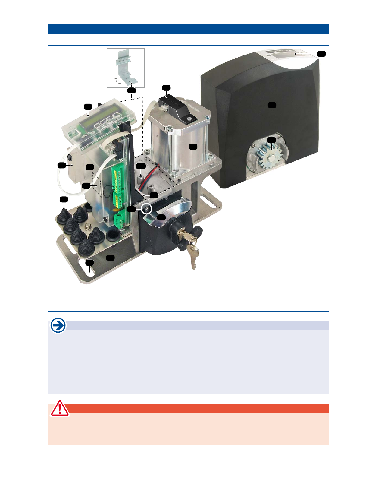
Technical layout PULL T5, -T8, -T10, general mounting notes, warning note............................................ 5
2.1 Mounting of the motor................................................................................................................................. 6
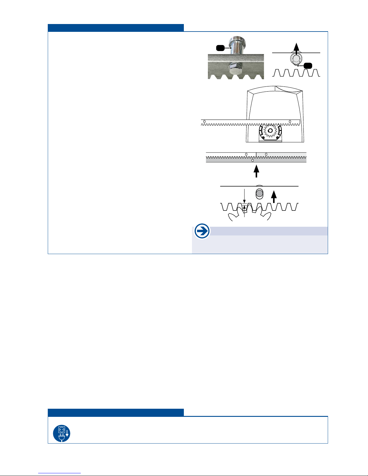
2.2 Mounting of the gear rack........................................................................................................................... 7
2.3 Dismantling................................................................................................................................................. 7
3. Control unit, overview.................................................................................................................................... 8
Warnings - connection works ....................................................................................................................... 9
3.1 Clamp/terminal assignment ....................................................................................................................... 9
3.2 Adjustments - overview, .......................................................................................................................... 10
Programming keys, program menu, basic settings .................................................................................. 10
Structure of the menu............................................................................................................................... 11
3.3 Connections and adjustments ................................................................................................................... 12
Switches/buttons
........................................................................................................................................... 12
Impulse switch (terminals 30/32)............................................................................................................. 12
Pedestrian switch (terminals 30/34) ........................................................................................................ 13
CLOSE switch (terminals 30/33) ............................................................................................................. 13
STOP switch (terminals 31/37)................................................................................................................ 13
Safety ...................................................................................................................................................... 14
GPhotocell (Contact: terminals 45/46) ........................................................................................................ 14
Photocells - connection examples ........................................................................................................... 14
Information for safety edges .................................................................................................................... 16
GMain safety sensing edge (terminals 50/52)............................................................................................ 16
GSide safety sensing edge (terminals 50/51) ............................................................................................ 16
Photocell function ..................................................................................................................................... 17
Photocell with pause time......................................................................................................................... 17
Photocell test............................................................................................................................................ 17
Motor ...................................................................................................................................................... 18
max. force................................................................................................................................................. 18
ARS response time................................................................................................................................... 18
Speed ...................................................................................................................................................... 18
Soft stop way............................................................................................................................................ 18
Soft stop speed......................................................................................................................................... 18
End position OPEN, end position CLOSE................................................................................................ 18
Operating logic............................................................................................................................................. 19
Impulse button.......................................................................................................................................... 19
GOpening direction ..................................................................................................................................... 19
GOperating mode........................................................................................................................................ 19
Partial opening.......................................................................................................................................... 19
Automatic mode........................................................................................................................................ 19
Pause time logic ....................................................................................................................................... 19
Lamps / Lights.............................................................................................................................................. 20
Prewarning OPEN (signal lamp: terminals 10/11) ................................................................................... 20
Prewarning CLOSE (signal lamp: terminals 10/11) ................................................................................. 20
Additional module..................................................................................................................................... 20
Courtyard lamp......................................................................................................................................... 20
Control lamp ............................................................................................................................................. 20
Description of add. modules courtyard lamp/control lamp hence gate status display.............................. 21
Diagnosis ...................................................................................................................................................... 22
Status display ........................................................................................................................................... 22
Delete end positions................................................................................................................................. 22
Factory setting.......................................................................................................................................... 22
Software version....................................................................................................................................... 22
Serial number ........................................................................................................................................... 22
Protocoll.................................................................................................................................................... 22
Status Sensor........................................................................................................................................... 22
4. Emergency release in case of power failure (note for the user) ............................................................. 23
5. Change of euro standard cylinder ............................................................................................................. 23
6. Connection of radio receiver and transmitter button assignment ......................................................... 24
7. Initial operation ...................................................................................................................................... 26, 27
8. Error diagnosis............................................................................................................................................. 28
9. Cable plan ..................................................................................................................................................... 29
10. Dimensioned drawing ................................................................................................................................. 30
This manual is the sole property of the TOUSEK Ges.m.b.H. and may not be made available to competitors. All rights reserved. No part of it may be reproduced without our prior
written permission. We will not accept liability for any claims resulting from misprints or errors. This edition of the manual replaces all earlier publications of the same.

tousek / E_PULL-T5-T8-T10_49002305 / 19. 12. 2013 - 3 -
EU - Manufacturer´s Declaration according Machine Directive 2006/42/EC:
The company TOUSEK Ges.m.b.H., based in Zetschegasse 1, A-1230 Vienna/Austria, hereby declares that the “Sliding
gate operator PULL T5, T8 and T10 is made available only for the purpose of being built into a machine or of being joined
with other machines or machine components, and that it may not be put into operation until a declaration of conformity
according to the Directive 2006/42/EC has been issued for the whole machine.
The following directives and standards have been applied:
- Low Voltage Directive 2006/95/EC, incl. changes
- Electromagnetic Compatibility Directive 2004/108/EC, incl. changes
January 2012
GENERAL WARNING AND SAFETY NOTES
• These installation and operating instructions form an integral part of the product “sliding gate operator”. They have been
specically written for professional installers trained and skilled in the trade and should be carefully read in their full length
before carrying out the installation. They describe the proper installation and operation of the sliding gate operator only,
not of the overall device “automatic gate”. After the installation this manual has to be handed over to the user.
• Installation, connection, adjustments, putting into operation, and servicing may only be carried out by trained profession-
als in full accordance with these installation- and operating instructions.
• Before carrying out works at the gate-system, the power supply has to be turned off.
• The EU Machine Directive, laws and rules concerning the prevention of accidents, and laws and standards which are in
force in the EU and in the individual countries have to be strictly followed.
• The TOUSEK Ges.m.b.H. cannot be held liable for any claims resulting from disregards of the laws and standards in
force during the installation and operation.
• The packaging materials (cardboard, plastic, EPS foam parts and lling material etc.) have to be properly disposed of
in accordance with the applying recycling- and environmental procection laws. They may be hazardous to children and
therefore have to be stored out of children´s reach.
• The product is not suitable for installation in explosion-hazardous areas.
• The product may only be used in accordance with its original purpose, for which it has been exclusively designed, and
which is described in these installation and operating instructions. The TOUSEK Ges.m.b.H. rejects any liability if the
product is used in any way not fully conforming to its original purpose as stated herein.
• Children have to be instructed, that the gate facility as well as the belonging parts may not be used improperly, e.g. for
playing. Furthermore handheld transmitters have to be kept in safe places and other impulse emitters as buttons and
switches have to be installed out of children‘s reach.
• Before beginning with the installation the installer has to make sure that all mechanical components of the gate facil-
ity, like carrier prole/rail, gate frame and panels, guiding elements etc. are sufciently supportive and resistant for the
purpose of gate automation.
• All electrical installations have to be made in full conformity with the applying rules and laws (e.g. using a fault current
circuit breaker, proper grounding etc.).
• An all-pole disconnecting main switch with a contact opening-gap of minimum 3 mm has to be foreseen.
• The electric motor heats up during operation. Therefore the device should only be touched after it has cooled off.
• After installation the proper function of the gate facility and the safety devices has to be checked!
• The TOUSEK Ges.m.b.H. rejects any liability for claims resulting from usage of the product in combination with compo-
nents or devices which do not fully conform to the applying safety laws and rules.
• Only original spare- and replacement parts may be used for repair of the product.
• The installer has to inform the user about all aspects of the automatic operation of the complete gate facility, as well as
about emergency operation. The installer further has to supply to the user all instructions relating to the safe operation
of the gate facility. The installation and operating instructions also have to be handed over to the user.
• Please notice that the warranty will not be applicable if the label with the engine number has been removed or
damaged.
Maintenance
• Maintenance works may only be carried out by qualied personnel.
• Check the proper sensitivity setting of the ARS safety reverse system once a month.
• Check the proper function of the emergency release mechanism periodically.
• Check if all mounting screws are securely fastened periodically.
• Remove dirt deposits from the operator and gear rack periodically.
• Maintenance and servicing of the complete gate facility has to be carried out according to the gate builder´s/
installer´s instructions.

- 4 - tousek / E_PULL-T5-T8-T10_49002305 / 19. 12. 2013
Characteristics PULL T5, -T8, -T10
• Programmable control panel accessible from exterior with illumina-
ted display in english
• Direct connection of 8,2 kOhm contact barriers (safety sensing
edges (2-channels)
• Three operating modes (impulse, automatic and dead man)
• Adjustable partial opening
• Built in control board in separate housing
• Safety system ARS (automatic reversal system)
• Self locking worm gear
• Emergency release, lockable with prole half cylinder
• Self learning end positions (limits)
• Drive unit (gearbox unit) made of steel and runs in an oil bath
• Permanently selearning force
• Adjustable soft stop (no loss of force even with reduced revolution
speed)
• worm gear and worm wheel made of tempered steel
•
1. General Sliding gate operator PULL T5, -T8, -T10
General
During the development of the new operator generation Tousek PULL T5, -T8, -T10 special attention has been paid to a quick
and simple installation and a troublefree operation, together with the proven quality and reliability. Accordingly, many clever
details have been built into the operator - from the automatic learning of gate end positions, to the control board with removable
clamps an integrated safety sensing edge analysis, to an easy programmable text display - which make it particularly user-
friendly. The drive unit itself consists of an electric motor and a worm gearing, accommodated in a robust aluminium housing,
and - together with the integrated microprocessor control unit and the safety reverse system ARS - forms a compact device
with small overall dimensions.
The safety reverse system ARS senses obstacles during opening and closing of the gate and permits a continuous
adjustment of the drive force. Following the Tousek tradition, all operator components have been built in a particu-
larly robust and resistant way to guarantee the safe and reliable operation even in the most adverse weather conditions.
Additional improvements are for example: control board with display is accesible from outside, the separate control board
housing, which double protects this sensible part, or an oil bath which ensures that the motor/gearing components can move
in an optimal way in all temperatures with perfect lubrication and cooling effect. The installation of the PULL T5, -T8, -T10 is
possible for new or already exsting sliding gates in a simple and fast way.
Characteristics PULL T8
• up to 800kg and 40% duty cycle
Characteristics PULL T10
• up to 1000kg and 40–60% duty cycle
Technical data
Sliding gate operator PULL- T5 T8 T10 T5 T8 T10
Control board integrated Max. drive 30m
Power supply 230V a.c., 50Hz duty cycle in
S3 mode
20
cycles/day 40% 40–60%
max. current consumption (excl.
equipment) 1,9A Ambient temperature -20°C +40°C
Gear wheel Z20M4 Z16M4 Protection class IP44
Max. gate weight 500kg 800kg 1000kg Torque sensor
Speed 11m/min 9m/min Article no. 11110370 11110380 11110390
Torque 20Nm 25Nm
Optional equipment pluggable receiver • additional module für courtyard/control lamp • additional module for gate
status • bracket incl. top hat rail • radio transmission system TX 310 • inductive system TX 400i
Characteristics PULL T5
• Up to 500kg and 20 cycles/day

tousek / E_PULL-T5-T8-T10_49002305 / 19. 12. 2013 - 5 -
2
5a
11
Technical layout PULL T5, -T8, -T10
2. Installation Sliding gate operator PULL T5, -T8, -T10
ATTENTION
ATTENTION: the sliding gate operator PULL T5, -T8, -T10 has been developed and designed for the automation
of horizontally travelling sliding gates. Gates on sloping tracks (i.e. gates which follow an inclined, non-hori-
zontal, travel path) must not be automated without additional safety devices (which make sure that the gate
cannot start moving on its own from any gate position).
General installation notes
Before installing the Tousek PULL T5, -T8, -T10 sliding gate operator we recommend checking the following points:
• Checking the gate structure:
On a gate which travels on oor rails please check the bottom rollers and the upper guide rollers and make
sure that there is no undue friction or jamming.
On a cantilever gate please check if the gate can be moved out of its end-positions without undue effort.
• The gate must travel in a stable manner without lateral movements of the gate panel.
• Make sure that the gate travels in a regular way without undue friction or jamming along the whole travel length.
• Make sure that there are stoppers at both ends of the track, preventing the gate from running over its travel limit.
3
1
4a
4
5
6
6a
6b
9
10
12
12a
8
(5) Control board
(Display and control buttons)
(5a) Removable display cover
(6) Control housing
(6a) Cover for optional radio board
(6b) Indication for opt. additional module
(7) Sensor
(8) Motor condenser
(9) Motor-/gear unit
(10) Threaded hole for attachment of
motor cover
(11) Motor cover
(12) Opt.anglewithcaprailfor2devices
with 11-pol. plug socket
(is being bolted 3x on the two
drillings (12a) )
(1) Lockable emergency release (PHZ)
(2) Gear wheel
(3) Cable ttings
(4) Ground plate
(4a) Slotted holes (4x) for mounting on
the foundation/ground
7

- 6 - tousek / E_PULL-T5-T8-T10_49002305 / 19. 12. 2013
NOTE concerning cable laying
• The electric cables have to be laid in insulating sleeves which are suitable for underground usage. The insulat-
ing sleeves have to be lead into the inner of the operator housing (see picture).
• 230V cables and control lines have to be laid in separate sleeves.
• Only double-insulated cables, which are suitable for underground usage (e.g. E-YY-J) may be used.
• In case that special regulations require another type of cable, cables according to these regulations have to be
used.
2.1 Installation of the motor Installation
(1) lockable emergency release (PHZ)
(2) gear wheel
(3) cable
(4) ground plate
(4a) slotted holes (4x) for connection on
the ground
(Z) steel gear rack
After installing the protection tubes (check cable exit of operator (3)) and having nished the concrete foundation, the
motor has to be bolted through the 4 slotted holes (4a) to the concrete foundation. It is particularly important that the
operator is mounted parallel to the gate panel, and that the measurements given in the drawing are kept.
63
22
121 (PULL T5,-T8)
113 (PULL T10)
25
2
Z
4
1
3,4
gear wheel:
PULL T5,-T8: Z20M4, r44
PULL T10: Z16M4, r36
Foundation
43
4a
272
48,5
58,5
40
85
52
13,5
119,5
309
30,530,5
18,5 18,5

tousek / E_PULL-T5-T8-T10_49002305 / 19. 12. 2013 - 7 -
Attention
• Do not weld the individual gear rack elements
together!
• Disengage the motor from the output drive pinion with
the emergency release lever (see emergency release for
instructions) and open the gate completely.
• Install the spacer tubes (D) with the help of the bolts and
washers on the rst meter of gear rack
• Make sure that the bolts/screws sit in the top end of the
vertical slots (L), then tighten them.
• Place the rst gear rack element on the drive pinion and
x it in place with a screw clamp.
• Move the gate by hand until reaching the end of the rst
gear rack element, then weld the rst, second, and third
spacer tube to the gate
• Proceed with the other gear rack elements in the same
manner.
• Before xing the second meter of gear rack it is es-
sential to place another gear rack element under the
rst and second gear rack elements, thereby making
sure that the gearing module between the two gear
rack elements will be exactly kept (see illustration).
• After installation of the gear rack please loosen the fas-
tening bolts slightly and rise the gear rack a little along
the vertical slots, creating a vertical distance of approx.
1 mm between the drive pinion of the operator and
the gear rack.
• The gear rack elements can also be installed without weld-
ing, i.e. by screwing them to the gate frame together with
the spacer tubes. Apart from that the gear rack elements
have to be installed in the same manner.
2.3 Dismantling
The dismantling of motor is made the other way around of mounting.
Before dismantling please plug off power supply of motor !
2.2 Installation of the gear rack Installation
ca.
1mm
L
D

- 8 - tousek / E_PULL-T5-T8-T10_49002305 / 19. 12. 2013
K
KM F
FU SZ
S
D
C
Attention
*) After connection, the wires have
to be xed with binders.
This should prevent a 230V line
from getting in contact with a
low voltage line, in case that
a wire loosens itself from the
terminal
Overview of the control unit
Elements of control board
(K) Terminal blocks
(KM) Motor clamps
(C) Condenser plug
(S) Sensor plug
(D) Display plug
(FU) Slot for optional radio receiver
(see page 24 for connection)
(SZ) Connection slot for optional module
(see page 21)
(F) Safety fuse T 4A
3. Control board Sliding gate operator PULL T5, -T8, -T10
ground
connection

tousek / E_PULL-T5-T8-T10_49002305 / 19. 12. 2013 - 9 -
3.1 Terminal assignment Sliding gate operator PULL T5, -T8, -T10
• During connection, adjustment and maintenance works please take care, that the electronic circuit
board won´t be damaged by moisture (rain).
Warning notes
• Before taking off the control cover, the
mains switch must be turned off!
• If the control is power supplied, its inner part is under
tension.
• In order to avoid electrical strokes, the safety regula-
tions have to be kept.
• The device may only be connected by trained profes-
sionals.
• The product is not suitable for installation in explo-
sion-hazardous areas.
• An all-pole disconnecting mains switch with a contact
opening gap of min. 3 mm has to be foreseen. The
gate facility has to be secured according to the valid
safety regulations!
• IMPORTANT: The control lines (buttons, radio, pho-
tocells, etc.) have to be laid separately from the 230V
lines (supply line, motors, signal lamp).
Grounding
The grounding connection is made
on the operator housing with the
designated grounding screw!
please see illustration on the previous page
Signal lamp 230V, 100W
Power supply 230V a.c.
Contact for photocell
Common LS-contact
Power supply photocell receiver
Power supply photocell transmitter
common photocell
Main safety sensing edge
Side safety sensing edge
common contact safety edge
Pedestrian-switch
CLOSE-switch
Common
Impulse-switch
STOP- contact
Power supply
max. 24Va.c., 5W
40
41
43
45
46
31
37
32
30
33
34
52
51
50
1
2
10
11
85
84
86
24V
~
L
N
8.k2
8.k2
L
N
black
motor connection
red 230Va.c.
blue
pre-wired
motor condenser
24V
~

- 10 - tousek / E_PULL-T5-T8-T10_49002305 / 19. 12. 2013
• Before starting the programming, please choose the language. Use the buttons +or -to choose menu langu-
age and conrm with .
•
Note: Language selection can also be chosen by pressing the ESC button ( ) for 5s, from any position in menu.
The different menu points are indicated as follows:
= selectable settings = factory settings = status display
G shows the menu points which are in the “ BASIC SETTINGS”
The program menu is divided into “BASIC SETTINGS” and “MENU CONTROL”
BASIC SETTINGS
• When entering the programming of the control unit for the rst time you will see the BASIC SETTINGS
• Here the necessary adjustments which are necessary for the use of the operator/gate can be set quickly.
• For advanced settings/programming please choose the menu point “menu (control)”.
MENU CONTROL
• For futher programming you will reach immediatly the MENU (CONTROL) (Basis settings are skipped)
• The menu control includes all kinds of settings.
Programming buttons Adjustment - overview
• For programming please remove cover (A) of control device
(loosen 2 bolts).
• The text display (T) informs you ou about operating status,
chosen menus and the adjustment of various param-
eters..
• The programming of the control is carried out with the help
of four buttons (+, -, (=Enter) and (=Escape).
• Scrolling through the available menu points (up/
down) or the adjustment of a parameter (value in-
crease/decrease) is carried out with buttons + and –..
AUTO-COUNT: when holding one of the buttons the value
changes automatically.
• When pressing the -button a conrmation for entering
the shown menu point, resp. for accepting the shown value
of a parameter is given.
• When pressing the -button you return to the superior
menu point. Possibly changed adjustments of a param-
eter are rejected with this button (the former values will
remain).
• AUTO-EXIT: if no button is pressed during 1 min. then the
menu switches automatically to the “ready” menu (wihtout
saving changed parameters).
Programming menu Adjustment - overview
3.2 Adjustments - overview Sliding gate operator PULL T5, -T8, -T10
A
T

tousek / E_PULL-T5-T8-T10_49002305 / 19. 12. 2013 - 11 -
Main layer Sub layer Settings/adjustments
Button/switch
see page 12
impulse switch OPEN/STOP/CLOSE
OPEN/CLOSE/OPEN
OPEN
DEAD MAN
*) if impulse button is
set to DEADMAN, then
the pedestrian and
close button are also
set automatically to
DEADMAN mode.
(not selectable under
„pedest.- button“)
pedestrian button OPEN/STOP/CLOSE
OPEN/CLOSE/OPEN
OPEN
DEAD MAN *)
Safety
see page 14
Gphotocell active
not active
GMain safety sensing edge active
not active
radio edge TX
TX 400
GSide safety sensing edge active
not active
radio edge TX
TX 400
photocell function reverse when closing
stop, after release open
during closing stop, then close
photocell pause time no inuence
abort pause time
re-start pause time
after opening close immediately
photocell test active
not active
Motor
see page 18
max. force 25...100% [increment 5 ] = 70%
ARS-response time 0,15...0,95s [increment 0,05] = 0,50s
speed 65...100% [increment 5] = 100%
soft stop distance 0...2m [increment 0,1] = 0,5m
soft stop speed 30...60% [increment 5] = 50%
end position OPEN 0...-30 [increment 1] = -5
end position CLOSE 0...-30 [increment 1] = -5
Operating logic
see page 19
impulse button Stop, start of pause
impulse elimination during opening
pause time extension
Gopening direction <<<–left
–>>> right
Goperating mode impulse mode
automatic 1...255s [increment 5]
partial opening 10...100% [increment 1] = 30%
automatic mode complete/partial opening
only complete opening
only partial opening
pause time logic no inuence
constant open in automatic mode
Lights/Lamps
see page 20
prewarning OPEN OFF, 1...30s = OFF
prewarning CLOSE OFF, 1...30s = OFF
additional module courtyard lamp/control lamp
gate status 1
gate status 2
courtyard lamp 1) OFF, 5...950s = OFF
control lamp 1) on at opening and closing
ashes slowly / illuminates / ashes faster
illuminates in opening position
Diagnosis
see page 22
status display status display of all inputs
delete positions NO
YES
factory setting NO
YES
software version show software version
serial number show serial number
protocol show protocol notes
status sensor show sensor
1) The menu points courtyard lamp and control lamp will only appear on display if in menu
„Additional module" courtyard lamp/control lamp is selected.
Menu structure Adjustments - overview
+
–
integr. control board for sliders PULL T5, -T8, -T10
ESC ENTER
Note: some adjustments regarding function or operating logic can only be executed if gate is closed and if the display shows „ready“.

- 12 - tousek / E_PULL-T5-T8-T10_49002305 / 19. 12. 2013
As impulse emitters pushbuttons or key switches as well as external radio receivers with potential free make
contacts can be used.
• Before taking off the control cover, the
mains switch must be turned off!
• If the control is power supplied, its inner part is under
tension.
• In order to avoid electrical strokes, the safety regula-
tions have to be kept.
• The device may only be connected by trained profes-
sionals.
• The product is not suitable for installation in explo-
sion-hazardous areas.
• An all-pole disconnecting mains switch with a contact
opening gap of min. 3 mm has to be foreseen. The
gate facility has to be secured according to the valid
safety regulations!
• IMPORTANT: The control lines (buttons, radio, pho-
tocells, etc.) have to be laid separately from the 230V
lines (supply line, motors, signal lamp).
Warning notes
• In some menu points as for example stop-button, photocell, safety sensing edges you will nd a status of the correspond-
ing input on the dispaly with terminal data.
• A general status display of all inputs can be found in the menu DIAGNOSIS / STATUS DISPLAY
Impulse switch (terminals 30/32) Buttons/switches
OPEN/ STOP / CLOSE impulse repetition (factory
settings): After a command of the impulse switch the
motor starts an open or close movement. If the impulse
switch is pressed again during this movement, the motor
stops. With the next command, the motor drives in the
opposite direction of the last gate movement.
OPEN / CLOSE / OPEN impulse repetition: After a
command of the impulse switch the motor starts an open
or close movement. If the impulse switch is pressed again
during this movement, the motor reverses.
OPEN: Only open commands are accepted of the impulse switch. Closing the gate with the impulse switch is not
possible.
DEAD-MAN: The motor opens as long as the impulse switch is pressed – closing the gate with the impulse switch
is not possible. As soon as the switch is released, the gate stops. If hold to run operating mode is selected, the radio
receiver is set out of order for reasons of safety.
Impulse switch
(e.g key switch EPZ 1-2T)
•In this operation mode it is not possible to stop the motor with the impulse switch – it always
travels until reaching an end position. (Opened or closed position).
• for the function OPEN/CLOSE/OPEN we strongly suggest the installation of a photocell!
3.3 Connections and adjustments Sliding gate operator PULL T5, -T8, -T10
2P1
30
32
Buttons/switches Connections and adjustments
The different menu points are indicated as follows:
= selectable setting = factory settings = status display
G shows the menu points which are in the “ BASIC SETTINGS”

tousek / E_PULL-T5-T8-T10_49002305 / 19. 12. 2013 - 13 -
Important
If no stop switch is connected, terminals
31/37 have to be wire-bridged.
As stop switch a maker contact has to be used. If the switch
is actuated, the gate stops in any desired position.
As CLOSE-buttons you may use pushbuttons or
key switches as well as external radio receivers
with potential free make contacts can be used.
31
37
As impulse emitters pushbuttons or key switches as well as external radio receivers with potential free make
contactscan be used.
Pedestrian opening button (terminals 30/34) Buttons / switches
OPEN/ STOP / CLOSE impulse repetition:
After a command of the pedestrian opening button the
motor for pedestrian opening starts with an open- or
closing movement. If the button is pressed again during
this movement, the motor stops. With the next command
the motor drives in the opposite direction of the last gate
movement.
OPEN / CLOSE / OPEN impulse repetition:after a
command of the pedestrian opening button the motor
starts an open or close movement. If the button is pressed
again during this movement, the motor reverses.
OPEN: Only open commands are accepted of the pedestrian opening button. Closing the pedestrian entry with the
button is not possible.
DEADMAN: The motor opens as long as the pedestrian button is pressed – closing the gate with the pedestrian button
is not possible. As soon as the switch is released, the gate stops.
pedestrian opening button
(e.g. key switch EPZ 1-1T)
•In this operation mode it is not possible to stop the motor with the pedestrian button – it always
travels until reaching an end position. (Opened or closed position).
• for the function OPEN/CLOSE/OPEN we strongly suggest the installation of a photocell!
STOP-switch (terminals 31/37) Buttons / switches
•when pressing the stop switch the gate stops in any
desired position.
STOP-switch
(e.g. switch KDT-1N)
37
31
CLOSE-button (terminals 30/33) Buttons / switches
•A command with the CLOSE-switch engages clo-
sing of gate. In deadman mode the gate closes as
long as the CLOSE-switch is pressed/switched.
As soon as switch is released the gate movement
stops.
CLOSE-button
(e.g. key switch EPZ 1-2T)
2P1
33
30
P1
34
33
30

- 14 - tousek / E_PULL-T5-T8-T10_49002305 / 19. 12. 2013
Important
• Jumper J of transmitter and receiver has
to be adjusted in the same way.
Photocells
• The control unit has a power supply connection for a 24V a.c. photocell (LS):
supply LS-transmitter: terminals 40/41 / supply LS-receiver: terminals 40/43.
Note: in „gate closed“ position the terminals 40/41 are being switched into energy saving mode - no current
(only if no radio transmission system TX 310 is used) !
• The contact has to be closed when using powered and positioned photocells (opening contact).
Connection of the photocell contact: terminals 45/46
• When using two pairs of photocells please do not
install both photocell transmitters/receivers on the
same side (to eleminate interference between both) !
Exception: photocells with SYNC function allow the
installation of both photocell transmitters/receivers on
the same side without causing interference to each
other.
• Photocell self-test function:
The control board is equipped with a self-test function for the connected photocell. With an opening impulse (switch or
button) the transmitter of the photocell is switched off for a short time in gate position „closed“ . Thus the photocell receiver
interrupts the contact 45/46 - so the control board veries the function of the photocell receiver. If this short interruption
at the photocell input is not carried out, the control board reports an error. The deactivation of the self-test function
is only allowed if the safety installations correspond to the category 3 !
• The exact function of the photocells depend on the programming of the control unit.
Photocell function please see menu point SAFETY / photocell function or photocell with pause time (S. 17)
• Youwillnddetailed information in the corresponding photocell manual.
Standard:
transmitter 1 receiver 1
receiver 2 Sender2
With SYNC-function:
transmitter 1 receiver 1
transmitter 2 receiver 2
G Photocell (Contact: terminals 45/46) Safety
active: to be selected, if photocell should be triggered.
not active: to be selected, if photocell should not be triggered.
Photocell - connection examples
Photocell Tousek LS 26
as safety device
46
45
43
41
40
+
~
-
~
12/24V
J
+
~
-
~
12/24V
NC C NO
J
transmitter receiver
Safety Connections and adjustments

tousek / E_PULL-T5-T8-T10_49002305 / 19. 12. 2013 - 15 -
Activation of SYNC-function
• To activate the SYNC-function, the
plug-in bridges (J) in both photocell
transmitters have to be removed.
(see manual LS 41).
SYNC
J
2 Photocells Tousek LS 41 as safety-
device with active SYNC-function
transmitter receiver
Photocell Tousek LS 41
as safety device
transmitter receiver
Important
• as the LS 45/2 has no SYNC-function, both photocell
transmitters and receivers must be mounted on dif-
ferent sides!
2 Photocells Tousek LS 45/2
as safety device
Photocells Tousek RLS 610
as safety device
46
45
43
41
40
24Va.c.
24–230V
a.c./d.c.
COM
NO
NC
COM
N.O.
COM
N.C.
46
45
43
41
40
N.O.
COM
N.C.
N.O.
COM
N.C.
46
45
43
41
40
1 2
+ -
~ ~
12/24V
1 2 3 4 5
+ -
~ ~
12/24V
1 2
+ -
~ ~
12/24V
1 2 3 4 5
+ -
~ ~
12/24V
46
45
43
41
40
transmitter 1 receiver 1
receiver 2 transmitter 2
NO
NC
COM
NO
NC
COM

- 16 - tousek / E_PULL-T5-T8-T10_49002305 / 19. 12. 2013
•
Connection and detailed information of radio transmission system TX 310 see according manual.
•
Connection and detailed information of inductive system TX 400i see according manual.
Safety sensing edges (main and side edge)
• OBSTACLE DETECTION: when a contact strip/safety
edge is triggered/activated then a change of direction is
effected for 1 second.After that the gate continues to move
in the changed direction.
Hence if safety edges have to react on obstacles in closing movement have to be serially connected
to the terminals of the main safety edge.
Safety edges that have to react on obstacles in opening movement have to be serially connected
to the terminals of the side safety edge.
Example: W 8,2kΩ nal resistance
1 nal edge
2+3 passage edge
S to control board
When connecting one safety edge a nal edge (1) has to be used.
Side safety sensing edge
Function:
safety during opening
Main safety sensing edge
Function:
Safety during closing
1
W
2 3 S
50
52
50
51
Main safety sensing edge
Side safety sensing edge
GMain safety sensing edge (terminals 50/52) Safety
active: to be selected if the contact strip (8,2kOhm) of main safety sensing edge should be evaluated.
not active: to be selected if the contact strip of main safety sensing edge should NOT be evaluated
Radio transmission TX: to be selected if safety sensing edge (8,2kΩ) of main entrance edge should be evaluated
with the radio transmission system TX 310.
TX 400: to be selected if safety sensing edge (8,2kΩ) of main entrance edge should be evaluated with the system
TX 400i.
GSide safety sensing edge (terminals 50/51) Safety
active: to be selected if the contact strip (8,2kOhm) of side safety sensing edge should be evaluated.
not active: to be selected if the contact strip of side safety sensing edge should NOT be evaluated.
Radio transmission TX: to be selected if safety sensing edge (8,2kΩ) of side entrance edge should be evaluated
with the radio transmission system TX 310.
TX 400: to be selected if safety sensing edge (8,2kΩ) of side entrance edge should be evaluated with the system
TX 400i.
Important
• IMPORTANT: during programming of motor the contact safety edges should not be triggered as this leads to
an error message - the limit stops have to be placed correspondingly.

tousek / E_PULL-T5-T8-T10_49002305 / 19. 12. 2013 - 17 -
Photocell function Safety
Reverse at closing: an interruption of the photocell during closing makes the gate reverse (open). In automatic mode
the gate closes as soon as the pause time has run out. In impulse operation another closing command has to be
given.
Stop after release open: an interruption of the photocell beam during opening or closing makes the motor stop as long
as the photocell stays interrupted. After release of the photocell, the gate opens. In automatic mode the gate closes as
soon as the pause time has run out, in impulse operation another closing command has to be given.
Stop at closing, after release open: an interruption of the photocell during closing makes the motor stop as long as
the photocell stays interrupted. After release of the photocell, the gate opens.
Photocell with pause time Safety
no inuence: the photocell doesn’t have any inuence on the pause time in automatic mode.
Immediate closing: in automatic mode an interruption of the photocell during pause time shortens the pause time.
After release of the photocell the gate starts closing.
Restart pause time: in automatic mode an interruption of the outer photocell during pause time, restarts the pause
time. As soon as the pause time has run out, the gate closes.
Close after opening: If the photocell is interrupted during the opening movement, the gate starts closing as soon as
it reached end position open after release of the photocell.
Photocell test Safety
active: photocell self-test is executed with an opening impulse (switch, button) in gate position „closed“.
not active: photocell self-test is not executed.
Attention
• The photocell self-test can only be deactivated by selecting „not active“.
• The deactivation of the self-test function is only permitted if the safety installations correspond to the
category 3 !

- 18 - tousek / E_PULL-T5-T8-T10_49002305 / 19. 12. 2013
Attention
With force adjustment the valid safety regulations and standards have to be strictly followed !
Max. force 70% (factory setting) Motor
25–100% adjustable [increment 5]: determines the max. possible motor force.
ARS response time 0,50s (factory setting) Motor
0,15–0,95s adjustable [increment 0,05]: determines, in which time the AR-System responds. The lower the value,
the more sensitive the sensor will react.
Speed 100% (factory setting) Motor
65–100% adjustable [increment 5]: determines the speed of motor.
Soft stop distance 0,5m (factory setting) Motor
0–2m adjustable [increment 0,1]: determines the distance of soft run.
Soft stop speed 50% (factory setting) Motor
30–60% adjustable [increment 5]: determines the speed during soft run.
End position OPEN -5 (factory setting) Motor
0...-30 adjustable [increment 1]: for readjustment of the automatically detected OPEN limit position of gate (e.g. for
safety sensing barriers). With adjustment 0 the motor runs to the previously learned open position.
For a diminished drive distance the value can be extended to up to -30.
This adjustment is ONLY adopted in CLOSED-position.
End position CLOSE -5 (factory setting) Motor
0...-30 adjustable [increment 1]: for readjustment of the automatically detected CLOSE limit position of gate (e.g.
for safety sensing barriers). With adjustment 0 the motor runs to the previously learned close position.
For a diminished drive distance the value can be extended to up to -30.
This adjustment is ONLY adopted in CLOSED-position.
Motor Connections and adjustments

tousek / E_PULL-T5-T8-T10_49002305 / 19. 12. 2013 - 19 -
Impulse switch/button Operation logic
Stop at opening and start of pause time: An impulse during the opening movement stops the gate and starts pause
time in automatic operation. When the pause time has run out, the gate closes automatically.
Impulse suppression at opening: Commands received during the opening movement are suppressed,
commands during closing are accepted.
Pause time extension: A command during pause time restarts the pause time. If this menu point is chosen, an impulse
suppression during opening is active at the same time.
GOpening direction Operation logic
<<<–left: gate opens to the left side (seen from inside)
–>>> right: gate opens to the right side (seen from inside)
This adjustment is ONLY adopted in CLOSED-position.
GOperating mode Operation logic
Impulse mode: Impulse through impulse switch/button or CLOSE-button to start closing of gate.
Automatic mode, pause time 1-255s adjustable [5 steps]: gate closes automatically after the adjusted pause
time
Partial opening 30% (factory setting) Operation logic
10–100% adjustable [1 steps]: value denes the partial opening of the total opening.
This adjustment is ONLY adopted in CLOSED-position.
Automatic mode Operation logic
Complete/partial opening: either with complete as well as partial opening, the gate closes automatically after the
adjusted pause time.
Only complete opening: only after complete opening, the gate closes automatically after the adjusted pause time.
Only partial opening: only after partial opening the gate closes automatically after the the adjusted pause time.
Pause time logic Operation logic
no inuence
Permanent open in automatic mode: if this function is activated, the control unit goes from automatic mode into impulse
mode with activated pause time through impulse in open gate position for this cycle , hence if gate is open then an
impulse will end the automatic mode - the gate remains open. Only the next impulse will close the gate and the control unit
goes back to automatic mode. With this function e.g. the entrance to a company site can remain open during the day (1st
impulse in gate open position) and closed in the evening (2nd impulse). The control board switches back to automatic mode
(autom. opening and closing of gate).
left opening
right opening
Operation logic Connections and adjustments

- 20 - tousek / E_PULL-T5-T8-T10_49002305 / 19. 12. 2013
Function K1 K2
Gate status display
1Gate in CLOSE-Position 1 0
Gate in OPEN-Position 0 1
2
Gate in CLOSE-Position 0 0
Gate opens or closes 0 1
Gate stopped or fault
(Gate not in end position) 1 0
Gate in OPEN-position 1 1
0 = signal contact open, 1= signal contact closed
• You will need for use of adjustments one of the selected adjustements (courtyard-/control l hence
gate status 1 or 2.
Signal lamp
• a signal lamp can be con-
nected to the terminals 10/11
(230V, max. 100W).
Pre-alert OPEN (Signal lamp:terminals 10/11) Light / Lamps
turned off
1–30s adjustable: Before each opening movement the
signal lamp/ ashing light is activated for the adjusted
time.
Pre-alert CLOSE (Signal lamp: terminals 10/11)
turned off
1–30s adjustable: Before each closing movement the
signal lamp/ ashing light is activated for the adjusted time.
The following two menu points can only be selected if the menu point additional menu is adjusted to „Courtyard-/Control
lamp“ (hence shown on display).
Courtyard lamp (Description add. modules page 21)Light / Lamps
turned off
5–950 adjustable: at the courtyard lamp output an external lamp can be connected (e.g. garden lamp), which can be
turned on for each opening command for the duration of adjusted time.
Pilot (control) lamp (Description add. modules page 21)Light / Lamps
llluminates at opening/closing: The pilot lamp output is activated during opening- and closing movement.
Flashing/illuminates/ashing rapidly:The pilot lamp output is activated as follows: During opening the pilot lamp
ashes slowly. During pause time, in opened position or when the gate stops it is illuminated. During the closing
movement it ashes rapidly. If the gate is closed, the pilot lamp expires
Illuminated when gate is open: Pilot lamp is illuminated as soon as the gate has reached end position open.
Additional module (Description add. modules page 21)Light / Lamps
Courtyard lamp/control lamp: the menu points courtyard lamp and control lamp are ready for adjustmenticht and Control
lamp zur Einstellung bereit (that means if not selected, these menu points will not be shown on the display)
Gate status 1: with the two potential-free signal
contacts K1 and K2, the gate end positions (limits) can be
evaluated.
Gate status 2: with the two potential-free signal contacts
K1 and K2, the gate end positions (limits), the gate move-
ment as well as a gate stop outside of the end positions
can be evaluated.
11
10
N
L
Light / Lamps Connections and adjustments
Warning
• Before connection works please turn off the main power switch !
• Safety rules please see page 12 !
Other manuals for PULL T8
1
This manual suits for next models
2
Table of contents
Other tousek Gate Opener manuals

tousek
tousek TPS 60 PRO m6 User manual

tousek
tousek TPS 20 Series User manual

tousek
tousek ST 61A User manual

tousek
tousek ST 63 User manual

tousek
tousek TPS 6speed User manual

tousek
tousek REX Force Technical document

tousek
tousek ST 64 User manual

tousek
tousek ST 80A Guide

tousek
tousek PULL T8 User manual

tousek
tousek SWING 225 AEB/29 N User manual