- 2 - tousek / E_LWA-115/1A_40800708 / 29. 10. 2018
Important warning and safety notes for installation and operation
• These installation- and operating instructions form an integral part of the product “cantilever system”. They have been specically written for
professional installers trained and skilled in the trade and should be carefully read in their full length before carrying out the installation. After the
installation this manual has to be handed over to the user.
• Installation, connection, adjustments, putting into operation, and servicing may only be carried out by trained professionals in full accordance with
these installation- and operating instructions. Faulty assembling can cause severe injury and material damage.
• The EU Machine Directive, laws and rules concerning the prevention of accidents, and laws and standards which are in force in the EU and in the
individual countries have to be strictly followed.
• The TOUSEK Ges.m.b.H. cannot be held liable for any claims resulting from disregards of the laws and standards in force during the installation
and operation.
• The product may only be used in accordance with its original purpose, for which it has been exclusively designed, and which is described in these
installation and operating instructions. The TOUSEK Ges.m.b.H. rejects any liability if the product is used in any way not fully conforming to its
original purpose as stated herein.
• The packaging materials (cardboard, plastic, EPS foam parts and lling material etc.) have to be properly disposed of in accordance with the
applying recycling- and environmental procection laws. They may be hazardous to children and therefore have to be stored out of children´s reach.
• Before beginning with the installation the installer has to make sure that all mechanical components of the gate facility, like carrier prole/rail, gate
frame and panels, guiding elements etc. are sufciently supportive and resistant for the purpose of gate automation. Check also whether the
product has transport damages.
• After installation the proper function of the gate facility has to be checked!
• Place warning signs and notes of the valid regulations to indicate danger areas
• Children have to be instructed, that the gate facility as well as the belonging parts may not be used improperly, e.g.
playing.
• Only original spare- and replacement parts may be used for repair of the product.
• The TOUSEK Ges.m.b.H. rejects any liability for claims resulting from usage of the product in combination with components or devices which do
not fully conform to the applying safety laws and rules.
• The installer has to supply to the user all instructions relating to the safe operation of the gate facility.
The installation and operating instructions also have to be handed over to the user.
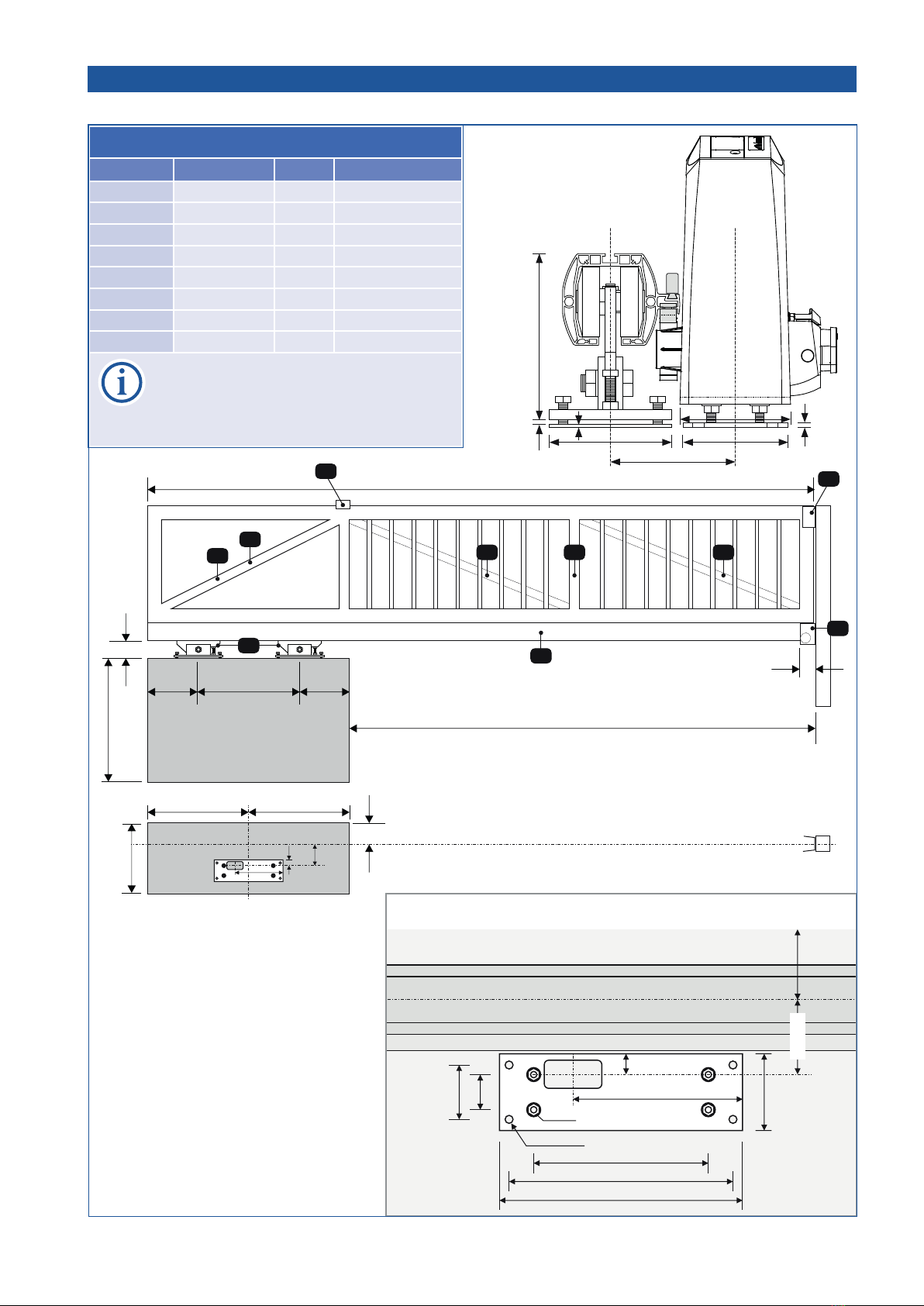
• For perfect function and avoiding damages at the cantilever system, the following planning- and processing
rules have to be strictly followed!
Maintenance
According to the frequency of actuation, but at least once a year, we recommend to carry out the following
maintenance works:
• Check if the rolling gears are standing in-line.
• Check if the gate is smooth running without jamming.
• Check the upper gate guiding.
• Check the assembly screws.
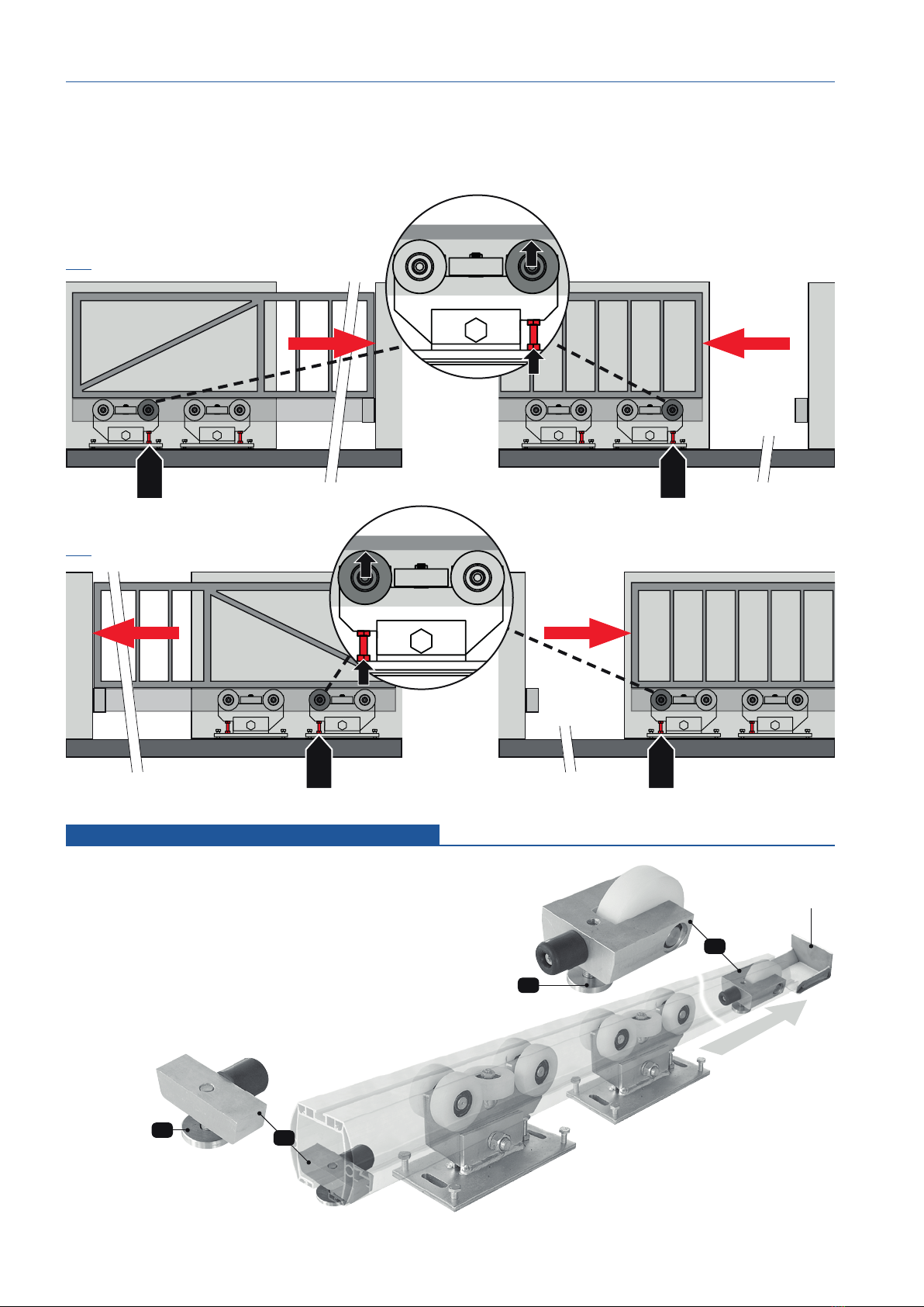
• Check if the door runs correctly into the guide-in bracket resp. guide-in fork bracket.
• Clean the inside of the prole.
This manual is the sole property of the TOUSEK Ges.m.b.H. and may not be made available to competitors. All rights reserved. No part of it may be reproduced without our prior
written permission. We will not accept liability for any claims resulting from misprints or errors. This edition of the manual replaces all earlier publications of the same.
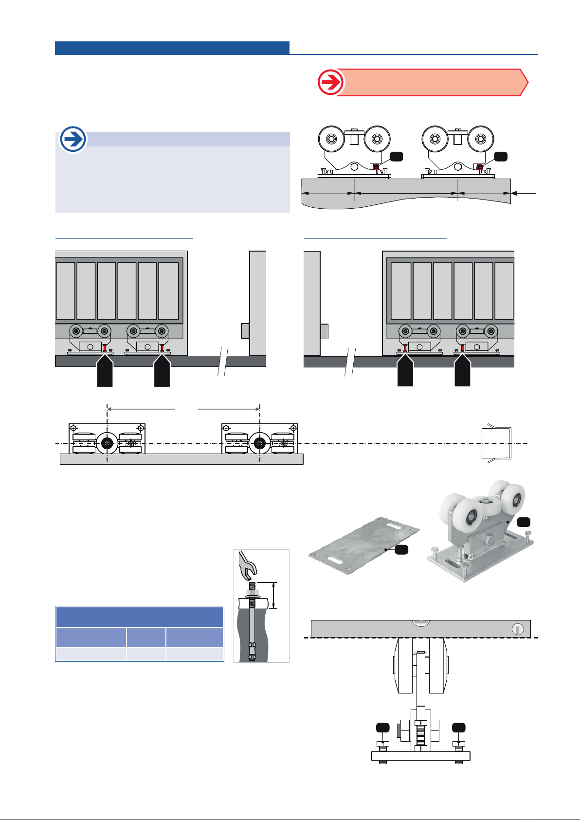
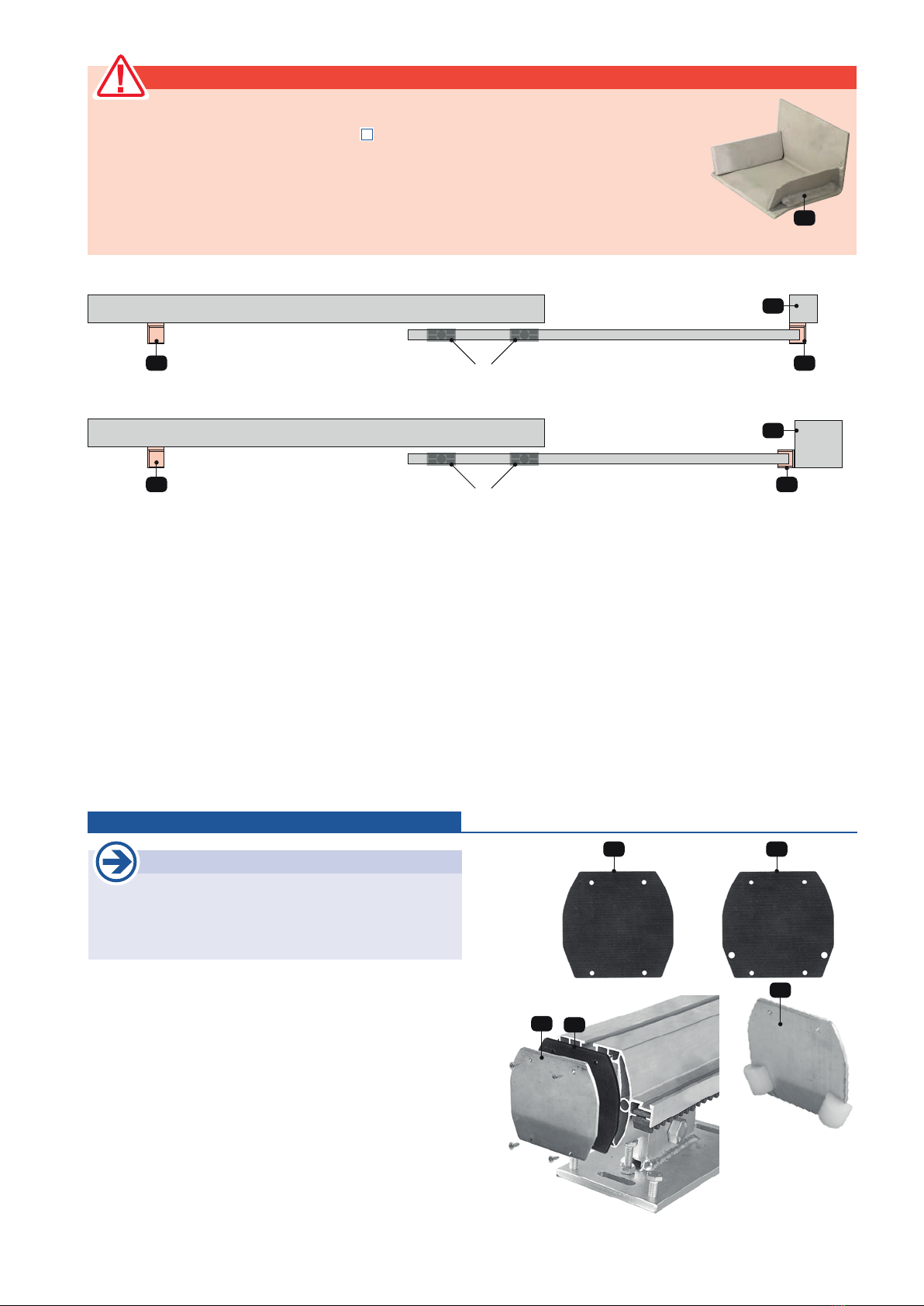
ATTENTION: blocking of the gate (see page 9) !
• Firmly bolted mechanical stops prevent the running of the sliding gate on the rolling gears, when in OPEN or
CLOSED position!
• Examples of xed limit stops as safety devices:
(1) Guide-in bracket, (2) counter pillar