INTRODUCTION MAIN COMPONENTS TOOLS AND
PREPARATION MEASUREMENT LASER BEAM
AXIS ADJUSTMENT
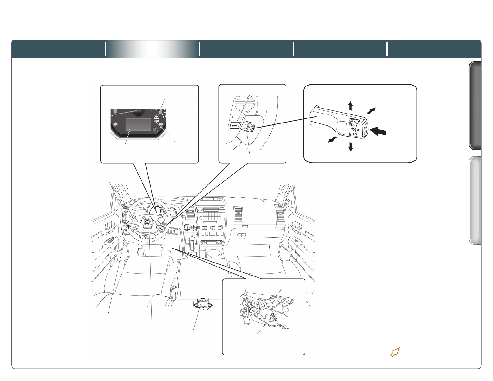
ECM
Laser Radar Sensor
Skid Control ECU Park / Neutral Position Switch
Throttle Body
•Throttle Control Motor
•Throttle Position Sensor
ECU
Laser Emiting Portion
Laser Receiving
Portion
Main Components
NoteNote
INTERIOR COMPONENTS EXTERIOR COMPONENTS
DYNAMIC LASER CRUISE CONTROL SYSTEM 2008 - 2012 SEQUOIA
Quick Training Guide – QT512A
• Thelasersensoremitsalaserbeamtowardthepreceding
vehicle.
• Thelasersensorreceivingportiondetectsthelightreected
fromtheprecedingvehicle.
• The ECU inside the laser sensor then takes the light received
bythesensorandconvertsitintoanelectricalsignal.
• Fromthiselectricalsignal,theprecedingvehicle’sdistance
andanglecanbedetermined.
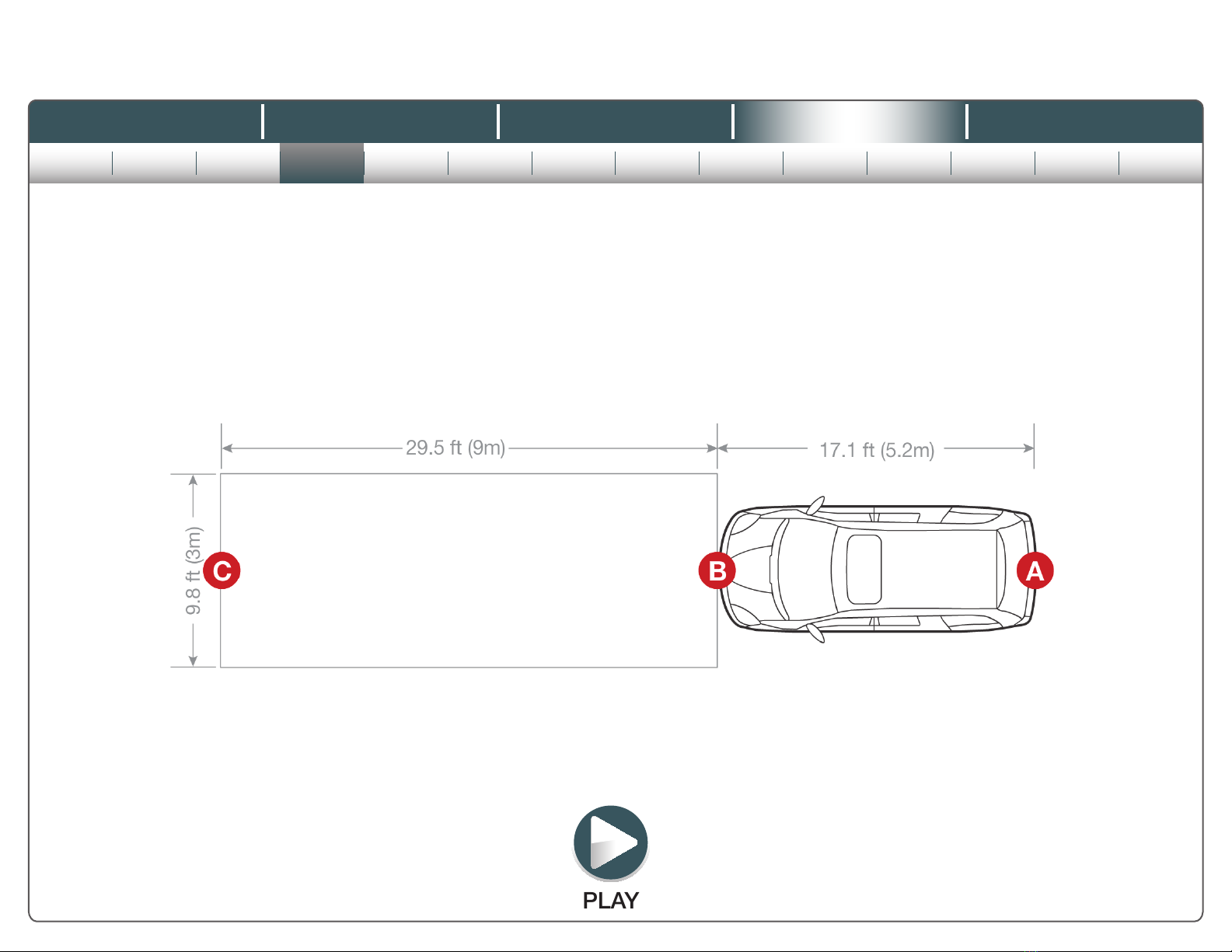
Thefollowinginformationexplainsgeneraloperationofthe
dynamiclasercruisecontrolsensorandcoversthekeypoints
oflasersensoradjustment.
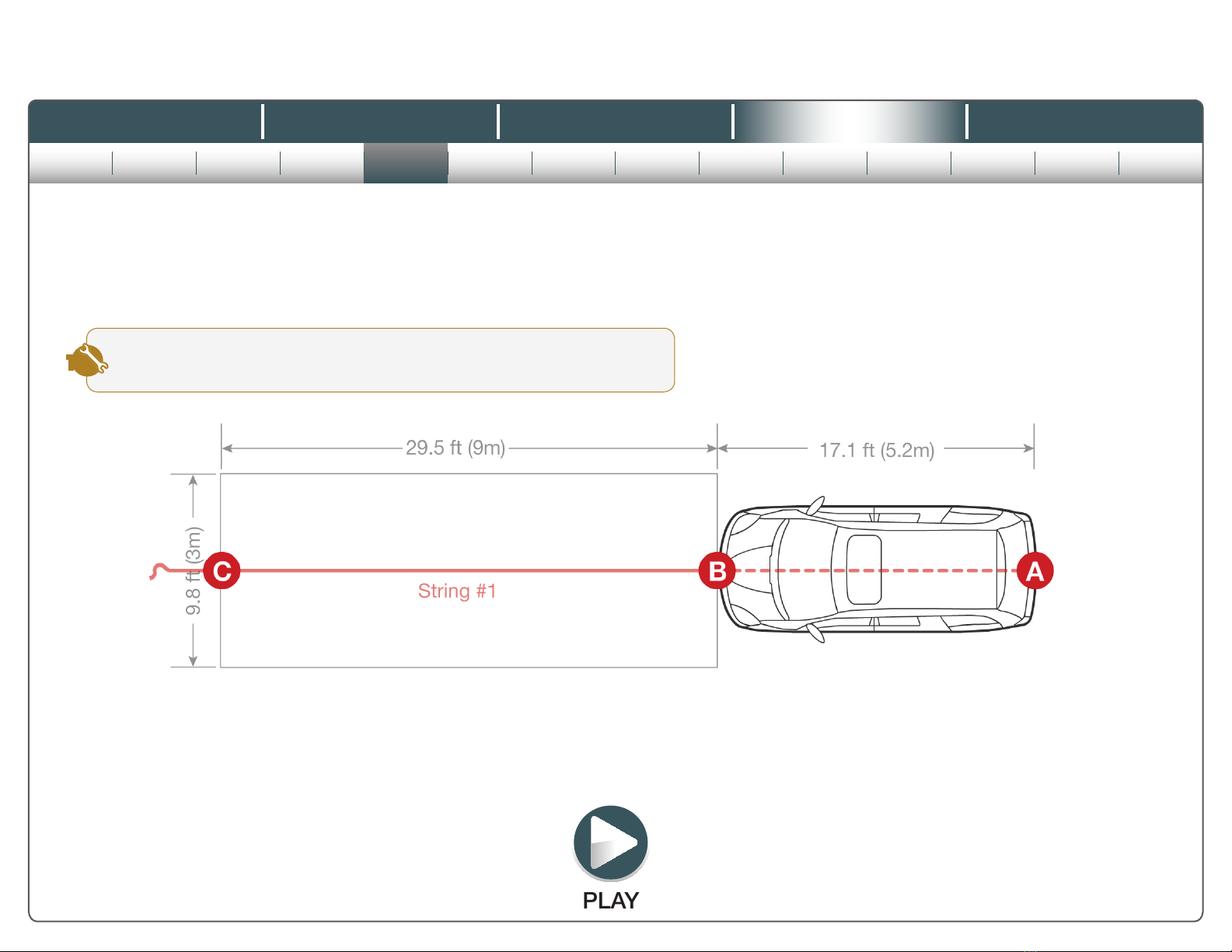
How the laser sensor works:
Alwayskeepthesensorcleantoensurethevehicle-to-
vehicledistancecontroloperatesproperly.Obstructions
suchassnow,iceorplasticobjectscannotbedetectedby
theobstructionsensorandmaycausethedynamiclaser
cruise system to cancel.
©Toyota Motor Sales, U.S.A., Inc., 2012
Click all side tabs