manuals.online logo
Brands
  1. Home
  2. •
  3. Brands
  4. •
  5. TP-Link
  6. •
  7. Control Unit
  8. •
  9. TP-Link TL-SM201 Series User manual

TP-Link TL-SM201 Series User manual

4 5
User's Guide
TL-SM201 Series Module
71030430
Ver:2.0
Made in China
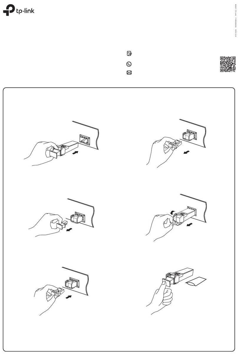
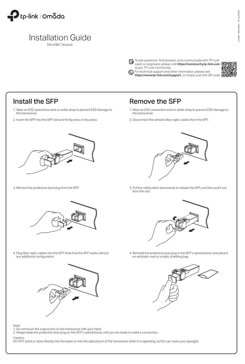
ØTake down the module panel on the Switch
ØPush module into Switch along the track smoothly
ØScrew the module on Switch
ØPlug fiber/UTP into the module, turn on the power supply of the
Switch. Without any configuration manually, the Module can work.
6. Remarks
ØThere are led indicators on the module to show the working
condition. as follows
ØTL-SM201 module support plug and play ,but must turn off power
supply before install/uninstall.
ØTL-SM201 module only install in the TP-LINK Switch, do not install
this card in any other brand Switch.
ØAt present. TL-SM201 module can install in TL-SF2109P, TL-
SF2117P, TL-SF2226P+, TL-SL2226P, TL-SL2226P+ and TL-
SL3226P Switches , we will give a indication in the user's guide
when a new Switch could use this card. See our web site for more
details:
Warning
In order to avoid ESD, do not touch the parts on the circuit including
http://www.tp-link.com.
IC's pins with your hand directly!
7. Working Environment
Power supply: supplied by Switch
Operating Temperature: 0 -40
Storage Temperature: -40 -70
Operating Humidity: 10%-90%(non-condensing)
Storage Humidity: 5%-95%(non-condensing)
Appendix: Contact Information
TP-LINK TECHNOLOGIES CO., LTD.
For help with the installation or operation of the TP-LINK TL-SM201
Series Module, please contact us.
Add: Fl.3, Bldg.R1-B, High-Tech Industrial Park, Shennan Road,
Shenzhen, China
E-mail: [email protected]
Website: http://www.tp-link.com
Link/Act
TX RX
FIBER MODULE UTP MODULE
Link/Act
FDX/Col
100M
1 2 3
COPYRIGHT & TRADEMARKS
Specifications are subject to change without notice. is a
registered trademark of TP-LINK Technologies Co., Ltd. Other
brands and product names are trademarks or registered trademarks
of their respective holders.
No part of the specifications may be reproduced in any form or by
any means or used to make any derivative such as translation,
transformation, or adaptation without permission from TP-LINK
Technologies Co., Ltd. Copyright ©2005 TP-LINK Technologies Co.,
Ltd. All rights reserved.
1. Introduction
TL-SM201 series modules use fiber or Cat.5 Twisted-pair as
transmission media, cooperate with TP-LINK Switches. It can
effectively extend the diameter and bandwidth of the workgroup. TL-
SM201 series of fiber module is fully compliant with IEEE802.3u
protocol. It's wavelengh is about 1310nm. TL-SM201U UTP module is
fully compliant with IEEE802.3u protocol, support 10/100M Auto-
Negotiation and Auto-MDI/MDIX function. TL-SM201 series of module
is easy to use, can be installed inside the Switch which supply power
directly. TL-SM201 module can cooperate with some sort of TP-LINK
Switches to work .The led indicators upon the module indicate working
condition of the TL-SM201 Series Modules.
2. Naming
TL-SM201U: 100Base-TX Cat.5 Twisted-pair ports (UTP) module,RJ-
45 connector
TL-SM201CM:100BaseFX Multi-mode fiber module,SC connector
TL-SM201CS: 100Base-FX Single-Mode fiber module,SC connector
TL-SM201TM: 100Base-FX Multi-mode fiber module, ST connector
3. Type of module and the distance of transmission
THE TYPEOF MODULE MAXIMAL DISTANCE
TL-SM201U X 100m
TL-SM201CM X 2000m
TL-SM201CS-20 X 20000m
TL-SM201CS-40 X 40000m
TL-SM201CS-60 X 60000m
TL-SM201TM X 2000m
4. Features of the product
ØMulti-mode and Single-Mode fiber module operate at 1310nm
ØMulti-mode fiber module use the 50/125um, 62.5/125um fiber;
Single-Mode fiber module use the 9/125um fiber . UTP module
use the ordinary Cat.5 Twisted-pair
ØComply with IEEE802.3u protocol and support full duplex mode
ØTL-SM201U UTP module support the 10/100M Auto-Negotiation
andAuto-MDI/MDIXfunction
ØThe maximal transmission distance of Multi-mode/Single-Mode/
Cat.5 Twisted-pair is 2000m/60000m/100m
ØOption for some type TP-LINK Switches
ØLED indicators of the module indicate the module status
ØPlug and play
5. InstallationGuide
ØTurn off the power supply
TP-LINK SWITCH
DISTANCE:X
TL-SM201 FIBER/CABLE
Remote device
DTE
Other TP-Link Control Unit manuals

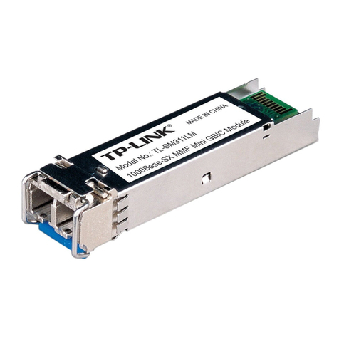
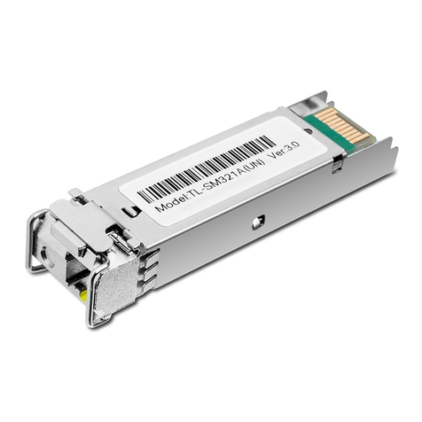
TP-Link TL-SM321A User manual

TP-Link

TP-Link TL-SM321A User manual

TP-Link TL-SM311 Series User manual

TP-Link

TP-Link TL-SM311 Series User manual

TP-Link kasa smart KE100 User manual

TP-Link

TP-Link kasa smart KE100 User manual

TP-Link kasa smart KE100 User manual

TP-Link

TP-Link kasa smart KE100 User manual

TP-Link TL-SM311LS User manual

TP-Link

TP-Link TL-SM311LS User manual

TP-Link Omada SM311LS V5 User manual

TP-Link

TP-Link Omada SM311LS V5 User manual

TP-Link ecoNET300 Specification sheet

TP-Link

TP-Link ecoNET300 Specification sheet

TP-Link Kasa Smart KE100 KIT User manual

TP-Link

TP-Link Kasa Smart KE100 KIT User manual

TP-Link TL-SM321A User manual

TP-Link

TP-Link TL-SM321A User manual

TP-Link TL-SM311LS User manual

TP-Link

TP-Link TL-SM311LS User manual

TP-Link DS-PMA-C+ V1 User manual

TP-Link

TP-Link DS-PMA-C+ V1 User manual

TP-Link kasa smart KE100 V1.20 User manual

TP-Link

TP-Link kasa smart KE100 V1.20 User manual

TP-Link TL-SM331T User manual

TP-Link

TP-Link TL-SM331T User manual

TP-Link TL-SM321A User manual

TP-Link

TP-Link TL-SM321A User manual

TP-Link KLM100 User manual

TP-Link

TP-Link KLM100 User manual

TP-Link TL-SM321A User manual

TP-Link

TP-Link TL-SM321A User manual

TP-Link kasa smart KE100 User manual

TP-Link

TP-Link kasa smart KE100 User manual

TP-Link TL-SM331T User manual

TP-Link

TP-Link TL-SM331T User manual

Popular Control Unit manuals by other brands

Sierra Wireless AirPrime AR7584 Hardware integration guide

Sierra Wireless

Sierra Wireless AirPrime AR7584 Hardware integration guide

Lincoln A Series manual

Lincoln

Lincoln A Series manual

AVL DITEST MCS 120 user manual

AVL DITEST

AVL DITEST MCS 120 user manual

W&H Osstell ISQ Instructions for use

W&H

W&H Osstell ISQ Instructions for use

ADDAC System ADDAC308 LIGHT TO CV Assembly guide

ADDAC System

ADDAC System ADDAC308 LIGHT TO CV Assembly guide

Pentair FLECK 5810 XTR2 Service manual

Pentair

Pentair FLECK 5810 XTR2 Service manual

Gecko In.Touch 0608-521012 Tech book

Gecko

Gecko In.Touch 0608-521012 Tech book

Allen-Bradley 140G-H Installation

Allen-Bradley

Allen-Bradley 140G-H Installation

Jaga DBEC.11 installation instructions

Jaga

Jaga DBEC.11 installation instructions

Alcolizer HH3 Work Instruction

Alcolizer

Alcolizer HH3 Work Instruction

Locinox Turnitec user guide

Locinox

Locinox Turnitec user guide

NEC NE3108-005 user guide

NEC

NEC NE3108-005 user guide

Gemu 8357 Installation, operating and maintenance instructions

Gemu

Gemu 8357 Installation, operating and maintenance instructions

Interscan Corporation ACCUSAFE F901 instruction manual

Interscan Corporation

Interscan Corporation ACCUSAFE F901 instruction manual

National Instruments FieldPoint FP-1001 user manual

National Instruments

National Instruments FieldPoint FP-1001 user manual

M-system R7D-EA16 instruction manual

M-system

M-system R7D-EA16 instruction manual

Danfoss ESMD installation guide

Danfoss

Danfoss ESMD installation guide

Keyscan CIM-LINK Setup guide

Keyscan

Keyscan CIM-LINK Setup guide

manuals.online logo
manuals.online logoBrands
  • About & Mission
  • Contact us
  • Privacy Policy
  • Terms and Conditions

Copyright 2025 Manuals.Online. All Rights Reserved.