Celsius, slide the °C/°F button to the desired position.
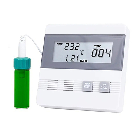
DISPLAYING PROBE 1 OR PROBE 2
Slide the PROBE switch to the desired position (1 or 2) to
display the desired temperature sensor readings.
MINIMUM AND MAXIMUM MEMORY
There are four points that are automatically recorded into
memory:
• Minimum (MIN) Probe 1 (P1) Temperature
Achieved with time-of-day and date achieved
• Maximum (MAX) Probe 1 (P1) Temperature
Achieved with time-of-day and date achieved
• Minimum (MIN) Probe 2 (P2) Temperature
Achieved with time-of-day and date achieved
• Maximum (MAX) Probe 2 (P2) Temperature
Achieved with time-of-day and date achieved
Minimum and maximum temperature memories
are NOT programmable. The minimum temperature
recorded into memory is the minimum temperature
achieved since the last time the memory was cleared.
The maximum temperature recorded into memory is
the maximum temperature achieved since the last time
the memory was cleared. The minimum and maximum
temperature memories are maintained over the period
since the memory was cleared.
Minimum and maximum memories are recorded for both
sensors regardless of the display mode.
VIEWING MIN/MAX MEMORY
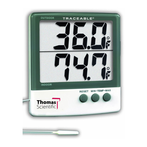
1. Slide the PROBE switch to the desired position (1 or
2) to display the desired temperature sensor readings.
2. Slide the DISPLAY switch to the MIN MAX position.
The display will show the current temperature and
minimum/maximum memory for the selected probe.
VIEWING MIN/MAX MEMORY DATE/TIME
1. Slide the PROBE switch to the desired position (1 or
2) to display the desired temperature sensor readings.
2. Slide the DISPLAY switch to the MIN MAX position.
The display will show the current temperature and
minimum/maximum memory for the selected probe.
3. Press the EVENT DATE TIME button, the minimum
temperature achieved by that probe along with the
time-of-day/date the temperature was achieved will
appear on the display (indicated by MIN and TIME
appearing on the display).
4. Press the EVENT DATE TIME button a second time,
the maximum temperature achieved by that probe
along with the time-of-day/date the temperature was
achieved will appear on the display (indicated by
MAX and TIME appearing on the display).
Note: If no button is pressed for fteen (15) seconds,
the unit automatically returns to the current temperature
display mode.
5. To exit from the memory display mode, press and
release the EVENT DATE TIME button until MIN or
MAX no longer appears on the display, or simply do
not press any button for fteen (15) seconds.
CLEARING THE MINIMUM/MAXIMUM MEMORY
1. Slide the PROBE switch to the desired position (1 or
2) to display the desired temperature sensor readings.
2. Slide the DISPLAY switch to the MIN MAX position.
The display will show the current temperature and
minimum/maximum memory for the selected probe.
3. Press the CLEAR MIN MAX button to clear the
minimum and maximum memories for the probe
being displayed.
ALARMS
Both temperature sensor (P1/P2) alarm limits may be set
in 0.1° increments. Probe 1 and Probe 2 alarm limits are
set independent of each other.
With the alarm switch set to the ON position:
-The unit will sound an alarm and ash the corresponding
LED (P1/P2) when the temperature measured is outside
the alarm limits that have been set (equal to or lower than
the low alarm set point, or equal to or greater than the
high alarm set point).
-The alarm will sound regardless of which sensor is being
displayed and regardless of the display mode. Example:
If Probe 1 is being displayed and the DISPLAY switch is
set to MIN MAX, but Probe 2 reaches an alarm condition,
the alarm will sound and the P2 LED will ash.
SETTING THE TEMPERATURE ALARM LIMITS
1. Slide the PROBE switch to the desired position (1 or
2) to display the desired temperature sensor readings.
2. Slide the DISPLAY switch to the ALARM position.
The display will show the current temperature and
low/high alarm set points for the selected probe.
3. While in the alarm display mode, pressing the SELECT
button will allow the alarm limits to be set.
Pressing the SELECT button will cause the digits to
ash in the following order: Low Alarm 1st Digits→Low
Alarm 2nd Digit→Low Alarm Decimal Digit→ High Alarm
1st Digits→High Alarm 2nd Digit→High Alarm Decimal
Digit→No digits ashing (value set).
4. Once the desired item is ashing, pressing the
ADVANCE button will increment the value.
5. With the desired alarm set points appearing on the
display, press the SELECT button until no digits
are ashing on the display. The alarm settings will
be saved.
Note: While in the setting mode, if no button is pressed
for fteen (15) seconds, the unit automatically exits from
the setting mode.
VIEWING THE TEMPERATURE ALARM LIMITS
1. Slide the PROBE switch to the desired position (1 or
2) to display the desired temperature sensor readings.
2. Slide the DISPLAY switch to the ALARM position.
The display will show the current temperature and
low/high alarm set points for the selected probe.
SPECIFICATIONS
Range: -58.00 to 158.00 °F
-50.00 to 70.00 °C
Accuracy: ±0.05 °C when within ±2 °C of the
tested standard point(s); ±1°C
otherwise.**
Resolution: 0.01°
Update Rate: 1 second (FAST)
10 seconds (NORMAL)
Battery: 2 each AAA (1.5V)
Probe Supplied: One (1) stainless steel, triple purpose
probe for use in the P1 socket.
Tested Points:
Model 4241-- Test point of 0.00°C.
Model 4242-- Test point of 25.00°C.
Model 4243-- Test point of 37.00°C.
Model 4244-- Test points of 0.00°C, 25.00°C and 37.00°C.
**Thermometer is tested/certied with the supplied probe
plugged in to the P1 socket. The specied accuracy is
valid only when using the supplied probe in the P1 socket.
SETTING THE TIME-OF-DAY/DATE
Slide the DISPLAY switch to the DATE TIME position, the
display will show the time-of-day and date.
While in the time-of-day/date display, pressing
the SELECT button will allow the date and time
to be set. Pressing the SELECT button will
cause the digits to ash in the following order
Year→Month→Day→Hours→Minutes →12/24 hour
time→No digits ashing (value set). Once the desired
item is ashing, pressing the ADVANCE button will
increment the value.
With the desired time-of-day/date appearing on the
display, press the SELECT button until no digits are
ashing on the display. The time-of-day/date will be
saved.
Note: While in the setting mode, if no button is pressed
for fteen (15) seconds, the unit automatically exits from
the setting mode.
VIEWING THE TIME-OF-DAY/DATE
To view the time-of-day/date, slide the DISPLAY switch to
the DATE TIME position.
DISPLAYING °F OR °C
To display the temperature readings in Fahrenheit or
ENABLE/DISABLE ALARMS
To enable the alarm to activate when a temperature
measured is outside the alarm limits, slide the ALARM
switch to the ON position.
When the alarm is enabled, both Probe 1 and Probe 2
alarm set points will be monitored. If either sensor reaches
an alarm condition, the alarm will activate. It is not possible
to enable the alarm for one sensor and disable the alarm
for the other sensor.
To disable the alarm so that no alarm sounds when a
temperature measured is outside the alarm limits, slide
the ALARM switch to the OFF position.
ALARM SOUNDING
With the alarm enabled, the unit will sound an alarm and
the corresponding (P1/P2) red LED will ash when a
temperature being measured is outside the alarm limits
that have been set (equal to or lower than the low alarm
set point, or equal to or greater than the high alarm set
point). Until it has been acknowledged/silenced (see
the “Acknowledge/Silence An Alarm” section), the alarm
will sound and corresponding (P1/P2) red LED will ash
continuously for the rst sixty (60) seconds. After 60
seconds, the alarm will sound and LED will ash for ten
(10) seconds every minute.
If the alarm is sounding based on the low alarm limit and
the probe temperature is being displayed, “LO ALM” will
also ash on the display. If the alarm is sounding based
on the high alarm limit and the probe temperature is
being displayed, “HI ALM” will ash on the display.
The alarm will sound and corresponding LED will ash
regardless of which sensor is being displayed and
regardless of the display mode. Example: If Probe 1 is
being displayed and the DISPLAY switch is set to MIN
MAX, but Probe 2 reaches an alarm condition, the alarm
will sound and the P2 LED will ash.
The unit will continue to alarm and ash the corresponding
(P1/P2) red LED until the alarm has been acknowledged/
silenced by either pressing the SILENCE ALM button or
by sliding the ALARM switch to the OFF position (see the
“Acknowledge/Silence An Alarm” section). The unit will
continue to alarm and ash the corresponding (P1/P2) red
LED even if the temperature being measured returns to an
in-range/non-alarm condition.
ACKNOWLEDGE/SILENCE AN ALARM
While alarming, the alarm may be acknowledged/silenced
in one of the following ways:
1. Slide the ALARM switch to the OFF position.
Setting the ALARM switch to the OFF position will
silence the alarm, but when it is switched back to the
ON position, if the temperature being measured is
still in an alarm condition, the alarm will sound.
Setting the ALARM switch to the OFF position
prevents any/all alarms from sounding.


