manuals.online logo
Brands
  1. Home
  2. •
  3. Brands
  4. •
  5. Traceable
  6. •
  7. Thermometer
  8. •
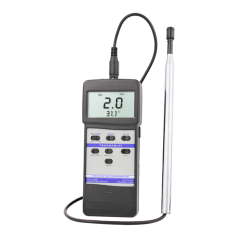
  9. Traceable 4189 User manual

Traceable 4189 User manual

Traceable
®
is a registered trademark of Control Company ©2009 Control Company. 92-4189-00 Re . 1 040909
SPECIFICATIONS
Temperature—
Range: 32.00 to 122.00 °F / 0.00 to 50.00 °C
Resolution: 0.01°
Humidity—
Range: 0.00 to 95.00% RH
Resolution: 0.01%
ew Point—
Range: -13.50 to 120.10 °F / 25.30 to 48.90 °C
Resolution: 0.01°
ata output: Computer interface
ata Logging: 1000 reading capability
OPERATION
1. Attach the humidity/temperature probe to the meter. (The cable and connectors are keyed,
do not insert the cable incorrectly and force it.)
2. Turn the meter on by pressing the POWER button.
3. Take the desired measurements.
4. Turn the meter off by pressing and holding the POWER button, release the POWER button
when the meter emits a continuous beep. To preser e battery life, always turn the meter off when
not in use.
SELECTING °F OR °C (Temperature/ ew Point)
1. Turn the meter on by pressing the POWER button.
2. Press and hold the SET/LOGGER button until “code” appears at the bottom of the
display.
3. Release the SET/LOGGER button “1000” will appear at the top of the display.
4. Press the REC/ENTER button. “
0
F” will appear at the bottom of the display and “0” or “1”
will appear at the top of the display.
5. Press the FUNCTION/SEND button to select the desired unit of measure (0 = °C 1 = °F).
Note: When pressing the FUNCTION/SEND button, “
0
F” will not change at the bottom of
the display.
6. With the desired alue on the display, press the REC/ENTER button to confirm and sa e
the selection.
7. Press the HOLD/ESC button to return to the measurement display.
The unit of measure selected will be the default unit of measure for both temperature and dew
point until it is re-set.
SELECTING HUMI ITY OR EW POINT ISPLAY
1. Turn the meter on by pressing the POWER button.
2. Each press of the FUNCTION/SEND button will toggle the top display between showing
Humidity (“%RH” appears) and Dew Point Temperature (“Dew” appears). Temperature will
always appear at the bottom of the display.
The Dew Point temperature will be displayed in the same unit of measure as the temperature
display (See the “Selecting °F or °C” section).
HOL FUNCTION
The hold function allows the readings on the display to be “frozen” so that they may be recorded.
1. Press the HOLD/ESC button to “freeze” the display at the current reading. “HOLD” will appear
at the top of the display.
While in the hold mode, pressing the REC/ENTER, FUNCTION/SEND, or SET/LOGGER b ttons
will have no affect and will not change the “frozen” reading.
2. Once the reading has been recorded, press the HOLD/ESC button to return the display to the
current reading. “HOLD” will no longer appear on the display.
RECOR MO E (Min/Max Memories)
While in the Record Mode, the maximum and minimum readings for Humidity or Dew Point
(depending on the display mode) will be recorded. Also, while in the Record Mode, the Automatic
Shutoff feature is disabled so that long term monitoring may be performed.
To enter the Record Mode, press the REC/ENTER button. “REC.” will appear on display.
To recall the maximum and minimum readings since entering the Record Mode (“REC” appearing
on the display), press the REC/ENTER button.
The first press of the REC/ENTER button will display the maximum reading achie ed since
entering the Record Mode. (“MAX” will appear on the display).
The second press of the REC/ENTER button displays the minimum reading achie ed since
entering the Record Mode. (“MIN” appear on the display).
To return the display to the current reading, press the HOLD/ESC button. “MAX” or “MIN” will no
longer appear on the display.
To exit from the Record Mode, press and hold the REC/ENTER button for 3 seconds. “REC” will
no longer appear on the display. The maxim m and minim m readings are a tomatically cleared
once the Record Mode has been exited.
AUTOMATIC SHUTOFF (Enable/ isable)
With the Automatic Shutoff feature enabled, after 10 minutes, if no button has been pressed, the
meter will automatically shut off to preser e battery life.
When automatic shutoff is enabled, prior to shutting off, the meter will alarm to indicate that it is
about to turn off. To pre ent the meter from shutting off at this point, press any button twice
(except POWER).
The automatic shutoff feature setting is o erridden while in the Record Mode. (See the “Record
Mode” section)
To Enable/Disable the Automatic Shutoff feature:
1. Turn the meter on by pressing the POWER button.
2. Press and hold the SET/LOGGER button until “code” appears on the display.
3. Release the SET/LOGGER button “1000” will appear on the top display.
4. Press the REC/ENTER button,
0
F will appear at the bottom of the display.
5. Press the SET/LOGGER button until “OFF” appears at the bottom of the display.
6. Press the FUNCTION/SEND button to enable/disable the automatic shutoff feature.
7. (0 = Disabled 1 = Enabled).
Note: When pressing the FUNCTION/SEND button, “OFF” will not change at the bottom of
the display.
8. With the desired alue on the display, press the REC/ENTER button to confirm and sa e the
selection.
9. Press the HOLD/ESC button to return to the measurement display.
The automatic shutoff feature will now be enabled/disabled until it is re-set.
ATA LOGGER
The built in data logger function can store up to 1000 Humidity/Temperature or Dew
Point/Temperature alues. The alues that are recorded are dependant upon the display mode
that has been selected. (See the “Selecting Humidity or Dew Point Display” section.) If Humidity
and Temperature are being displayed, then Humidity and Temperature will be logged. If Dew
Point and Temperature are being displayed, then Dew Point and Temperature will be logged.
NOTE: There is no annunciator to differentiate the Dew Point temperature reading from the
Temperature reading in the data that is output/logged (See the “Real-Time Data Output” section.),
it is best to ha e the meter displaying Relati e Humidity and Temperature when using the data
logger function.
The sampling rate for the data logger may be set in the following increments 0, 1, 2, 10, 30, 60,
600, 1800, and 3600 seconds. (See the “Adjusting Data Logger Sampling Rate” section.)
Adjusting ata Logger Sampling Rate
The sampling rate for the data logger may be set in the following increments 0, 1, 2, 10, 30, 60,
600, 1800, and 3600 seconds.
1. Turn the meter on by pressing the POWER button.
2. Press and hold the SET/LOGGER button until “code” appears at the bottom of the display.
3. Release the SET/LOGGER button. “1000” will appear at the top of the display.
4. Press the REC/ENTER button. “
0
F” will appear at the bottom of the display.
5. Press the SET/LOGGER button. “SEC” will appear at the bottom of the display. The number
that appears at the top of the display is the data logger sampling rate (seconds).
6. Press the FUNCTION/SEND button to select the desired sampling rate from the a ailable
options.
7. With the desired alue on the display, press the REC/ENTER button to confirm and sa e the
selection.
8. Press the HOLD/ESC button to return to the measurement display.
The data logger sampling rate selected will be the default alue until it is re-set.
Automatic ata Logging
Set the desired data logger sampling rate. (See the “Adjusting Data Logger Sampling Rate”
section.) For automatic data logging, the sampling rate must not be set to zero.
If desired, clear the data in the data logger memory. (See the “Clearing the Data Logger Memory”
section.)
Enter the Record Mode by pressing the REC/ENTER button. “REC.” will appear on display.
To begin automatic data logging, press the SET/LOGGER button. “A” will appear at the top of the
display and the sampling rate will flash once on the display.
NOTE:
1. If “A” does not remain at the top of the display, the sampling rate is set to zero, see the
“Adjusting Data Logger Sampling Rate” section to set the sampling rate.
2. If the display flashes continuously when the SET/LOGGER button is pressed, this indicates that
the data logger memory is full. See the “Exporting the Data Logger Memory” to export the readings
that ha e been recorded, and/or the “Clearing the Data Logger Memory” section to clear the
memory so that more data may be recorded.
“A” will remain on the display and will flash each time a reading is recorded. “REC” and “A”
appearing on the display indicate that the meter is in the automatic data logger mode.
Once the data logger memory is full, the display will flash continuously. See the “Exporting the
Data Logger Memory” section to export the readings that ha e been recorded, and/or the “Clearing
the Data Logger Memory” section to clear the memory so that more data may be recorded.
To stop data logging, press the SET/LOGGER button. “A” will no longer appear at the top of the
display.
Automatic data logging may be resumed by pressing the SET/LOGGER button. “A” will appear at
the top of the display.
To exit from the Record Mode, press and hold the REC/ENTER button for 3 seconds. “REC” will no
longer appear on the display.
TRACEABLE
®
HYGROMETER/THERMOMETER/DEW POINT METER
WITH DATA LOGGER &
C
OMPUT
ER
OUTPUT
INSTRUCTIONS
Traceable
®
is a registered trademark of Control Company ©2009 Control Company. 92-4189-00 Re . 1 040909
The data logged will remain the data logger memory until it is cleared. (See the “Clearing the Data
Logger Memory” section.)
MANUAL ATA LOGGING
Set the data logger sampling rate to zero “0”. (See the “Adjusting Data Logger Sampling Rate”
section.) If desired, clear the data in the data log memory. (See the “Clearing the Data Logger
Memory” section.) Enter the Record Mode by pressing the REC/ENTER button. “REC.” will appear
on display. Each time the SET/LOGGER button is pressed, the reading will be recorded in the data
logger memory. “A” will appear at the top of the display each time a reading is recorded into
memory.
NOTE:
1. If “A” remains at the top of the display, the sampling rate is not set to zero, see the “Adjusting
Data Logger Sampling Rate” section to set the sampling rate to zero.
2. If the display flashes when the SET/LOGGER button is pressed, this indicates that the data
logger memory is full. See the “Exporting the Data Logger Memory” to export the readings that
ha e been recorded, and/or the “Clearing the Data Logger Memory” section to clear the memory so
that more data may be recorded.
Once the data logger memory is full, the display will flash continuously. See the “Exporting the
Data Logger Memory” to export the readings that ha e been recorded, and/or the “Clearing the
Data Logger Memory” section to clear the memory so that more data may be recorded.
To exit from the Record Mode, press and hold the REC/ENTER button for 3 seconds. (“REC” will
no longer appear on the display).
The data logged will remain the data log memory until it is cleared. (See the “Clearing the Data Log
Memory” section.)
isplaying the Remaining ata Logger Memory
The data logger will store and retain the readings until they ha e been cleared. Once the
maximum number of readings (1000) ha e been recorded in the data logger, it must be cleared in
order to record more data. The balance of the remaining data logger memory may be iewed by
following this procedure.
1. Turn the meter on by pressing the POWER button.
2. Press and hold the SET/LOGGER button until “code” appears at the bottom of the
display.
3. Release the SET/LOGGER button. “1000” will appear at the top of the display.
4. Press the REC/ENTER button. “
0
F” will appear at the bottom of the display.
5. Press the SET/LOGGER button until “CnT” appears at the bottom of the display.
6. With “CnT” at the bottom of the display, the number that appears at the top of the display
is the remaining data logger memory.
7. When finished iewing, press the HOLD/ESC button to return to the measurement display.
Exporting the ata Logger Memory
The data logger will store and retain the readings until they ha e been cleared. To export the data
logger memory, accessory item# 4136 is required (See the “Optional Accessories” section).
1. Attach one end of the computer cable to the “RS-232 OUT” port on the meter and the other
end to the PC.
2. Make certain that “HOLD” and/or “REC” do not appear on the display. -If “HOLD” appears
on the display, press the HOLD/ESC button. (“HOLD” will no longer appear on the display.)
-If “REC” appears on the display, press and hold the REC/ENTER button for 3 seconds.
(“REC” will no longer appear on the display.)
3. Press and hold the FUNCTION/SEND button until “232” appears at the bottom of the
display. The meter is now ready to export the data logger memory.
4. Prepare the PC software to recei e the data.
5. Once the PC software is ready to recei e the data, press the FUNCTION/SEND button.
The display will flash slowly while the data is being exported. The display will flash rapidly once all
of the data has been exported.
6. Once the data has been exported, press the HOLD/ESC button to return to the
measurement display.
Clearing the ata Logger Memory
The data logger will store and retain the readings until they ha e been cleared. Once the
maximum number of readings (1000) ha e been recorded in the data logger, it must be cleared in
order to record more data.
1. Turn the meter on by pressing the POWER button.
2. Press and hold the SET/LOGGER button until “code” appears at the bottom of the
display.
3. Release the SET/LOGGER button. “1000” will appear at the top of the display.
4. Press the REC/ENTER button. “
0
F” will appear at the bottom of the display.
5. Press the SET/LOGGER button until “Clr” appears at the bottom of the display.
6. With “Clr” appearing at the bottom of the display, the number that appears at the top of
the display is the used data logger memory.
7. Press the FUNCTION/SEND button. “0” will appear at the top of the display indicating the
memory will be cleared.
8. Press the REC/ENTER button to confirm and sa e the selection.
9. Press the HOLD/ESC button to return to the measurement display.
REAL-TIME ATA OUTPUT
The meter features a computer output ia 3-pole 3.5 mm plug that will output the current display
readings in real-time. The output is a 16-digit data stream that may be utilized by accessory item#
4136 (See the “Optional Accessories” section) or by user specific applications.
A lead with a 3-pole 3.5 mm jack on one end (plugs into “RS 232 OUT”) and a 9-pin female D-
Subminiature connector on the other end (plugs into the PC’s serial port) will be required to link the
instrument with a PC.
ALL OPERATION IFFICULTIES
If this meter does not function properly for any reason, replace the battery with a new, high-
quality battery (see the “Battery Replacement” section). Low battery power can occasionally
cause an number of “apparent” operational difficulties. Replacing the battery with a new fresh
battery will sol e most difficulties.
BATTERY REPLACEMENT
An erratic display, faint display, no display, or a battery icon appearing on the display are all
indicators that the battery needs replacement. Remo e the battery co er. Remo e the exhausted
battery and replace it with a new 9 olt alkaline battery. Replace the battery co er.
OPTIONAL ACCESSORIES
Cat. No. 4136 ata Acquisition System Accessory Powerful and easy to use computer data
capture/data logging program works with Traceable® Instruments with computer output. Records
inter al readings from 1 to 10,000 seconds; displays minimum/maximum readings; and utilizes an
alarm mode that permits the user to be notified isually, audibly, and by email when an alarm is
triggered. Data is stored to a file that can be printed in any report or spreadsheet format.
Networking ser er/client capability allows the captured data to be monitored on a remote
workstation and/or by email. It is designed to work with Windows® 98/Me/NT/2000/XP/Vista.
Includes a CD, a 6-foot cable (supplied USB and serial connections) that plugs into the instrument
and computer. Accessory extension cables expand cable length to 300 feet.
WARRANTY, SERVICE, OR RECALIBRATION
For warranty, ser ice, or recalibration, contact:
CONTROL COMPANY
4455 Rex Road
Friendswood, Texas 77546 USA
Ph. 281-482-1714 Fax 281-482-9448
E- ail sales@control3.co
www.control3.co
Control Co pany is ISO 9001 Quality-
Certified by DNV and ISO 17025 accredited
as a Calibration Laboratory by A2LA.

Other Traceable Thermometer manuals

Traceable 4202 Series User manual

Traceable

Traceable 4202 Series User manual

Traceable 4330 User manual

Traceable

Traceable 4330 User manual

Traceable ULTRA User manual

Traceable

Traceable ULTRA User manual

Traceable PLATINUM User manual

Traceable

Traceable PLATINUM User manual

Traceable 5651TR User manual

Traceable

Traceable 5651TR User manual

Traceable 4000 User manual

Traceable

Traceable 4000 User manual

Traceable 4351 User manual

Traceable

Traceable 4351 User manual

Traceable 4482 User manual

Traceable

Traceable 4482 User manual

Traceable WORKHORSE 4425 User manual

Traceable

Traceable WORKHORSE 4425 User manual

Traceable 4126 User manual

Traceable

Traceable 4126 User manual

Traceable 4344 User manual

Traceable

Traceable 4344 User manual

Traceable RTD PLATINUM User manual

Traceable

Traceable RTD PLATINUM User manual

Traceable 4202 Series User manual

Traceable

Traceable 4202 Series User manual

Traceable 90002-03 User manual

Traceable

Traceable 90002-03 User manual

Traceable 4482 User manual

Traceable

Traceable 4482 User manual

Traceable 4134 User manual

Traceable

Traceable 4134 User manual

Traceable 4800 User manual

Traceable

Traceable 4800 User manual

Traceable LOLLIPOP 4371 User manual

Traceable

Traceable LOLLIPOP 4371 User manual

Traceable 4351 User manual

Traceable

Traceable 4351 User manual

Traceable 90000-39 User manual

Traceable

Traceable 90000-39 User manual

Traceable 90002-03 User manual

Traceable

Traceable 90002-03 User manual

Traceable 9446075 User manual

Traceable

Traceable 9446075 User manual

Traceable 4487 User manual

Traceable

Traceable 4487 User manual

Traceable 98767-45 User manual

Traceable

Traceable 98767-45 User manual

Popular Thermometer manuals by other brands

Braun ThermoScan IRT 6515 owner's manual

Braun

Braun ThermoScan IRT 6515 owner's manual

PCsensor TEMPer2 user manual

PCsensor

PCsensor TEMPer2 user manual

Microlife VT 1831 quick start guide

Microlife

Microlife VT 1831 quick start guide

P3 International P0250 Specifications

P3 International

P3 International P0250 Specifications

Anritsu HD-1500 Series instruction manual

Anritsu

Anritsu HD-1500 Series instruction manual

AccuMac AM1660 user guide

AccuMac

AccuMac AM1660 user guide

P3 International E9310 operating manual

P3 International

P3 International E9310 operating manual

Philips HF370/HF375 manual

Philips

Philips HF370/HF375 manual

Microlife MT 710 user manual

Microlife

Microlife MT 710 user manual

Perfect Prime TM0300 instruction manual

Perfect Prime

Perfect Prime TM0300 instruction manual

Center 350 instruction manual

Center

Center 350 instruction manual

Maverick ET-53 Specification sheet

Maverick

Maverick ET-53 Specification sheet

Braun ThermoScan IRT6520LA manual

Braun

Braun ThermoScan IRT6520LA manual

Reed Instruments R2000 instruction manual

Reed Instruments

Reed Instruments R2000 instruction manual

Eastern Energy DT-8818 Series Operation manual

Eastern Energy

Eastern Energy DT-8818 Series Operation manual

SKF TKTL 11 Instructions for use

SKF

SKF TKTL 11 Instructions for use

Omron Eco Temp Smart manual

Omron

Omron Eco Temp Smart manual

CLAS OE 5036 manual

CLAS

CLAS OE 5036 manual

manuals.online logo
manuals.online logoBrands
  • About & Mission
  • Contact us
  • Privacy Policy
  • Terms and Conditions

Copyright 2025 Manuals.Online. All Rights Reserved.