Tramigo IQL 4G VEHICLE TRACKERA User manual

IQL 4G Vehicle Tracker
User Manual
EGPRS/LTE Cat-M1/LTE Cat-NB1/GNSS Tracker
IQL 4G VEHICLE TRACKER UM0
Version: 1.00

IQL 4G VEHICLE TRACKER
General Notes
Tramigo™ offers this information as a service to its customers, to support application and
engineering efforts that use the products designed by Tramigo™. The information provided
is based upon requirements specifically provided to Tramigo™ by the customers.
Tramigo™ has not undertaken any independent search for additional relevant information,
including any information that may be in the customer’s possession. Furthermore, system
validation of this product designed by Tramigo™ within a larger electronic system remains
the responsibility of the customer or the customer’s system integrator. All specifications
supplied herein are subject to change.
Copyright
This document contains proprietary technical information which is the property of
Tramigo™. Copying of this document, distribution to others or using or communication of
the contents thereof is forbidden without express authority. Offenders are liable to the
payment of damages. All rights are reserved in the event of a patent grant or registration
of a utility model or design. All specifications supplied herein are subject to change without
notice at any time.
Copyright © Tramigo™ Ltd. 2020

IQL 4G VEHICLE TRACKER USER MANUAL
3
Contents
1. Introduction......................................................................................................................................4
1.1. IQL 4G Vehicle Tracker Products .....................................................................................4
1.2. Reference .............................................................................................................................4
1.3. Terms and Abbreviations ....................................................................................................4
2. Product Overview ...........................................................................................................................5
2.1. Product Appearance ...........................................................................................................5
2.2. LED Description...................................................................................................................6
2.3. Parts List ...............................................................................................................................7
3. Interface Definition .........................................................................................................................7
4. IQL 4G VEHICLE TRACKER Series Device Cable Color........................................................8
5. Getting Started................................................................................................................................9
5.1. Switching on the Backup Battery.......................................................................................9
5.2. Power Supply Connection ..................................................................................................9
5.3. Ignition Detection.................................................................................................................9
5.4. Digital Output/Input............................................................................................................11
5.5. Digital Output .....................................................................................................................13
6. Installation Precautions ...............................................................................................................14
7. Troubleshooting and Safety Info ................................................................................................14
7.1. Troubleshooting .................................................................................................................14
8. How to add the device to Tramigo Cloud .................................................................................15
a. Add Device .........................................................................................................................15
b. Add Device Group .............................................................................................................15
c. Delete Selected Devices ..................................................................................................15
d. Delete Selected Devices Groups ....................................................................................15
e. Select All.............................................................................................................................15
f. Unselect All ........................................................................................................................15
i. Device Group Options ......................................................................................................15
ii. Device List Option .............................................................................................................15
9. How to add the device to Tramigo App ....................................................................................16
a. Open mobile application...................................................................................................16
b. Add Device .........................................................................................................................16
c. Ready to go ........................................................................................................................16
10. Safety Info...................................................................................................................................16
11. Appendix: Supported Accessories .........................................................................................16
IQL 4G VEHICLE TRACKER USER MANUAL
4
The IQL 4G VEHICLE TRACKER includes GSM and LTE microGPS trackers designed for
a wide variety of vehicle tracking applications. They have multiple I/O interfaces that can
be used for monitoring or controlling external devices. The built-in GPS receiver has
superior sensitivity and fast initial positioning. Their multiband LTE Cat-M1 and Cat-NB1
allow the IQL 4G Vehicle Tracker’ location to be monitored in real time or periodically
tracked by a backend server and mobile devices. System integration is straightforward as
complete documentation is provided for the full featured @Track protocol. The @Track
protocol supports a wide variety of reports including emergency alarm, geo-fence boundary
crossings, as well as external power supply monitoring and position reports.
1.1. IQL 4G Vehicle Tracker Products
Table 1. IQL 4G Vehicle Tracker Products
Model No. Region Technology Operating Band (MHz)
IQL 4G
VEHICLE
TRACKERA
North America
LTE
LTE: B2/B4//B5/B12/B13
IQL 4G
VEHICLE
TRACKERE
GSM/LTE
eMTC/NB-IoT GSM:900/1800M
HzLTE:
B3/B8/B20
1.2. Reference
Table 2. IQL 4G Vehicle Tracker Protocol Reference
S
N
Document name Remark
[1] IQL 4G Vehicle Tracker @Track Air Interface
Protocol
The air protocol interface
between
IQL 4G Vehicle Tracker and
backend server.
1.3. Terms and Abbreviations
Table 3. IQL 4G Vehicle Tracker Terms and Abbreviations
Abbreviation
Description
RXD
Receive Data
TXD
Transmit Data
VIN
External DC Power Input
IGN
Ignition
OUT1/IN1
Output 1/Input 1
OUT2
Output 2
GND
Ground
1. Introduction

IQL 4G VEHICLE TRACKER USER MANUAL
5
2.1. Product Appearance
Figure 1. IQL 4G VEHICLE TRACKER Appearance
Note! IQL 4G Vehicle Tracker has EMBEDDED eSIM card.
Please do not try to install a SIM card.
2. Product Overview

IQL 4G VEHICLE TRACKER USER MANUAL
6
2.2. LED Description
CELL
LED
GPS
LED
Figure 3. IQL 4G Vehicle
Tracker LEDs
There are two LEDs on IQL Series. For details, please see the table below.
Table 4. IQL 4G Vehicle Tracker LED Description
CELL (green)
Device is searching for CELL network.
Fast flashing
Device has registered to CELL network.
Slow flashing
GPS (red)
GPS is asleep.
OFF
GPS is fixed.
ON
Device is searching for GPS.
Fast flashing
Note:
1. Fast flashing intervals are about 100ms ON/200ms OFF.
2. Slow flashing intervals are about 200ms ON/1000ms OFF.
IQL 4G VEHICLE TRACKER USER MANUAL
7
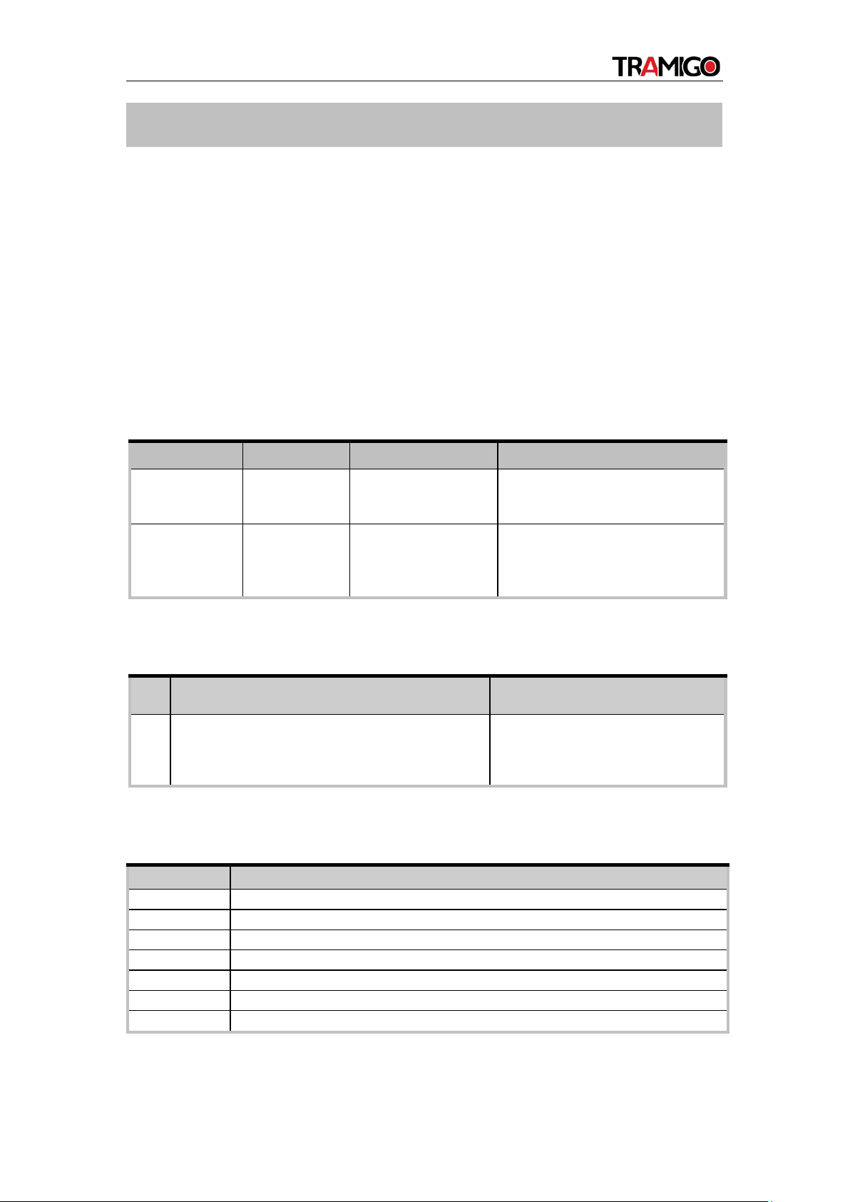
2.3. Parts List
Table 5. IQL 4G Vehicle Tracker Parts List
Name
Picture
Description
IQL 4G VEHICLE
TRACKER Locator
90mm*55mm*13mm
EGPRS/LTE Cat-M1/LTE
Cat-NB1/GNSS Tracker
User Cable
IQL 4G Vehicle Tracker
standard cable
Charger & USB
Cable(Optional)
To supply power and
configurethe
device
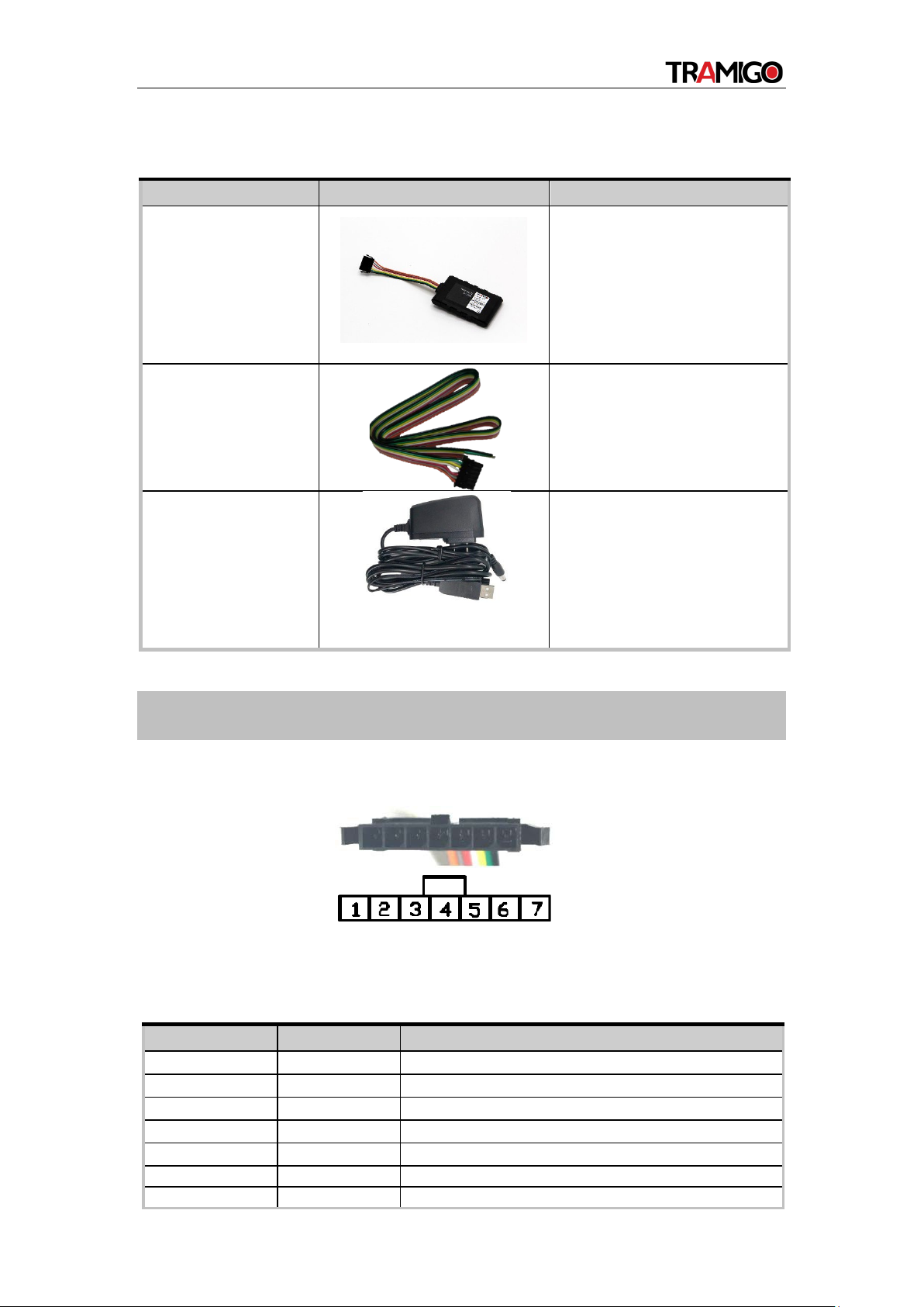
The IQL 4G VEHICLE TRACKER has a 7-pin interface connector. It contains the
connections for power, and I/O. Thesequence and description of the connector are shown
in the following figure:
Figure 4. 7-pin Connector of the IQL 4G
VEHICLE TRACKER Table 6. Description
of 7-pin Connections
3. Interface Definition
Index Description Comment
1
RXD
UART RXD; TTL
2
TXD
UART TXD; TTL
3
VIN
External DC power input, 8-32V
4
IGN
Ignition input, positive trigger
5
OUT1/IN1
Digital output/input; Open drain,150mA max
6
OUT2
Open drain, 150mA max
7
GND
GND
IQL 4G VEHICLE TRACKER USER MANUAL
8
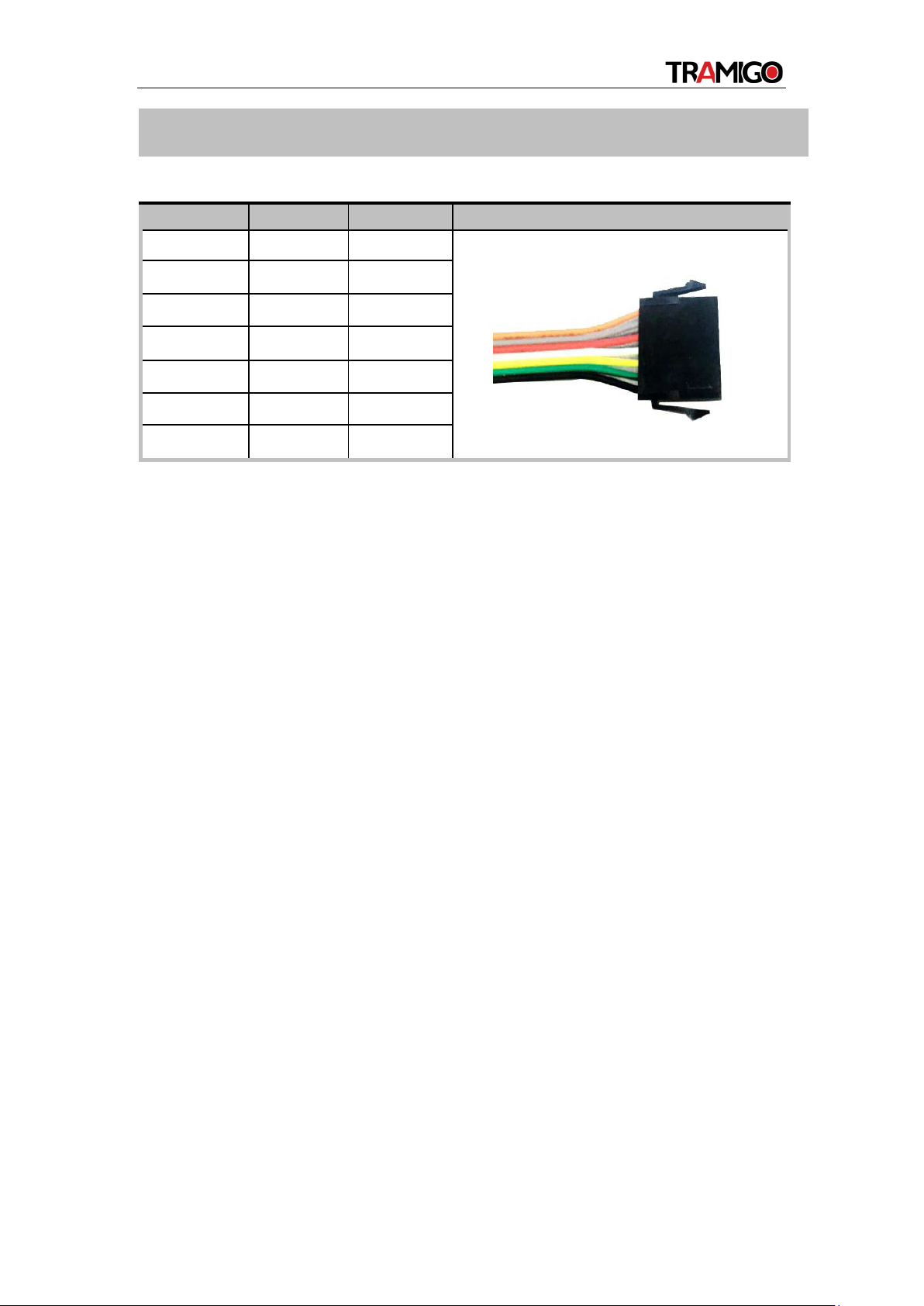
Table 7. IQL 4G VEHICLE TRACKER Device Cable Color Definition
Definition
Color
Pin No.
Cable
RXD Orange 1
TXD Gray 2
VIN Red 3
IGN White 4
OUT1/IN1 Yellow 5
OUT2 Green 6
GND Black 7
4. IQL 4G VEHICLE TRACKER Series Device Cable Color

IQL 4G VEHICLE TRACKER USER MANUAL
9
5.1. Switching on the Backup Battery
To use the IQL 4G VEHICLE TRACKER backup battery, the switch must be at the ON
position. The switch and theON/OFF position are shown as below.
Figure 7. Switch ON/OFF Position
Note:
1. The switch must be at the “OFF” position when the IQL 4G VEHICLE TRACKER is being
shipped on an aircraft.
2. When the switch is at the “OFF” position, the battery cannot be charged or discharged.
5.2. Power Supply Connection
VIN (pin 3)/GND (pin 7) are the power input pins. The input voltage range for this device
is from 8V to 32V. The device is designed to be installed in vehicles that operate on
12V/24V systems without the need for external transformers.
DC Power GND
Figure 8. Typical Power Connection
5.3. Ignition Detection
IGN (pin 4) is used for ignition detection. It is recommended to connect this pin to the
“RUN”position of the vehicle ignition switch as shown below.
An alternative to connect to the ignition switch is to find a non-permanent power source
that isonly available when the vehicle is running. For example, the power source for the
OFF
ON
5. Getting Started

IQL 4G VEHICLE TRACKER USER MANUAL
10
FM radio.
IGN signal can be configured to transmit information to the backend server when
ignition is onand enter power saving mode when ignition is off.

IQL 4G VEHICLE TRACKER USER MANUAL
11
Table 8. Electrical Characteristics of Ignition Detection
Logical State
Electrical Characteristics
Active
5.0V to 32V
Inactive
0V to 3V or Open loop
Figure 9. Typical Ignition Detection
5.4. Digital Output/Input
OUT1/IN1 (pin 5) is a digital Output/Input on IQL 4G VEHICLE TRACKER. It is of open
drain type and the maximum drain current is 150mA. The OUT1/IN1 (pin 5) can be used
either as a digital output or a (positive and negative trigger) digital input.
Figure 10. Digital Output Internal Drive Circuit
Table 9. Electrical Characteristics of Digital
Output
Logical State Electrical Characteristics
Enable <1.5V @150mA
Disable Open drain
IQL 4G VEHICLE TRACKER USER MANUAL
12
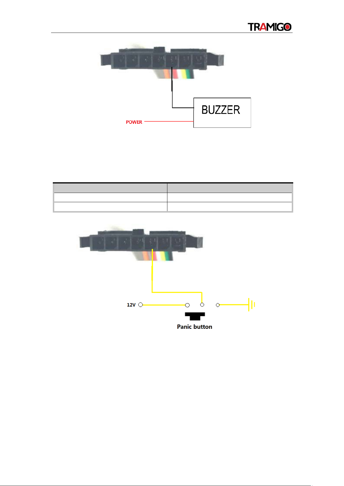
Figure 11. Typical Connection with a Buzzer as Digital
OutputTable 10. Electrical Characteristics of Digital
Input
Logical State
Electrical Characteristics
Active
0V to 0.8V
Inactive
Open loop
The following shows the recommended connection of a digital input.
Figure 12. Typical Digital Input Connection
IQL 4G VEHICLE TRACKER USER MANUAL
13
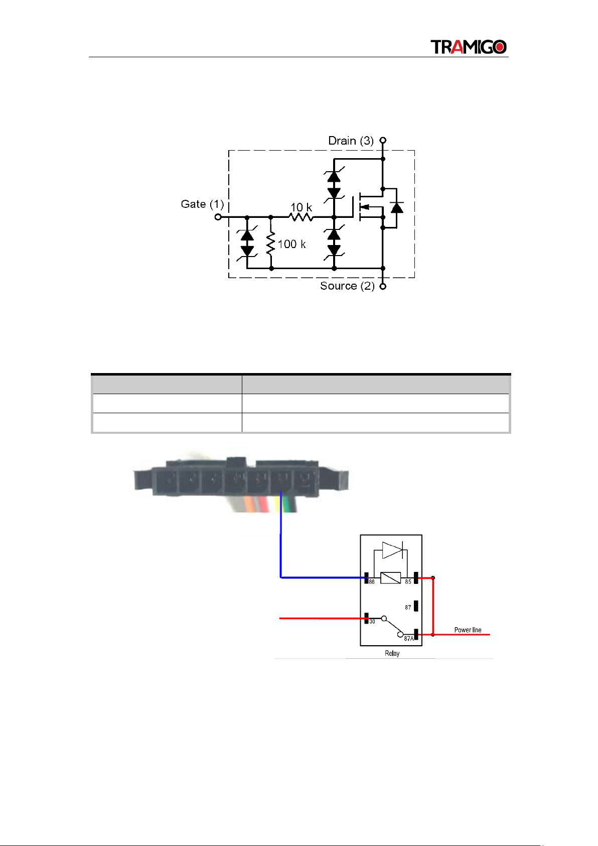
5.5. Digital Output
There is a digital output (pin 6) on IQL 4G VEHICLE TRACKER. It is of open drain type
and the maximum drain current is 150mA.
Figure 13. Digital Output Internal Drive Circuit
Table 11. Electrical Characteristics as Digital
Outputs
Logical State
Electrical Characteristics
Enable
<1.5V @150mA
Disable
Open drain
Figure 14. Typical Connection with a Relay
Warning: Many modern relays come with a flyback diode pre-installed internal to the relay
itself.If the relay has this diode, ensure the relay polarity connected is properly used. If this
diode is not internal, it should be added externally. A common diode such as a 1N4004 will
work in most circumstances.
IQL 4G VEHICLE TRACKER USER MANUAL
14
Firmly install the device to a reliable surface to prevent falling off.
Make the side with antenna face sky to have better signal reception.
Do not install the device under metal surface or in enclosed environments
havingdifficulty in getting GPS and network signal.
7.1. Troubleshooting
Problem
Possible Reason
Solution
After the device is turned
on, the CEL LED always
flashes quickly.
The signal is too weak.
The
device isn’t registered to
thenetwork.
Move the device to a place
withgood network coverage.
Messages can’t
be
reported to the
backend
server by network.
APN is not right.
Ask the network operator for
the right APN.
The IP address or port of
thebackend server is
wrong.
Make sure the IP address for
thebackend server is an
identified
address in the internet.
There is no response
from
UART when the device is
configured by using
UART.
The port is not ready or
thedevice is not powered
on.
Please check the port and the
device to ensure they
areworking properly.
The device can’t get
GPSfix.
The GPS signal is weak.
Move the device to a place
under open sky.
It is better to make the side
with antenna face the sky.
6.Installation Precautions
7.Troubleshooting and Safety Info

IQL 4G VEHICLE TRACKER USER MANUAL
15
Drop-down menu for single and multiple group or devices found on the list windowpane.
8. How to add the device to Tramigo Cloud
Found at the right of search bar.
a. Add Device
Option to add device on the cloud in a group or
individual. You can indicate the type of Tramigo
product to add and it will automatically send
Owner registration, timezone settings command
upon saving.
b. Add Device Group
Let you add Group/Folder Name and its
description (optional)
c. Delete Selected Devices
Using check boxes, you can delete individual or multiple devices that
are not needed anymore in the list.
d. Delete Selected Devices Groups
Using again check boxes, you can delete one or more folders/device
group that are not needed anymore.
e. Select All
Toggle to select all device and device group in the list view pane.
f. Unselect All
Toggle to deselect all checked device and device group in the list view pane.
i. Device Group Options
Button found at the right of Device Group Name,
lets you Delete the device group or Edit the
device group name and description
ii. Device List Option
Button found at the right of Device Name, lets you Send
Command, adjust Alert Settings, Delete the device, or Edit
the device name and description

IQL 4G VEHICLE TRACKER USER MANUAL
16
9. How to add the device to Tramigo App
a. Open mobile application
Go to Tramigo mobile application using Android OS or Apple IOS. At the front page
you can see plus icon.
b. Add Device
Tap on the plus icon and write in mandatory* information. IMEI number can be found
on the device’s sticker.
c. Ready to go
After everything is done, click add device and you can start tracking!
10. Safety Info
•Do not disassemble the device by yourself.
•Do not put the device in over heated too humid place, and avoid exposure
to direct sunlight. Too high temperature will damage the device or even
cause battery explosion.
•Do not use the device on the airplane or near medical equipment.
Currently, no external accessory is supported.
11. Appendix: Supported Accessories
This manual suits for next models
1
Table of contents
Other Tramigo GPS manuals

Tramigo
Tramigo T22 User manual

Tramigo
Tramigo T22 User manual

Tramigo
Tramigo T23 Fleet User manual

Tramigo
Tramigo T22 User manual

Tramigo
Tramigo T23 Fleet User manual

Tramigo
Tramigo T21 User manual

Tramigo
Tramigo T23 Track User manual

Tramigo
Tramigo T23 Fleet User manual

Tramigo
Tramigo T23 Fleet User manual

Tramigo
Tramigo T22 User manual


