manuals.online logo
Brands
  1. Home
  2. •
  3. Brands
  4. •
  5. Trane
  6. •
  7. Control Unit
  8. •
  9. Trane CNT06197 Assembly instructions

Trane CNT06197 Assembly instructions

RS-485 Replacement
Board
CNT06197 is a replacement board kit for the RS-485
hydronic heat control
INSTALLER'S
GUIDE
IMPORTANT—This Document is customer property and is to remain with this unit. Please return to service information
pack upon completion of work.
© 2012 Trane
ALL phases of this installation must comply with
NATIONAL, STATE AND LOCAL CODES
18-GJ59D1-2
11/12
Models:
CNT06197
Section 1. General Information
The CNT06197 kit is for use with the BAYWV 05, 07, 08 hy-
dronic heating coils. The kit is also used with BAYWA 05, 07,
08, and 11 series hydronic heating coils that have the RS-485
control.
Check the components received for damage. Report any de-
fects or shortages to the transportation company immediately.
Section 2. Safety Considerations
2.1 WARNINGS
IMPORTANT: Read this manual carefully before attempting to install,
operate, or perform maintenance on this hydronic coil. Installation,
service, and maintenance should be performed by qualified technicians
only.
NOTE: “Warnings” and “Cautions” appear at appropriate places in this
manual. Read these carefully. Your personal safety and the proper
operation of this heating product require that you follow them carefully.
The manufacturer assumes no liability for installations or services
performed by independent dealers.
Safety signal words are used to designate a degree or level of serious-
ness associated with a particular hazard. The signal words for safety
markings are WARNING and CAUTION.
▲WARNING
!
WARNING indicates a potentially hazardous situation which, if not
avoided, could result in property damage, death or serious personal
injury.
▲CAUTION
!
CAUTION indicates a potentially hazardous situation which, if not
avoided, may result in minor or moderate injury. It is also used to alert
against unsafe practices and hazards involving only property damage.
▲
WARNING
!
THE INFORMATION IN THIS GUIDE IS FOR USE BY INDIVIDUALS
HAVING ADEQUATE ELECTRICAL AND MECHANICAL BACK-
GROUND. ANY ATTEMPTS, BY UNQUALIFIED PERSONS, AT
PLUMBING, INSTALLING OR REPAIRING A HYDRONIC SYSTEM
OR CENTRAL AIR CONDITIONING PRODUCT COULD RESULT IN
PROPERTY DAMAGE, SEVERE PERSONAL INJURY OR DEATH. THE
MANUFACTURER OR SELLER CANNOT BE RESPONSIBLE FOR THE
INTERPRETATION OF THIS INFORMATION, NOR CAN IT ASSUME
ANY LIABILITY IN CONNECTION WITH ITS USE.
▲
WARNING
!
ELECTRICAL HAZARD!
DISCONNECT ALL ELECTRICAL POWER, INCLUDING REMOTE
DISCONNECTS BEFORE INSTALLING OR SERVICING. FOLLOW
PROPER LOCKOUT/TAGOUT PROCEDURES TO ENSURE THE
POWER CAN NOT BE INADVERTENTLY ENERGIZED. FAILURE TO
FOLLOW THIS WARNING COULD RESULT IN SERIOUS PERSONAL
INJURY, DEATH, OR PROPERTY DAMAGE.
Page 2
INSTALLER'S GUIDE
SAFETY HAZARD!
All joints must be leak free.
▲CAUTION
!
SAFETY HAZARD! Sharp Edge Hazard. Be careful of sharp
edges on equipment or any cuts made on sheet metal while install-
ing or servicing. Personal injury may result.
▲CAUTION
!
▲
WARNING
!
SAFETY HAZARD!
THIS HYDRONIC COIL MUST ONLY BE USED IN NON-POTABLE
CLOSED WATER SYSTEMS. FAILURE TO FOLLOW THIS WARN-
ING COULD RESULT IN SERIOUS PERSONAL INJURY, DEATH, OR
PROPERTY DAMAGE.
▲
WARNING
!
HIGH PRESSURE HAZARD!
MAXIMUM ENTERING WATER TEMPERATURE IS 180°F. WATER TEM-
PERATURES EXCEEDING 180°F COULD CAUSE A HIGH PRESSURE
BURST. FAILURE TO FOLLOW THIS WARNING COULD RESULT IN
SERIOUS PERSONAL INJURY, DEATH, OR PROPERTY DAMAGE.
▲
WARNING
!
SCALD HAZARD!
THIS SYSTEM CONTAINS HOT WATER AND OPERATES UNDER
PRESSURE. WATER TEMPERATURES ABOVE 125°F CAN INSTANT-
LY CAUSE SEVERE BURNS OR DEATH.
USE CAUTION WHEN SERVICING THIS EQUIPMENT. ALLOW SUF-
FICIENT TIME FOR THE WATER TO COOL BEFORE OPENING THE
SYSTEM DRAIN. FAILURE TO FOLLOW THIS WARNING COULD
RESULT IN SERIOUS PERSONAL INJURY, PROPERTY DAMAGE, OR
DEATH.
▲
WARNING
!
LEAK HAZARD!
IF THE HYDRONIC COIL HAS A LEAK, USE CAUTION WHEN SERVIC-
ING THIS EQUIPMENT. THOROUGHLY WIPE OFF EXCESS WATER
FROM ALL COMPONENTS AND ALLOW ADEQUATE TIME FOR
THE COMPONENTS TO DRY COMPLETELY BEFORE SERVICING
SYSTEM.
FAILURE TO FOLLOW THIS WARNING COULD RESULT IN SERIOUS
PERSONAL INJURY, PROPERTY DAMAGE, OR DEATH.
2.2 CAUTIONS
Page 3
INSTALLER'S GUIDE
D156015G01 CNT06197
HH CONTROL VXX
P4
P5
P3
P1
123
D156015G01
FAULT
STAT US
UNIT
Section 3. Hydronic Heat Control Board
HHC Board
LEDs
HHC Board
Dip Switches
P1 - Factory Low Voltage
Connection
P4 - Field Low Voltage Connection
IMPORTANT: Line voltage must not be applied.
NOTE: P4 relay contacts are not powered and
rated for 1.0 Amp at 24 VAC.
P5 - Water Sensor
Page 4
INSTALLER'S GUIDE
STEP 4 - Low Voltage board Dip Switches - DS1 dip
switches are not factory set. Adjustments must be
made per the table.
Dip
Switches
D156015P01 CNT06197
HH CONTROL VXX
P4
P5
P3
P1
123
D156015P01
FAULT
STATUS
UNIT
123
HHC DIP SWITCH SETTINGS
COIL MODEL / AHU MODEL S1-1 S1-2 S1-3
BAYWAAA05 w/*AM7A0A24, BAYWAAA05 w/*AM8A0A24
BAYWAAA05 w/TAMGA0A24 OFF OFF ON
BAYWABB07 w/*AM7A0B30, BAYWABB07 w/*AM8A0B30 OFF ON OFF
BAYWACC08 w/*AM7A0C36, BAYWACC08 w/*AM7A0C36
BAYWACC08 w/TAMGA0C36 OFF ON ON
BAYWACC08 w/*AM7A0C42, BAYWACC08 w/*AM8A0C42 ON OFF OFF
BAYWACC08 w/*AM7A0C48, BAYWACC08 w/*AM7A0C48
BAYWACC08 w/TAMGA0C48 ON OFF ON
BAYWACC08 w/*AM7A0C60, BAYWACC08 w/*AM7A0C60
BAYWACC08 w/TAMGA0C60 ON ON OFF
BAYWACC11SC1A w/*AM7A0C60
BAYWACC11SC1A w/TAMGA0C60
ON ON ON
* May be "A" or "T"
HHC
Fault LED Description
OFF Nofault
1 Internalcommunicationerror
2 Watertempisat38Forlower
3 Watertempsensorisshorted
4 Watertempsensorisopen
5Configurationerror(1)
6 Heatdemanderror
1) Confirm heater model and dip switch configuration
NOTES:
HHC STATUS CODES (GREEN LED)
HHC FAULT CODES (RED LED)
HHC UNIT LED (BLUE LED)
HHC STATUS LED
1 per second
2 per second
Description
Standby or idle (see note)
Heating demand is present
UnitLED
1Flash
Rapid
Off NoPower
Description
Normal(1flashevery4seconds)
CommunicationBusyError(2flashespersecond)
SOLIDON CommunicationscannotbeestablishedwiththeAFC
Section 5. Alert LED Codes
Section 4. Dip Switch Settings
D156015P01 CNT06197
HH CONTROL VXX
P4
P5
P3
P1
SW1
D156015P01
FAULT
STAT US
UNIT
FAULT
STATUS
UNIT
Since the manufacturer has a policy of continuous product and product data im-
provement, it reserves the right to change design and specification without notice.
Trane
6200 Troup Highway
Tyler, TX 75707

Other Trane Control Unit manuals

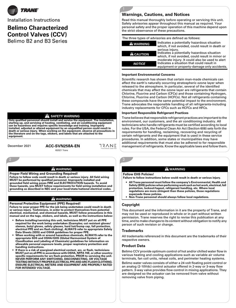
Trane TZON1050AC52ZA User manual

Trane

Trane TZON1050AC52ZA User manual

Trane TR200 MCB 105 User manual

Trane

Trane TR200 MCB 105 User manual

Trane UNT-SVU011C Series Quick start guide

Trane

Trane UNT-SVU011C Series Quick start guide

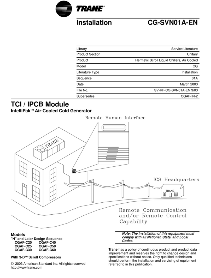
Trane CG-SVN01A-EN User manual

Trane

Trane CG-SVN01A-EN User manual

Trane Tracer Summit Mounting instructions

Trane

Trane Tracer Summit Mounting instructions

Trane AYSVPANL0022AA Series Assembly instructions

Trane

Trane AYSVPANL0022AA Series Assembly instructions

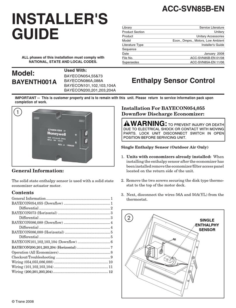
Trane BAYENTH001A Assembly instructions

Trane

Trane BAYENTH001A Assembly instructions

Trane BAS-SVN213A-EN User manual

Trane

Trane BAS-SVN213A-EN User manual

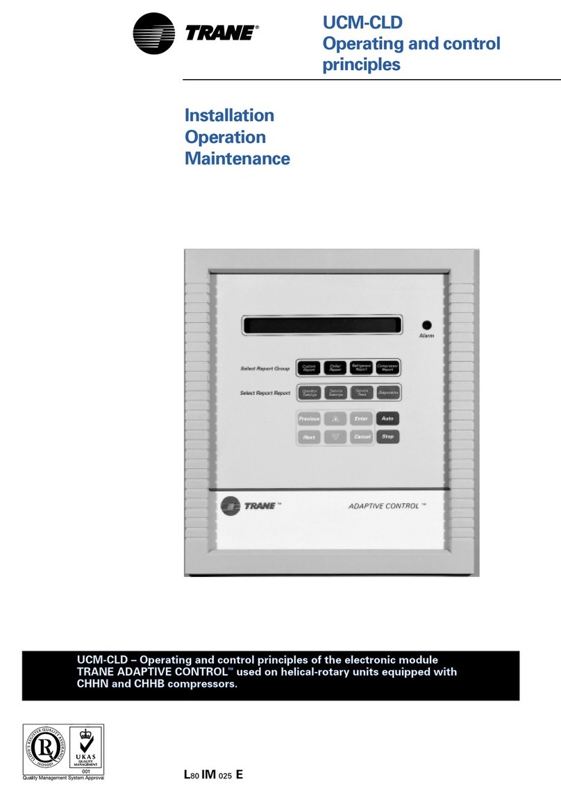
Trane ADAPTIVE CONTROL UCM-CLD Owner's manual

Trane

Trane ADAPTIVE CONTROL UCM-CLD Owner's manual

Trane RTHC-SVN02C-EN User manual

Trane

Trane RTHC-SVN02C-EN User manual

Trane ComfortLink II XL 850 User manual

Trane

Trane ComfortLink II XL 850 User manual

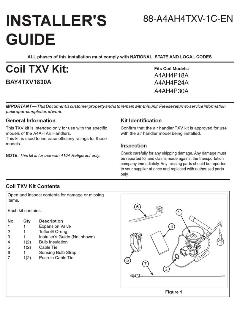
Trane BAY4TXV1830A Assembly instructions

Trane

Trane BAY4TXV1830A Assembly instructions

Trane TRACER SUMMIT BMTX-SVU01B-EN User manual
Trane

Trane TRACER SUMMIT BMTX-SVU01B-EN User manual

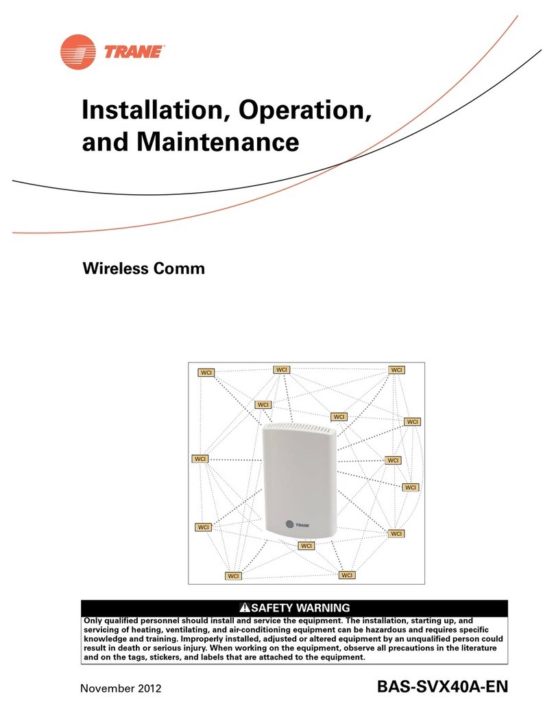
Trane Wireless Comm Installation and operating instructions
Trane

Trane Wireless Comm Installation and operating instructions

Trane PM014 Installation and operating instructions

Trane

Trane PM014 Installation and operating instructions

Trane VAV User manual

Trane

Trane VAV User manual

Trane 700 User manual

Trane

Trane 700 User manual

Trane VariTrane Owner's manual

Trane

Trane VariTrane Owner's manual

Trane XL824 User manual

Trane

Trane XL824 User manual

Trane Tracer MP503 Installation and operating instructions

Trane

Trane Tracer MP503 Installation and operating instructions

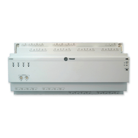
Trane Tracer XM30 Installation and operating instructions

Trane

Trane Tracer XM30 Installation and operating instructions

Trane Belimo B2 Series User manual

Trane

Trane Belimo B2 Series User manual
Trane MERCURY EDAB 1105A Quick start guide

Trane

Trane MERCURY EDAB 1105A Quick start guide

Trane TR200 MCB 101 User manual

Trane

Trane TR200 MCB 101 User manual

Popular Control Unit manuals by other brands

Comelit VEDOGSM4G Technical manual

Comelit

Comelit VEDOGSM4G Technical manual

quiko QK-CE220WRL quick start guide

quiko

quiko QK-CE220WRL quick start guide

dixell ichill IC260L user manual

dixell

dixell ichill IC260L user manual

Microchip Technology RN4020 manual

Microchip Technology

Microchip Technology RN4020 manual

ProSoft Technology MVI69E-LDM-MQTT quick start guide

ProSoft Technology

ProSoft Technology MVI69E-LDM-MQTT quick start guide

Task Force Tips Max Flip Tip2 manual

Task Force Tips

Task Force Tips Max Flip Tip2 manual

Lauda LRZ 914 Operation manual

Lauda

Lauda LRZ 914 Operation manual

ICP DAS USA DS-2200 Series quick start

ICP DAS USA

ICP DAS USA DS-2200 Series quick start

PR electronics 9410 Series manual

PR electronics

PR electronics 9410 Series manual

Innovative Electronics EMS 30 A H-Bridge quick start

Innovative Electronics

Innovative Electronics EMS 30 A H-Bridge quick start

Phason iWire Flex Radio installation guide

Phason

Phason iWire Flex Radio installation guide

Pentair FLECK 4600 SXT user guide

Pentair

Pentair FLECK 4600 SXT user guide

Burkert 6511 operating instructions

Burkert

Burkert 6511 operating instructions

UNICORECOMM UM482 user manual

UNICORECOMM

UNICORECOMM UM482 user manual

Aritech ACA 001 Installation sheet

Aritech

Aritech ACA 001 Installation sheet

Burkert 5281 operating instructions

Burkert

Burkert 5281 operating instructions

Siemens SOAM manual

Siemens

Siemens SOAM manual

Ai-Thinker Technology Ra-01SC manual

Ai-Thinker Technology

Ai-Thinker Technology Ra-01SC manual

manuals.online logo
manuals.online logoBrands
  • About & Mission
  • Contact us
  • Privacy Policy
  • Terms and Conditions

Copyright 2025 Manuals.Online. All Rights Reserved.