manuals.online logo
Brands
  1. Home
  2. •
  3. Brands
  4. •
  5. TriangleTube
  6. •
  7. Control Unit
  8. •
  9. TriangleTube PRESTIGE TriMax PTRKIT205 User manual

TriangleTube PRESTIGE TriMax PTRKIT205 User manual

PRESTIGE TriMax Control
and/or Display Module Replacement
1
Kit Part umber:
- PTRKIT205 - TriMax Control Module
(PT 60/110, 175, PTE 110)
- PTRKIT206 - TriMax Control Module
(PT250/399)
-PTRKIT207 - TriMax Display Module
Parts List (Fig.1)
1 - Control Module (PT KIT205) - Item 1
2 - Display Module (PT KIT207) - Item 2
Recommended Tools:
- Phillips Screwdriver
Indicates a potentially hazardous situation
which, if ignored, can result in serious
injury or substantial property damage.
For your safety, turn off electrical power
supply at service panel before proceeding to
avoid possible electrical shock hazard.
Failure to do so can cause severe personal
injury or death.
For your safety, the boiler may be extremely
hot. Ensure the boiler has properly cooled
prior to servicing. Failure to do so can cause
severe personal injury.
Indicates special instructions on installa-
tion, operation or maintenance, which are
important to equipment but not related to
personal injury hazards.
Failure to follow instructions below can
result in severe personal injury or damage if
ignored.
• Instructions are for a qualified installer/
service technician.
• Read all instructions before proceeding.
• Follow instructions in proper order.
These part kits PTRKIT205, PTRKIT206
and PTRKIT207 can only be used on
Prestige Boilers with serial numbers begin-
ning with PT.
WARNING
WARNING
NOTICE
WARNING
NOTICE
WARNING
1
2
Fig. 1: PRESTIGE Solo Control
Pres ige_TriMax_Con rol_Display_Module_DCR639 1/14/14 9:45 AM Page 1
PRESTIGE TriMax Control
and/or Display Module Replacement
Removal of the Prestige TriMax Control Module
and Display Module
Prior to replacing the control module and/or dis-
play module, it is important to access and docu-
ment the boiler’s settings. This will ensure any
settings revised from factory defaults are trans-
ferred to the new module(s). Use Table 1 to
record the existing settings. Do not revise any
settings when recording settings.
1. To access the parameter screen, press the round
installer button as shown in Fig. 2.
2. Enter the installer access code “054” by using
the LEFT and RIGHT buttons to select a digit
and the UP and DOW buttons to change the
digit. Press the OK button to enter the access
code.
3. Press the OK button while the CH & DHW
Settings icon is highlighted.
4. Press the OK button while the CH Settings
icon is highlighted.
5. Press the UP and DOW buttons to scroll thru
the various settings.
6. ecord all CH Settings in Table 1. Once com-
pleted, press the RIGHT button to highlight
the Previous Screen icon , then press the OK
button.
NOTICE
2
Installer
Button
Fig. 2: Trimax avigation Buttons
ENTER INSTALLER
ACCESS CODE
[0]XX
CH Settings
CH & DHW Settings
Heating Settings
Heating Operation
Demand
Absolute Max CH Setpoint
CH1 Maximum Setpoint
CH1 Minimum Setpoint
Reset Curve Coldest Day
Enabled
Switch & Setpoint
188ºF
180ºF
120ºF
0ºF
Heating Operation
Enabled
Pres ige_TriMax_Con rol_Display_Module_DCR639 1/14/14 9:45 AM Page 2
PRESTIGE TriMax Control
and/or Display Module Replacement
3
7. Press the RIGHT button to highlight the DHW
Settings icon then press the OK button.
8. Press the UP and DOW buttons to scroll thru
the various settings and record all DHW
Settings in Table 1. Once completed, press the
RIGHT button to highlight the Previous Screen
icon , then press the OK button.
9. Press the DOW button to highlight the Boiler
Settings icon if present icon , then press the
OK button.
10. Press the UP and DOW buttons to scroll thru
the various settings and record all Boiler
Settings in Table 1. Once completed, press the
RIGHT button to highlight the Previous Screen
icon , then press the OK button.
Perform the following steps if the Prestige is part
of a Cascade System or the System Temperature
Sensor is being used on a single Prestige.
11. Press the RIGHT then DOW buttons to high-
light the Previous Screen icon , then press
the OK button.
12. Press the RIGHT then DOW buttons to high-
light the Cascade icon , then press the OK
button.
13. Press the RIGHT button to highlight the
Cascade Settings icon , then press the OK
button.
14. Press the UP and DOW buttons to scroll thru
the various settings, and record all Cascade
Settings in Table 1.
Removal of Trimax Control Module.
1. Turn the electrical power “OFF”.
2. emove the front jacket panel by removing the
thumb screw along the upper edge of the unit.
Lift it up and tilt back slightly to remove the
front panel.
3. Slide left and right tabs of control panel inward
and lower control panel. See Fig. 3.
4 . Pull the retaining tabs on top of the rear cover to
remove the rear control box cover. See Fig. 4.
5. Disconnect the ignition cable by grasping the
ignition terminal and pulling firmly upwards from
the back of the control module. Use care not to
damage the ignition cable or ignition terminal.
NOTICE
DHW Settings
DHW Settings
DHW Operation
Demand
Boiler DHW Setpoint
DHW Storage Setpoint
DHW On Differential
DHW StorageAdder
Enabled
Switch
186ºF
140ºF
6ºF
46ºF
DHW Operation
Enabled
Retaining
Tab
Retaining
Tab
Panel
will pivot
downward
Fig. 3: Opening & Lowering Control Panel
Pres ige_TriMax_Con rol_Display_Module_DCR639 1/14/14 9:45 AM Page 3
PRESTIGE TriMax Control
and/or Display Module Replacement
4
6. emove all (8) Molex wiring connectors from
the Control Module. Support Trimax Control
Module with one hand while removing individ-
ual Molex connectors. Press tabs on Molex
plugs for quick release. See Fig. 5.
7. emove the 2 screws securing the Control
Module into the enclosure and remove the
Control Module. Do not discard the Trimax
Control Module. See Fig. 6.
Go to step 15 if one only wants to remove the
Trimax Control Module. Proceed to step 8 if the
Trimax Display Module must also be removed.
Removal of Trimax Display Module
The Trimax Control Module must always be
removed prior to removing the Trimax Display
Module.
8. emove Molex connectors 1 thru 3 from the
Display Module as shown in Fig. 7.
9. emove 6 screws securing the Trimax Display
Module to the enclosure.
10. emove Molex connectors 4 thru 6 from the
display module as shown in Fig. 7.
11. Carefully remove the Trimax Display Module.
Installation of Trimax Display Module
12. econnect Molex connectors 4 thru 6 to the
new display module as shown in Fig. 7.
Connectors are designed to fit only into its
respective mating connector.
NOTICE
NOTICE
Retaining Tabs
Fig. 4: Control Box Assembly
1
2
6
5
43
7
8
Fig. 5: Control Module Molex Connections
Mounting
screw
location
Mounting
screw
location
Fig. 6. Control Module Mounting
Pres ige_TriMax_Con rol_Display_Module_DCR639 1/14/14 9:45 AM Page 4
PRESTIGE TriMax Control
and/or Display Module Replacement
5
13. Mount the new Trimax Display Module into the
enclosure using existing screws. Tighten all
(6) screws properly to secure the Display
Module.
14. econnect remaining Molex connectors in the
proper positions. Connectors are designed to fit
only into its respective mating connector.
Installation of Trimax Control Module
15. Mount the Trimax Control Module into the
enclosure by positioning the board onto the pro-
truding pins.
16. Use existing mounting screws to secure the
Control Module.
17. econnect the 8 Molex connectors to proper
positions as shown in Fig. 5. Each connector is
designed to fit only in its respective mating
connector.
18. econnect ignition cable onto the Control
Module ignition connector.
19. Place the rear cover in place and lock in the top
retaining tabs.
20. Tilt control panel assembly upward and lock
sliding tabs in place.
21. emount the front jacket panel to the boiler.
22. Turn power to the unit “ON” and return the
boiler to service.
23. eturn to page 2 and enter settings recorded in
Table 1 back into the Trimax control.
Prestige Excellence units require setting Prestige
Model to Excellence and DHW Demand Type to
Sensor.
If the Prestige is in a Cascade System, Cascade
Autodetection must be performed after replac-
ing a Control or Display Module.
NOTICE
NOTICE
1
2
3
4
5
6
Fig. 7. Display Module Mounting
Pres ige_TriMax_Con rol_Display_Module_DCR639 1/14/14 9:45 AM Page 5
PRESTIGE TriMax Control
and/or Display Module Replacement
6
Table 1: TriMax Settings
evised Date: 1/14/14 2011-55 Prestige_TriMax Control &/or Display Module epl
DOMESTIC SETTI G FACTORY DEFAULT MI IMUM SETTI G MAXIMUM SETTI G EXISTING SETTING
DHW Operation Enabled
Demand Switch
Boiler DHW Setpoint 186°F [86°C] 96°F [35°C] 188°F [87°C]
DHW Storage Setpoint 140°F [60°C] 68°F [20°C] 150°F [65°C]
DHW On Differential 6°F [3°C] 4°F [2°C] 18°F [10°C]
DHW Storage Adder 46°F [25°C] 0°F [0°C] 54°F [30°C]
DHW Post Pump Time 1 minute OFF 30 minutes
DHW Priority Timeout OFF OFF 120 minutes
DHW Priority Enabled
DHW Call Blocking 0 minute 0 minute 30 minutes
DHW to CH Call Blocking 1 minute 0 minute 30 minutes
Antilegionella Function Disabled
HEATI G SETTI G FACTORY DEFAULT MI IMUM SETTI G MAXIMUM SETTI G EXISTING SETTING
Heating Operation Enabled
Demand Switch &
Outdoor Reset
Absolute Max CH Setpoint 188°F [87°C] 68°F [20°C] 188°F [87°C]
CH1 Maximum Setpoint 180°F [82°C] 68°F [20°C] 188°F [87°C]
CH1 Minimum Setpoint 120°F [49°C] 60°F [15°C] 188°F [87°C]
Reset Curve Coldest Day 0°F [-18°C] -30°F [-34°C] 50°F [10°C]
Reset Curve Warmest Day 64°F [18°C] 60°F [15°C] 78°F [25°C]
CH2 Circuit Enabled
CH2 Maximum Setpoint 140°F [60°C] 68°F [20°C] 188°F [87°C]
CH2 Minimum Setpoint 80°F [27°C] 60°F [15°C] 188°F [87°C]
Warm Weather Shutdown OFF OFF 78°F [25°C]
Pump Constant Circulation Disabled
CH Post Pump Time 1 minute OFF 20 minute
Freeze Protection Enabled
Frost Protection Setpoint -22°F [-30°C] -22°F [-30°C] 50°F [10°C]
Parallel Shift Value 0°F [0°C] 0°F [0°C] 144°F [80°C]
CH Call Blocking 1 minute 0 minute 30 minutes
System Pump CH1/CH2
CASCADE SETTI G FACTORY DEFAULT MI IMUM SETTI G MAXIMUM SETTI G EXISTING SETTING
Stage Delay 60 seconds 0 second 255 seconds
Minimum Firing Rate 30% 0% 100%
Maximum Firing Rate 398 MBH [117kW] 0 MBH [0kW] 869 MBH [255kW]
CH / DHW Boilers 0 0 6
Automatic Rotation Enabled
CH Proportional Gain 7 1 255
CH Integral Gain 245 1 255
DHW Proportional Gain 7 1 255
DHW Integral Gain 245 1 255
BOILER SETTI G FACTORY DEFAULT MI IMUM SETTI G MAXIMUM SETTI G EXISTING SETTING
Prestige Mode So o
Lockout Temperature 210°F [99°C]
Modbus Address 0=BCST 0 247
Pres ige_TriMax_Con rol_Display_Module_DCR639 1/14/14 9:45 AM Page 6

This manual suits for next models

2

Other TriangleTube Control Unit manuals
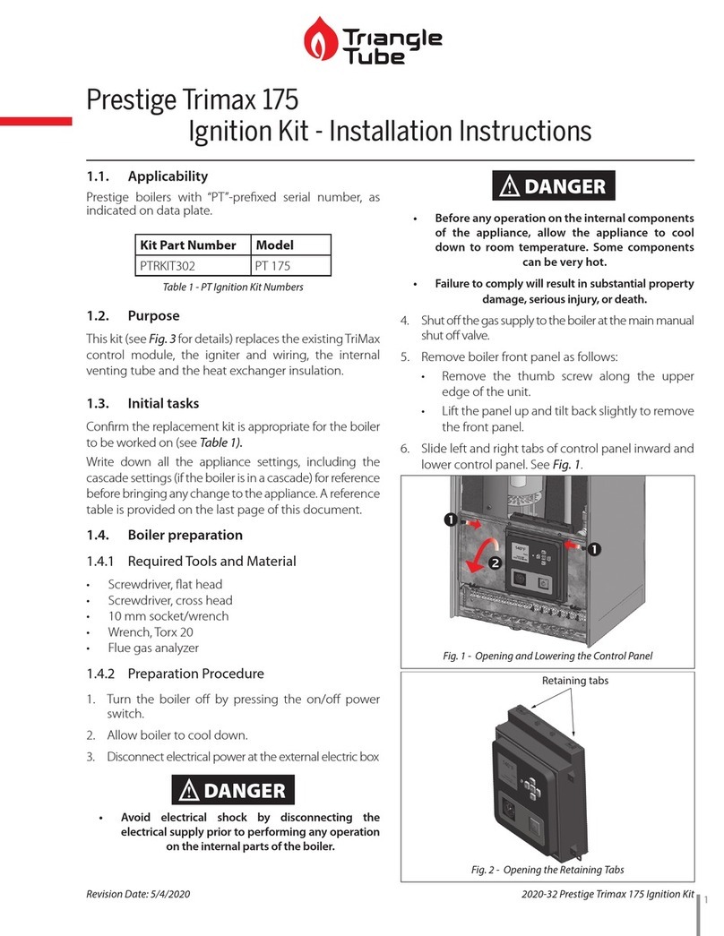
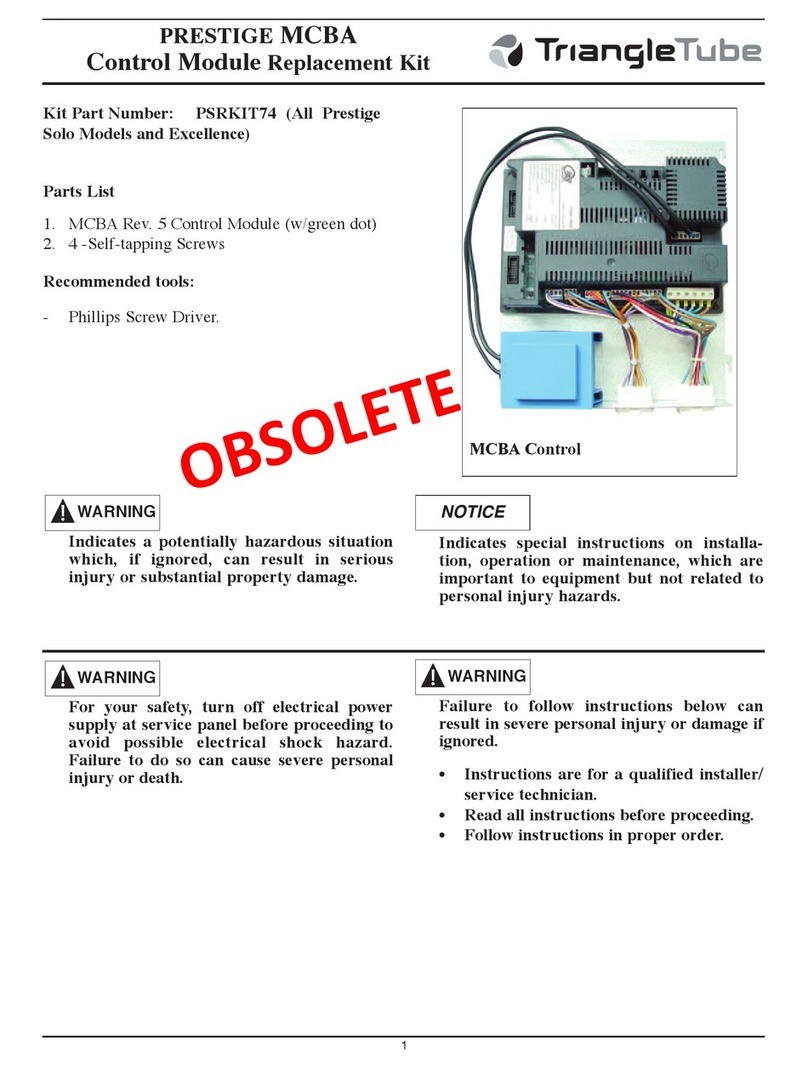
TriangleTube PSRKIT20 User manual

TriangleTube

TriangleTube PSRKIT20 User manual

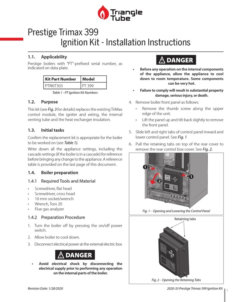
TriangleTube Prestige Trimax 399 User manual

TriangleTube

TriangleTube Prestige Trimax 399 User manual

TriangleTube Prestige Trimax 175 User manual
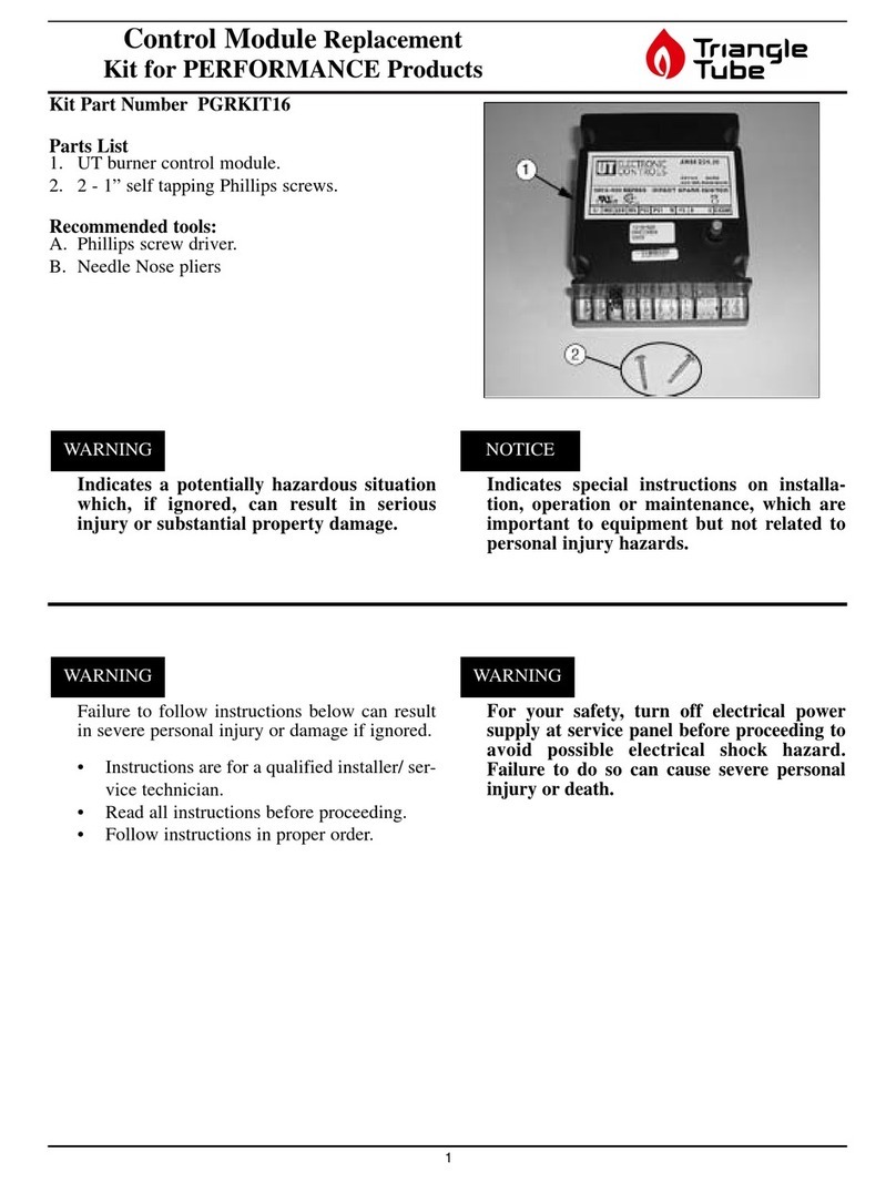
TriangleTube

TriangleTube Prestige Trimax 175 User manual

TriangleTube PSRKIT23 User manual

TriangleTube

TriangleTube PSRKIT23 User manual

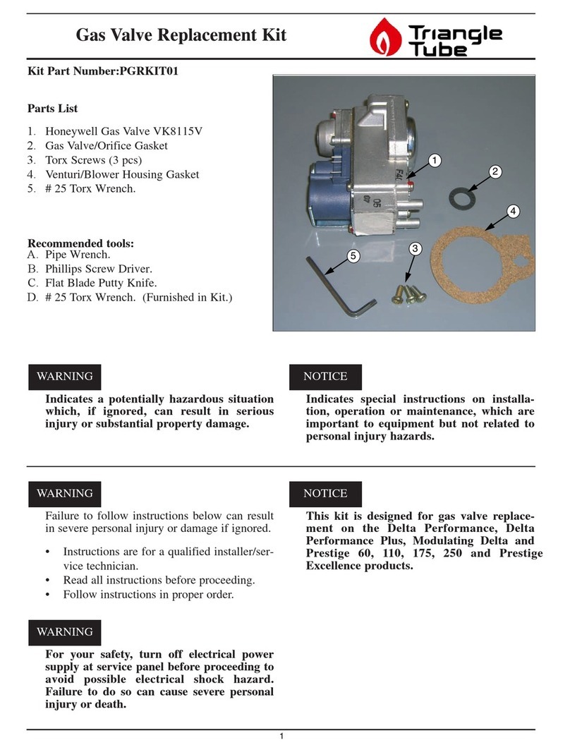
TriangleTube PGRKIT01 User manual

TriangleTube

TriangleTube PGRKIT01 User manual

TriangleTube PGRKIT16 User manual

TriangleTube

TriangleTube PGRKIT16 User manual
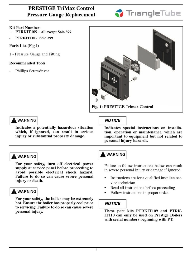
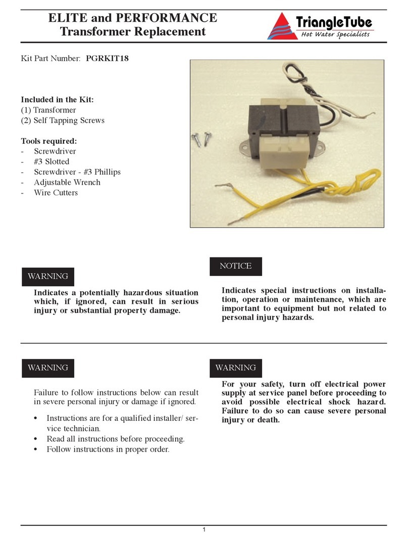
TriangleTube PGRKIT18 User manual

TriangleTube

TriangleTube PGRKIT18 User manual

TriangleTube INSRKIT06 User manual

TriangleTube

TriangleTube INSRKIT06 User manual

TriangleTube CHALLENGER CC 85 User manual

TriangleTube

TriangleTube CHALLENGER CC 85 User manual

TriangleTube PTRKIT111 User manual

TriangleTube

TriangleTube PTRKIT111 User manual

TriangleTube Optima Series Installation instructions

TriangleTube

TriangleTube Optima Series Installation instructions

TriangleTube PRESTIGE TriMax PTRKIT109 User manual
TriangleTube

TriangleTube PRESTIGE TriMax PTRKIT109 User manual

TriangleTube PTRKIT112 User manual

TriangleTube

TriangleTube PTRKIT112 User manual

TriangleTube PSRKIT74 User manual

TriangleTube

TriangleTube PSRKIT74 User manual
Popular Control Unit manuals by other brands

Innophase Talaria TWO Hardware user's guide

Innophase

Innophase Talaria TWO Hardware user's guide

AMX 8450-03 installation guide

AMX

AMX 8450-03 installation guide

Allen-Bradley Rockwell Automation 1734-4IOL user manual

Allen-Bradley

Allen-Bradley Rockwell Automation 1734-4IOL user manual

Festo CPX-FVDA-P2 Original instructions

Festo

Festo CPX-FVDA-P2 Original instructions

TLV SS1VA instruction manual

TLV

TLV SS1VA instruction manual

Samsung WEC8500 Operation manual

Samsung

Samsung WEC8500 Operation manual

Texas Instruments ADS1254 user guide

Texas Instruments

Texas Instruments ADS1254 user guide

adept technology R Series Instruction handbook

adept technology

adept technology R Series Instruction handbook

NI PXI-6653 user manual

NI

NI PXI-6653 user manual

AV-GAD AVG064 Installation and operation manual

AV-GAD

AV-GAD AVG064 Installation and operation manual

Emerson unidrive m Installation and operating manual

Emerson

Emerson unidrive m Installation and operating manual

Texas Instruments PCM1808EVM user guide

Texas Instruments

Texas Instruments PCM1808EVM user guide

Dover PSG BLACKMER AIR VALVE Installation, operation and maintenance instructions

Dover

Dover PSG BLACKMER AIR VALVE Installation, operation and maintenance instructions

Omron CJ1W-MA - REV 10-2008 Operation manual

Omron

Omron CJ1W-MA - REV 10-2008 Operation manual

Digi XTend vB DigiMesh XTP9B-DPM-001 user guide

Digi

Digi XTend vB DigiMesh XTP9B-DPM-001 user guide

ICP DAS USA tSG-3781B user manual

ICP DAS USA

ICP DAS USA tSG-3781B user manual

Regada DMS3 Setup

Regada

Regada DMS3 Setup

LEGRAND 0 676 97 manual

LEGRAND

LEGRAND 0 676 97 manual

manuals.online logo
manuals.online logoBrands
  • About & Mission
  • Contact us
  • Privacy Policy
  • Terms and Conditions

Copyright 2025 Manuals.Online. All Rights Reserved.