manuals.online logo
Brands
  1. Home
  2. •
  3. Brands
  4. •
  5. TriangleTube
  6. •
  7. Control Unit
  8. •
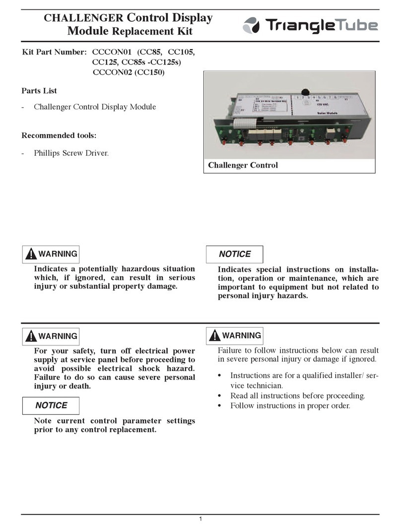
  9. TriangleTube PTRKIT112 User manual

TriangleTube PTRKIT112 User manual

Gas alve Replacement Kit
Prestige Solo 399
1
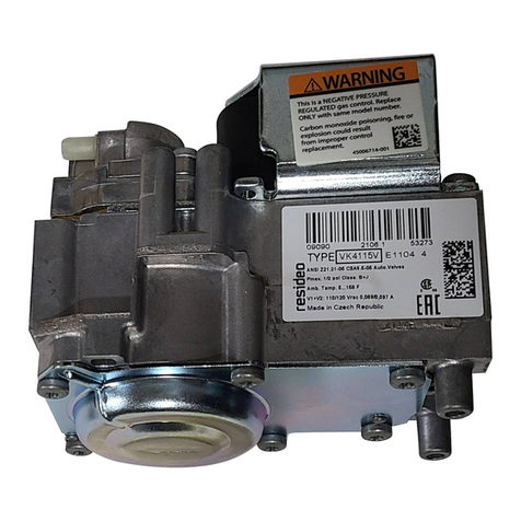
Kit Part Number: PTRKIT112
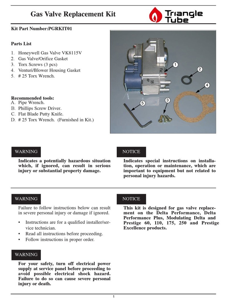
Parts List (Fig. 1)
1. Honeywell Gas Valve VR4615V
2. Gas Valve/Supply Pipe -ring
3. Gas Valve/ utlet Pipe -ring
4. (8) - M5 Torx Head Screws.
5. Torx Key (not shown)
Recommended Tools:
1. Adjustable Wrench.
2. Phillips Head Screwdriver
3. Small Flat Head Screwdriver
Failure to follow instructions below can result
in severe personal injury or damage if ignored.
• Instructions are for a qualified installer/ser-
vice technician.
• Read all instructions before proceeding.
• Follow instructions in proper order.
For your safety, turn off electrical power
supply at service panel before proceeding to
avoid possible electrical shock hazard.
Failure to do so can cause severe personal
injury or death.
This kit is designed for gas valve replace-
ment on the Prestige Solo 399 only equipped
with Trimax control.
WARNING
WARNING
NOTICE
Indicates a potentially hazardous situation
which, if ignored, can result in serious
injury or substantial property damage.
Indicates special instructions on installa-
tion, operation or maintenance, which are
important to equipment but not related to
personal injury hazards.
WARNING NOTICE
23
4
1
Fig. 1: Gas alve Kit
Gas alve Replacement Kit
Prestige Solo 399
2
PRESTIGE 399 BOILER INSTRUCTIONS:
1. Turn power to the unit “ FF”
2. Shut off the gas supply to the boiler at the main
manual shut off valve.
3. Remove the front jacket panel.
4. Remove the wires to the gas valve.
5. Disconnect the gas supply piping inside the
PRESTIGE at the union located just before the
gas valve.
6. Remove the 4 screws on the top of the gas
valve, securing the gas valve outlet extension
pipe to the valve, see Fig. 2.
7. Remove the gas valve from the PRESTIGE
unit.
8. Remove the 4 screws securing the gas valve sup-
ply piping adapter to the gas valve, see Fig. 2.
9. Remove the -rings in the gas valve supply pip-
ing adapter and gas valve outlet extension pipe.
10. Install the gas valve supply piping adapter and
-Ring gasket on the new gas valve using 4
screws supplies in kit. Ensure screws are tight.
11. Install the new gas valve and -Ring gasket to
the gas valve extension using the 4 screws sup-
plies in kit. Ensure screws are tight.
12. Reconnect the gas supply piping using two
wrenches. pen the manual gas shut off valve
to check and test all gas connections for leaks
before placing the PRESTIGE unit back into
operation. Repair leaks if found.
Do not check for gas leaks with an open
flame. Use a bubble test. Failure to check for
gas leaks can cause severe personal injury,
death or substantial property damage
13. Reconnect the wires to the gas valve, see Fig. 3.
14. Reposition the control module panel and reat-
tached the front jacket panel.
15. Turn the electrical power “ N” to the PRES-
TIGE to return the unit back into service.
WARNING
2
1
3
Fig. 2: Prestige 399 Gas alve Assembly
1. Gas Valve
2. Gas Valve Supply Piping Adapter
3. Gas Valve utlet Extension Pipe
3
COMBUSTION TEST
1. The installer MUST perform a complete com-
bustion check to ensure the following combus-
tion levels are met at high and low input firing
rates and the burner is operating at optimum
conditions.
Table 1: Combustion Settings
The combustion testing and adjustments
must be performed by a qualified installer,
service agency or the gas supplier. All com-
bustion measurements must be perform with
calibrated equipment to ensure proper read-
ings and accuracy.
Failure to perform a complete combustion
test at both high and low input rates may
result in incomplete combustion and the pro-
duction of carbon monoxide, which can
cause severe personal injury, death or sub-
stantial property damage.
2. Test for C 2 or 2 and for C during high fir-
ing rate. The combustion readings should be
within the range listed in Table 1. The CO
level should not exceed 100 ppm when com-
bustion is correct. Perform the following pro-
cedure to manually place the burner into high
fire.
Trimax Control Procedure
a. Press the round INSTALLER button. See
Fig. 3.
b. Enter the installer access code “054” by
using the LEFT and RIGHT buttons to
select a digit and the UP and DOWN but-
tons to change the digit. Press the OK but-
ton to enter the access code.
c. Press the RIGHT button to highlight the
Manual peration icon then press the
OK button.
d. Press the K button while the FAN icon is
highlighted to manually fire the burner and
power the CH circulator.
An adequate CH load must be present to dis-
sipate the heat generated during the combus-
tion test. If an adequate CH load is not avail-
able, an indirect water heater can be used to
dissipate the heat by creating a DHW call
which will enable the DHW circulator.
WARNING
WARNING
NOTICE
Gas alve Replacement Kit
Prestige Solo 399
Natural Gas Propane
O2 Min. 2.30% 3.70%
O2 Max. 5.30% 5.20%
CO2 Min. 8.80% 10.00%
CO2 Max. 10.50% 11.00%
CO Max. 100 ppm 100 ppm
Manual Operation
Released
O
O
O
CH
CH1
FAN
DHW
SYS
CH2
Installer
Button
Fig. 3: Trimax Navigation Buttons
Gas alve Replacement Kit
Prestige Solo 399
42011-67 Solo 399 Gas Valve Repl. Kit
1/15/20
e. Press the LEFT and RIGHT buttons to
adjust the firing rate from 0% to 100%.
Hold down the LEFT or RIGHT button to
rapidly increase or decrease the firing rate.
f. Press the OK button while the FAN icon is
highlighted to shutdown the burner.
g. Cycle power to the Prestige once combus-
tion testing is complete to return to normal
operation.
The combustion levels should be measured at
high firing rate. If the combustion levels are
not within the range given in Table 1 for the
firing rate, shut the boiler down and contact
Triangle Tube Engineering Department.
Failure to comply with this requirement
could result in severe personal injury, death
or substantial property damage.
If the combustion levels during high fire is outside
the recommended combustion settings adjust the
THR TTLE SCREW (see Fig. 4) as follows:
Counter-clockwise adjustment of the throttle
screw at high fire:
2decreases and C02increases
Clockwise adjustment of the throttle screw at
high fire:
2increases and C 2decreases
4. nce the combustion level is set at high fire,
manually place the boiler into low fire mode by
pressing the LEFT button to adjust firing rate
down.
5. If the combustion level during low fire is not
within +/-0.2% of the combustion level mea-
sured at high fire, adjust the metal offset screw
inside the brass fitting on the top right of the gas
valve (see Fig. 4) as follows.
Counter-clockwise adjustment of offset screw at
low fire:
2increases and 2decreases
Clockwise adjustment of offset screw at low fire:
2decreases and C 2increases
WARNING
Offset Pressure
Cover Screw
Throttle
Screw
Fig. 4: Combustion Adjustment - Prestige Burner

Other TriangleTube Control Unit manuals
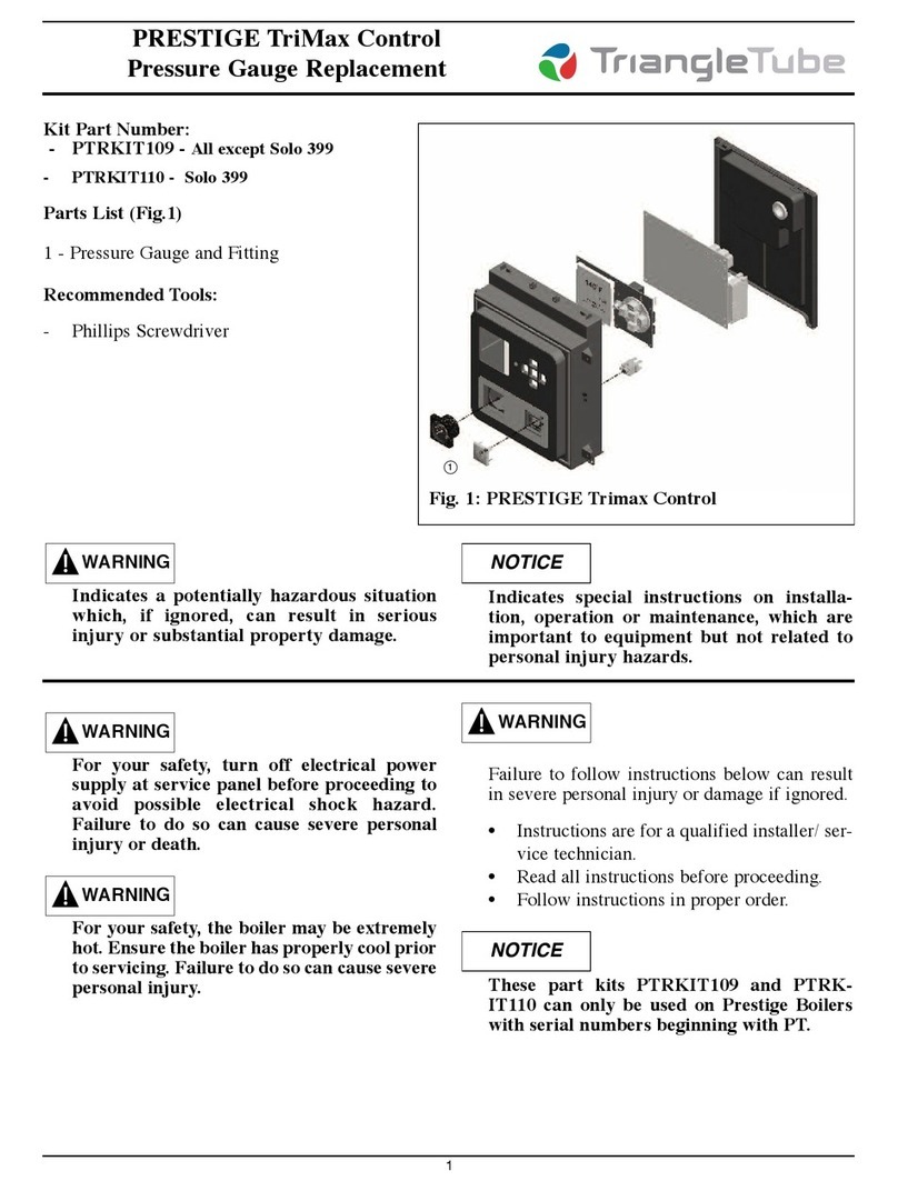
TriangleTube PRESTIGE TriMax PTRKIT109 User manual

TriangleTube

TriangleTube PRESTIGE TriMax PTRKIT109 User manual

TriangleTube PSRKIT23 User manual

TriangleTube

TriangleTube PSRKIT23 User manual

TriangleTube PSRKIT74 User manual

TriangleTube

TriangleTube PSRKIT74 User manual

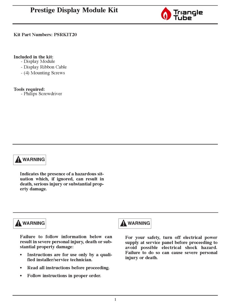
TriangleTube PSRKIT20 User manual

TriangleTube

TriangleTube PSRKIT20 User manual

TriangleTube Optima Series Installation instructions

TriangleTube

TriangleTube Optima Series Installation instructions

TriangleTube PGRKIT16 User manual

TriangleTube

TriangleTube PGRKIT16 User manual

TriangleTube CHALLENGER CC 85 User manual

TriangleTube

TriangleTube CHALLENGER CC 85 User manual

TriangleTube PGRKIT01 User manual

TriangleTube

TriangleTube PGRKIT01 User manual

TriangleTube PRESTIGE TriMax PTRKIT205 User manual

TriangleTube

TriangleTube PRESTIGE TriMax PTRKIT205 User manual

TriangleTube PGRKIT18 User manual

TriangleTube

TriangleTube PGRKIT18 User manual

TriangleTube INSRKIT06 User manual

TriangleTube

TriangleTube INSRKIT06 User manual

TriangleTube Prestige Trimax 175 User manual

TriangleTube

TriangleTube Prestige Trimax 175 User manual

TriangleTube Prestige Trimax 399 User manual

TriangleTube

TriangleTube Prestige Trimax 399 User manual

TriangleTube PTRKIT111 User manual

TriangleTube

TriangleTube PTRKIT111 User manual
Popular Control Unit manuals by other brands

ABB CP-A RU Operating and installation instructions

ABB

ABB CP-A RU Operating and installation instructions

gefran GFW adv Series INSTRUCTION MANUAL FOR CONFIGURATION AND INSTALLATION

gefran

gefran GFW adv Series INSTRUCTION MANUAL FOR CONFIGURATION AND INSTALLATION

SMC Networks ASN2 Series Operation manual

SMC Networks

SMC Networks ASN2 Series Operation manual

FNW HP Series Installation, operation and maintenance instructions

FNW

FNW HP Series Installation, operation and maintenance instructions

Danfoss PM3 Installation guides

Danfoss

Danfoss PM3 Installation guides

Siamp STORM 33A Assembly instructions

Siamp

Siamp STORM 33A Assembly instructions

Micropelt MVA004 EnOcean quick start

Micropelt

Micropelt MVA004 EnOcean quick start

FireClass FC410DIM quick start guide

FireClass

FireClass FC410DIM quick start guide

Freescale Semiconductor MCF5441X user manual

Freescale Semiconductor

Freescale Semiconductor MCF5441X user manual

Siemens RMH760B installation instructions

Siemens

Siemens RMH760B installation instructions

Hi-Link HLK-B36 user manual

Hi-Link

Hi-Link HLK-B36 user manual

Pentair PENTEK INTELLIDRIVE PID2000-1123 owner's manual

Pentair

Pentair PENTEK INTELLIDRIVE PID2000-1123 owner's manual

Watts DRV Series Technical data sheet

Watts

Watts DRV Series Technical data sheet

Siemens Cm-lon 6BK1700-0BA10-0AA00 manual

Siemens

Siemens Cm-lon 6BK1700-0BA10-0AA00 manual

National Instruments 9503 User manual and specifications

National Instruments

National Instruments 9503 User manual and specifications

Woodward MicroNet 8237-1252 product manual

Woodward

Woodward MicroNet 8237-1252 product manual

Allmatic CT INVERTER AM Manual for installation

Allmatic

Allmatic CT INVERTER AM Manual for installation

IDEC MicroSmart pentra FC5A-C10R2 user manual

IDEC

IDEC MicroSmart pentra FC5A-C10R2 user manual

manuals.online logo
manuals.online logoBrands
  • About & Mission
  • Contact us
  • Privacy Policy
  • Terms and Conditions

Copyright 2025 Manuals.Online. All Rights Reserved.