manuals.online logo
Brands
  1. Home
  2. •
  3. Brands
  4. •
  5. TriangleTube
  6. •
  7. Control Unit
  8. •
  9. TriangleTube PRESTIGE TriMax PTRKIT109 User manual

TriangleTube PRESTIGE TriMax PTRKIT109 User manual

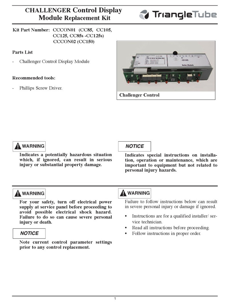
PRESTIGE TriM x Control
Pressure G uge Repl cement
1
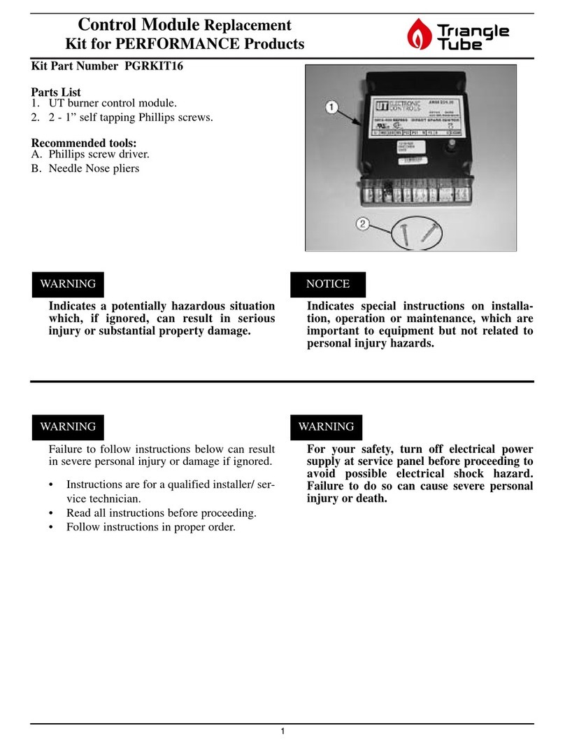
Kit P rt Number:
- PTRKIT109 - All except Solo 399
- PTRKIT110 - Solo 399
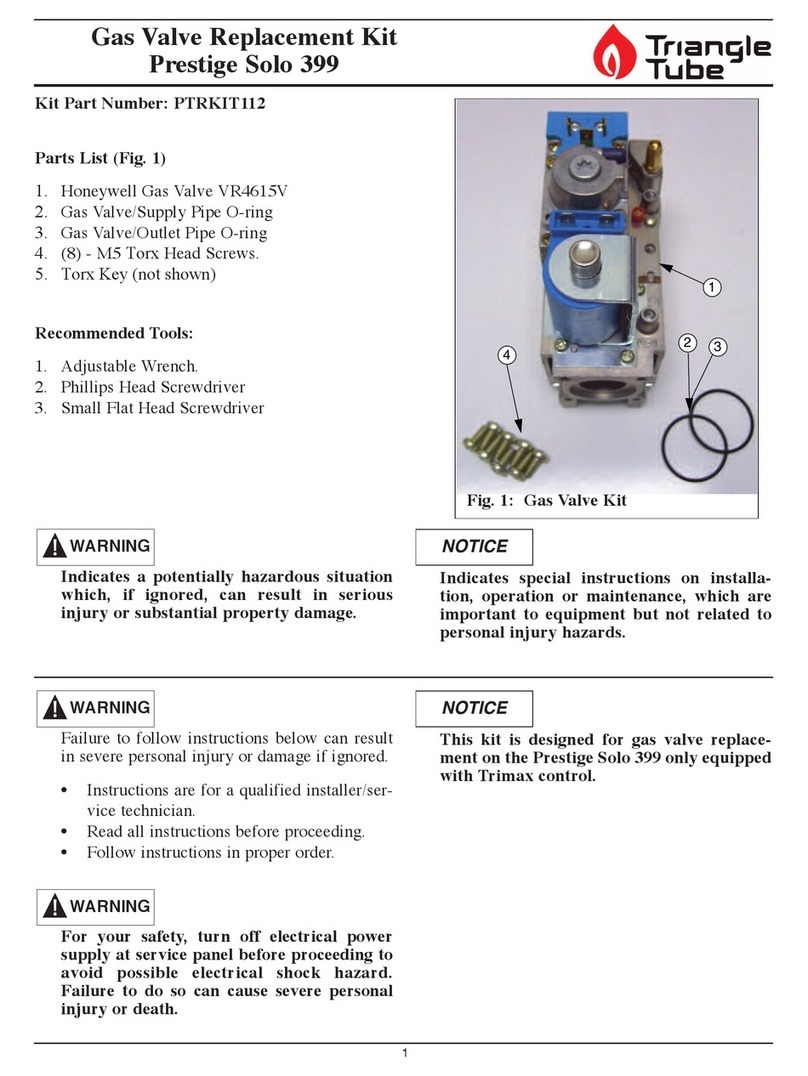
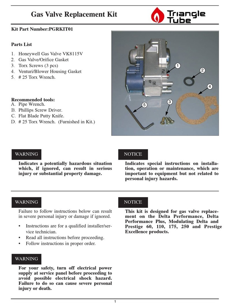
P rts List (Fig.1)
1 - Pressure Gauge and Fitting
Recommended Tools:
- Phillips Screwdriver
Indic tes potenti lly h z rdous situ tion
which, if ignored, c n result in serious
injury or subst nti l property d m ge.
For your s fety, turn off electric l power
supply t service p nel before proceeding to
void possible electric l shock h z rd.
F ilure to do so c n c use severe person l
injury or de th.
For your s fety, the boiler m y be extremely
hot. Ensure the boiler h s properly cool prior
to servicing. F ilure to do so c n c use severe
person l injury.
Indic tes speci l instructions on inst ll -
tion, oper tion or m inten nce, which re
import nt to equipment but not rel ted to
person l injury h z rds.
Failure to follow instructions below can result
in severe personal injury or damage if ignored.
• Instructions are for a qualified installer/ ser-
vice technician.
• Read all instructions before proceeding.
• Follow instructions in proper order.
These p rt kits PTRKIT109 nd PTRK-
IT110 c n only be used on Prestige Boilers
with seri l numbers beginning with PT.
WARNING
WARNING
NOTICE
WARNING
NOTICE
WARNING
1
Fig. 1: PRESTIGE Trim x Control
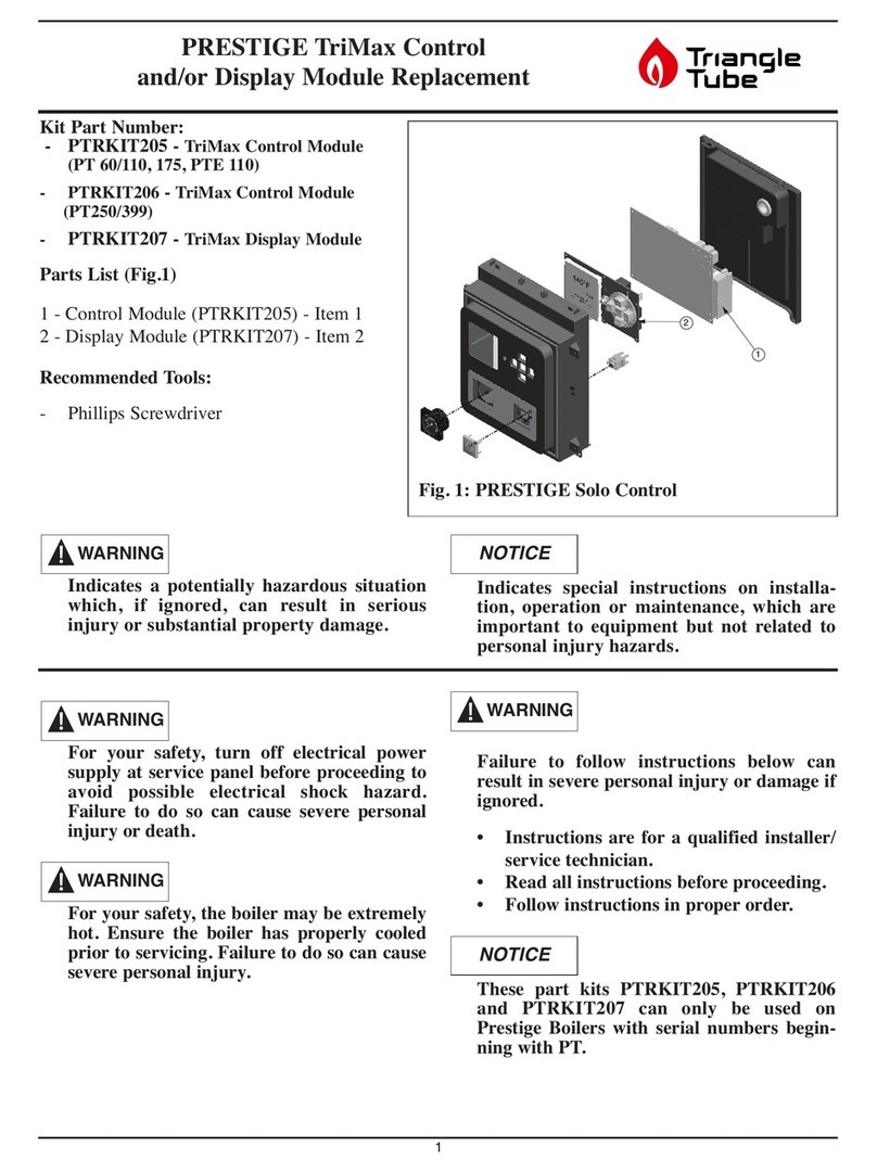
PRESTIGE TriM x Control
Pressure G uge Repl cement
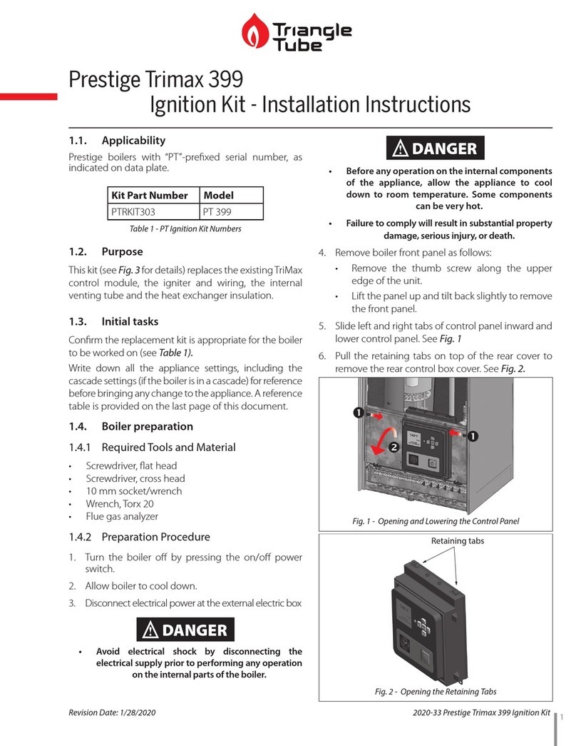
Remov l of Pressure G uge nd Fitting.
1. urn the electrical power “OFF”.
2. Remove the front jacket panel by removing the
thumb screw along the upper edge of the unit.
Lift it up and tilt back slightly to remove the
front panel.
3. Slide left and right tabs of control panel inward
and lower control panel. See Fig. 2.
4. Disconnect the ignition cable by grasping the
wire and pulling firmly upwards from the back
of the control box. Use care not to damage the
ignition cable or ignition terminal.
5. Pull the retaining tabs on top of the rear cover to
remove the rear control box cover. See Fig. 3.
Note: In case one cannot access the pressure
gauge on the back of the control panel
directly, go to step 8.
6. Unscrew the union nut connecting the pressure
gauge fitting to the return piping.
7. Push the tabs located on the side of the pressure
gauge, and carefully pull out the gauge and cap-
illary piping.
Remov l of Trim x Control Module
8. Label and remove all (8) Molex wiring connec-
tors from the Control Module. Support rimax
Control Module with one hand while removing
individual Molex connectors. Use tabs on
Molex plugs for quick release. See Fig. 4
9. Remove the 2 screws securing the Control
Module into the enclosure and remove the
Control Module. Do not discard the rimax
Control Module. See Fig. 5.
2
Retaining
Tab
Retaining
Tab
Panel
will pivot
downward
Fig. 2: Opening & Lowering Control P nel
Retaining Tabs
Fig. 3: Control Box Assembly
1
2
6
5
43
7
8
Fig. 4: Control Module Molex Connections
PRESTIGE TriM x Control
Pressure G uge Repl cement
3
Inst ll tion of the Prestige Trim x Pressure
G uge
10. Guide the pressure fitting through the display
panel opening to the return piping. Be careful
not to kink the capillary piping.
11. Mount the new pressure gauge into its location
on the enclosure (push in the tabs). Make sure
the pressure display is oriented properly.
12. Insert the pressure fitting into the return piping.
13. ighten the union nut of the new pressure fitting
to the return piping.
Note: If the rimax Control Module was removed,
follow step below. Else proceed to step 17.
Inst ll tion of Trim x Control Module
14. Mount the rimax Control Module into the
enclosure by positioning the board onto the pro-
truding pins.
15. Use existing mounting screws to secure the
Control Module.
16. Reconnect the 8 Molex connectors to proper
positions as shown in Fig. 4. Each connector is
designed to fit only in its respective mating
connector.
17. Place the rear cover in place and lock in the top
retaining tabs.
18. Push ignition cable in place onto the Control
Module ignition connector.
19. ilt control panel assembly upward and lock
sliding tabs in place.
20. Remount the front jacket panel to the boiler.
21. urn power to the unit “ON” and return the
boiler to service.
Mounting
screw
location
Mounting
screw
location
Fig. 5. Control Module Mounting
1
2
3
4
5
6
Fig. 6. Control Module Mounting
Date: 2/22/12 2012-25 Prestige_ riMax Pressure Gauge Repl

This manual suits for next models

1

Other TriangleTube Control Unit manuals
TriangleTube PGRKIT16 User manual

TriangleTube

TriangleTube PGRKIT16 User manual

TriangleTube INSRKIT06 User manual

TriangleTube

TriangleTube INSRKIT06 User manual

TriangleTube PSRKIT23 User manual

TriangleTube

TriangleTube PSRKIT23 User manual

TriangleTube PTRKIT112 User manual

TriangleTube

TriangleTube PTRKIT112 User manual

TriangleTube Optima Series Installation instructions

TriangleTube

TriangleTube Optima Series Installation instructions

TriangleTube Prestige Trimax 175 User manual

TriangleTube

TriangleTube Prestige Trimax 175 User manual

TriangleTube PSRKIT74 User manual

TriangleTube

TriangleTube PSRKIT74 User manual
TriangleTube PGRKIT01 User manual

TriangleTube

TriangleTube PGRKIT01 User manual

TriangleTube CHALLENGER CC 85 User manual

TriangleTube

TriangleTube CHALLENGER CC 85 User manual

TriangleTube Prestige Trimax 399 User manual

TriangleTube

TriangleTube Prestige Trimax 399 User manual

TriangleTube PSRKIT20 User manual

TriangleTube

TriangleTube PSRKIT20 User manual

TriangleTube PRESTIGE TriMax PTRKIT205 User manual

TriangleTube

TriangleTube PRESTIGE TriMax PTRKIT205 User manual

TriangleTube PGRKIT18 User manual

TriangleTube

TriangleTube PGRKIT18 User manual

TriangleTube PTRKIT111 User manual

TriangleTube

TriangleTube PTRKIT111 User manual
Popular Control Unit manuals by other brands

Aventics CONTROLAIR H-4 Service information

Aventics

Aventics CONTROLAIR H-4 Service information

Gemu 410 Installation, Operating and Maintenance Instructions for the Installer and the User

Gemu

Gemu 410 Installation, Operating and Maintenance Instructions for the Installer and the User

Atmel STK504 user guide

Atmel

Atmel STK504 user guide

Mini-Circuits RC8DAT-8G-95 user guide

Mini-Circuits

Mini-Circuits RC8DAT-8G-95 user guide

In2 Networks Energy ICM quick start guide

In2 Networks

In2 Networks Energy ICM quick start guide

VIPA System 300S IM 353-1DP01 manual

VIPA

VIPA System 300S IM 353-1DP01 manual

BROWER TIMING SYSTEM MC Series instructions

BROWER TIMING SYSTEM

BROWER TIMING SYSTEM MC Series instructions

Pentair SIATA V132 SFE-EV VIRIDION user guide

Pentair

Pentair SIATA V132 SFE-EV VIRIDION user guide

Lawler 911 E/F Series quick start guide

Lawler

Lawler 911 E/F Series quick start guide

Extron electronics IRCM-DVplus user manual

Extron electronics

Extron electronics IRCM-DVplus user manual

HP E2261A user manual

HP

HP E2261A user manual

AVE AF927PLUS Installation and user manual

AVE

AVE AF927PLUS Installation and user manual

Burkert 6211 Operating instructions manual

Burkert

Burkert 6211 Operating instructions manual

Taco Comfort Solutions ZVC406 instruction sheet

Taco Comfort Solutions

Taco Comfort Solutions ZVC406 instruction sheet

Johnson Controls Penn A19K Series Installation Sheets Manual

Johnson Controls

Johnson Controls Penn A19K Series Installation Sheets Manual

Go BlueConnect manual

Go

Go BlueConnect manual

Audio Technica AT8351 Operation and maintenance instruction

Audio Technica

Audio Technica AT8351 Operation and maintenance instruction

Ericsson DM-20 Interface manual

Ericsson

Ericsson DM-20 Interface manual

manuals.online logo
manuals.online logoBrands
  • About & Mission
  • Contact us
  • Privacy Policy
  • Terms and Conditions

Copyright 2025 Manuals.Online. All Rights Reserved.