manuals.online logo
Brands
  1. Home
  2. •
  3. Brands
  4. •
  5. TriangleTube
  6. •
  7. Control Unit
  8. •
  9. TriangleTube CHALLENGER CC 85 User manual

TriangleTube CHALLENGER CC 85 User manual

Kit Part Number: CCCON01 (CC85, CC105,
CC125, CC85s -CC125s)
CCCON02 (CC150)
Parts List
- Ch llenger Control Displ y Module
Recommended tools:
- Phillips Screw Driver.
CHALLENGER Control Display
Module Replacement Kit
1
Indicates a potentially hazardous situation
which, if ignored, can result in serious
injury or substantial property damage.
For your safety, turn off electrical power
supply at service panel before proceeding to
avoid possible electrical shock hazard.
Failure to do so can cause severe personal
injury or death.
Note current control parameter settings
prior to any control replacement.
Indicates special instructions on installa-
tion, operation or maintenance, which are
important to equipment but not related to
personal injury hazards.
F ilure to follow instructions below c n result
in severe person l injury or d m ge if ignored.
• Instructions re for qu lified inst ller/ ser-
vice technici n.
• Re d ll instructions before proceeding.
• Follow instructions in proper order.
WARNING WARNING
NOTICE
NOTICE
WARNING
Challenger Control
Module replacement Instructions
1. Turn the power to the unit OFF by disconnect-
ing the m in power source.
ELECTRICAL SHOCK HAZARD. The
ON/OFF switch of the boiler does not discon-
nect electrical power to the module.
Disconnect electrical power to the boiler
using the main service switch.
2. Remove the front j cket p nel by loosening the
ret ining screws on e ch side of the displ y.
3. Dismount the front j cket p nel by pulling the
bottom of the front p nel out nd the entire front
j cket p nel down.
4. Pull the Control Displ y Module tr y out from
the bottom j cket p nel nd swing the tr y
downw rd. The guide pins on the tr y should
diseng ge the bottom p nel (Fig.2).
Before proceeding to the following steps
mark and label all connections and location
of the connections prior to disconnecting any
wire connections.
5. Disconnect ll molex plugs from the module.
The two white molex plugs nd one grey molex
plug h ve locking levers th t need to be disen-
g ged prior to disconnection.
6. Disconnect the (4) ground wires from the mod-
ule. Use c re not to d m ge the wire termin ls.
7. To remove the module from the tr y, diseng ge
the re r ret ining t bs of the module from the
tr y sides by c refully pulling the tr y sides
slightly outw rd.
8. Once the ret ining t bs re diseng ged slide the
module b ck nd upw rd w y from the f ce
pl te of the tr y.
Do not discard the module if a warranty
claim is being submitted. Contact Triangle
Tube Customer Service for information
regarding the warranty period of the module
and if a RGA number is needed to return the
damaged module. If the control was shipped
with a RET RN SHIPPING LABEL, send
module directly back to Triangle Tube.
NOTICE
WARNING
NOTICE
CHALLENGER Control Display
Module Replacement Kit
2
Fig. 2: Removal of control module
Fig. 1: Loosening of retained screws
9. Mount the new module into the tr y by sliding
the front of the module with displ y g inst the
tr y’s f cepl te. Align the module or nge but-
tons to se t within the cutouts of the tr y.
10. Sn p the b ck of the module into pl ce by
slightly pulling the sides of the tr y outw rd
using c re not to d m ge the tr y. The ret ining
t bs of the module should lock into the tr y.
To ensure proper installation of the module
into the tray, press several of the buttons on
the display panel. Each button should have a
clear “click” sound and feel. If not, reinstall
the module into the tray ensuring the module
retaining tabs are locked into the tray.
11. Reconnect ll molex plugs to the module. The
two white molex plugs nd one grey molex plug
h ve locking levers th t need to be eng ged to
ensure proper connection.
12. Reconnect the (4) ground wires from the module.
13. Reeng ge the guide pins of the module tr y into
the bottom j cket p nel. Rot te the tr y up into
position.
Ensure control wiring does not hinder the
insertion of the try into the bottom jacket
panel.
14. Mount the front j cket p nel by eng ging the top
of the p nel into the top j cket p nel (Fig. 3).
15. Swing the bottom of the front j cket g inst the
side p nel nd secure in pl ce by tightening the
ret ining screws (Fig. 1).
16. Turn power to the boiler ON nd return the boil-
er to service.
17. Reference the m nu l section Setting Appli nce
P r meters for steps needed to revise the con-
trols p r meter settings.
NOTICE
NOTICE
CHALLENGER Control Display
Module Replacement Kit
3
D te: 2/22/12 2012-20 Module Control Displ y Repl. Kit Ch llenger
Fig. 3: Installation of front panel

Other manuals for CHALLENGER CC 85

3

This manual suits for next models

6

Other TriangleTube Control Unit manuals
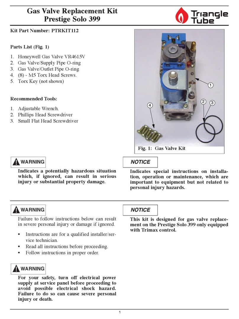
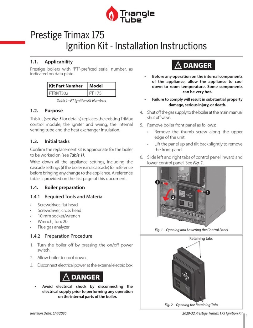
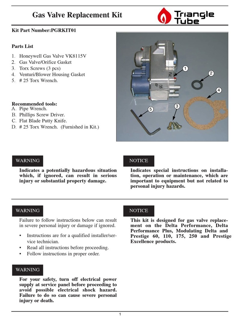
TriangleTube PGRKIT18 User manual

TriangleTube

TriangleTube PGRKIT18 User manual

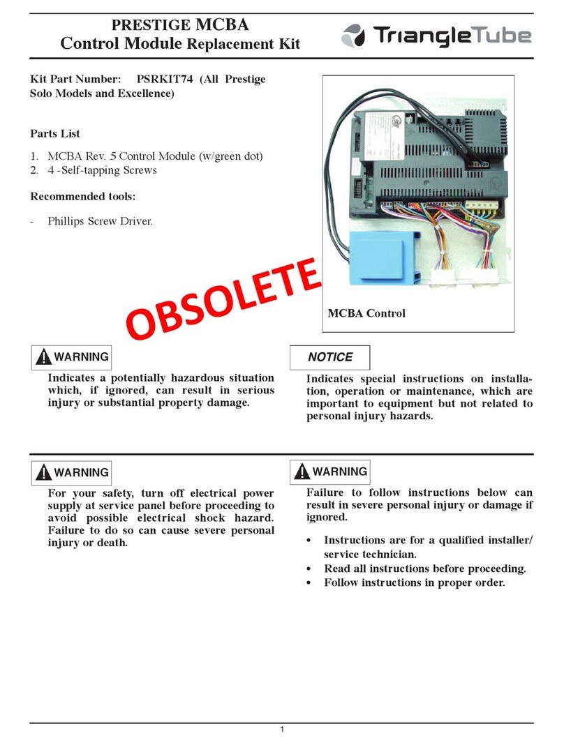
TriangleTube PSRKIT74 User manual

TriangleTube

TriangleTube PSRKIT74 User manual

TriangleTube Prestige Trimax 175 User manual

TriangleTube

TriangleTube Prestige Trimax 175 User manual

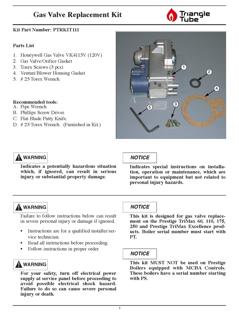
TriangleTube PTRKIT111 User manual

TriangleTube

TriangleTube PTRKIT111 User manual

TriangleTube INSRKIT06 User manual

TriangleTube

TriangleTube INSRKIT06 User manual

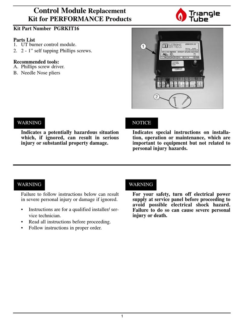
TriangleTube PGRKIT16 User manual

TriangleTube

TriangleTube PGRKIT16 User manual

TriangleTube PGRKIT01 User manual

TriangleTube

TriangleTube PGRKIT01 User manual

TriangleTube PSRKIT20 User manual

TriangleTube

TriangleTube PSRKIT20 User manual
TriangleTube PRESTIGE TriMax PTRKIT205 User manual
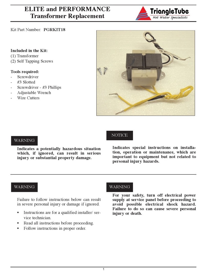
TriangleTube

TriangleTube PRESTIGE TriMax PTRKIT205 User manual

TriangleTube PRESTIGE TriMax PTRKIT109 User manual

TriangleTube

TriangleTube PRESTIGE TriMax PTRKIT109 User manual

TriangleTube PTRKIT112 User manual

TriangleTube

TriangleTube PTRKIT112 User manual
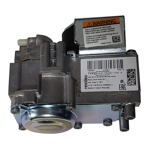
TriangleTube Prestige Trimax 399 User manual

TriangleTube

TriangleTube Prestige Trimax 399 User manual

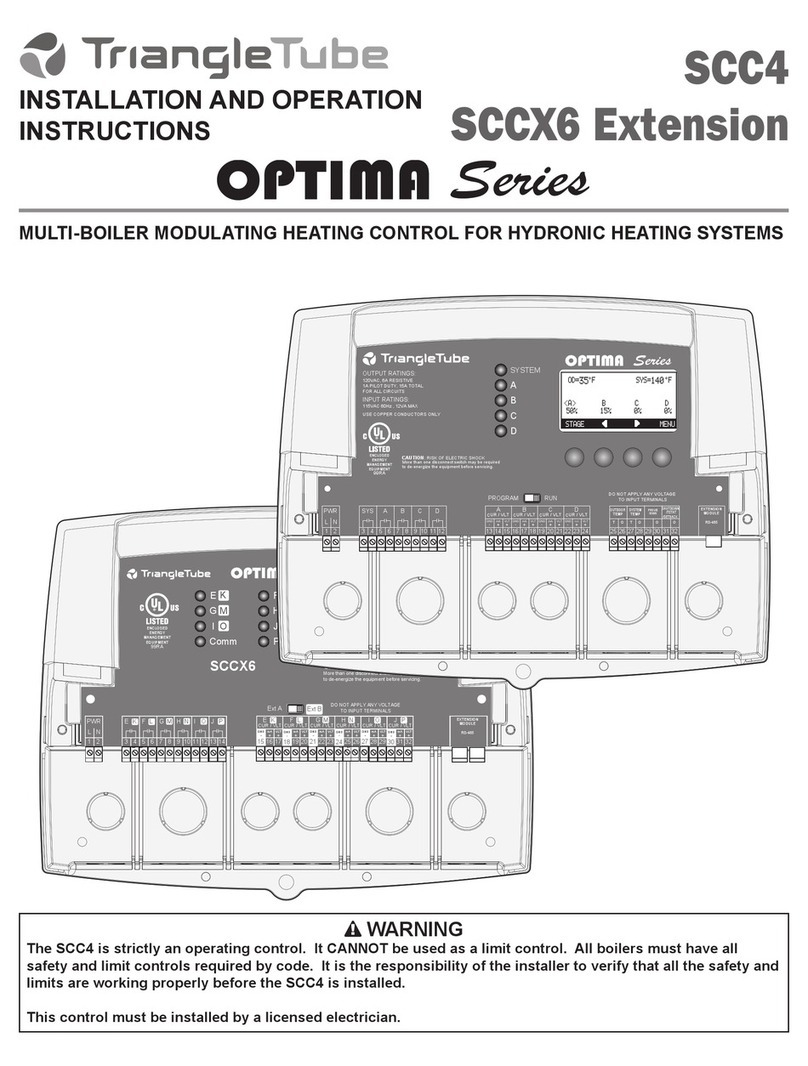
TriangleTube Optima Series Installation instructions

TriangleTube

TriangleTube Optima Series Installation instructions

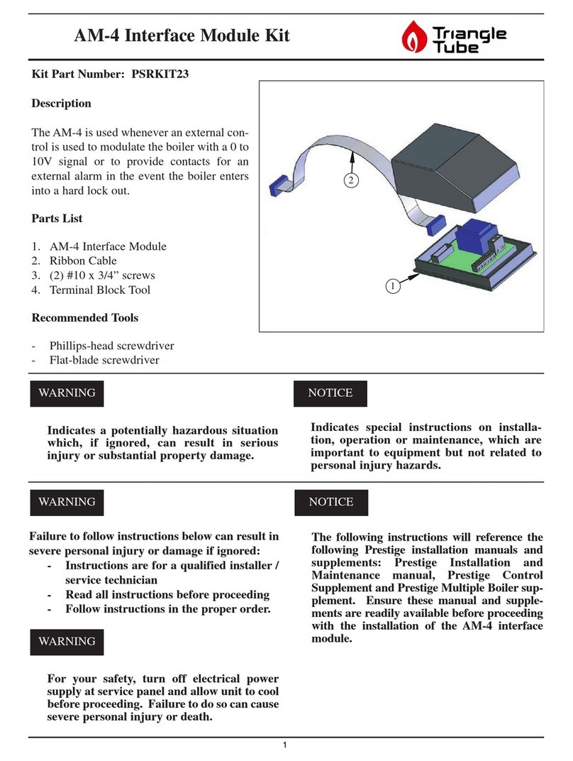
TriangleTube PSRKIT23 User manual

TriangleTube

TriangleTube PSRKIT23 User manual

Popular Control Unit manuals by other brands

Rauch QUANTRON-A instruction manual

Rauch

Rauch QUANTRON-A instruction manual

Digi Connect Wi-ME 9210 quick start guide

Digi

Digi Connect Wi-ME 9210 quick start guide

Vortice NA 100 Instruction booklet

Vortice

Vortice NA 100 Instruction booklet

PulseWorx AM1 Installation guide and owner's manual

PulseWorx

PulseWorx AM1 Installation guide and owner's manual

MSA M1 operating manual

MSA

MSA M1 operating manual

SCHUNK LDH Series Assembly and operating manual

SCHUNK

SCHUNK LDH Series Assembly and operating manual

dymax 485 user guide

dymax

dymax 485 user guide

claber Hydro 4 Use and installation  manual

claber

claber Hydro 4 Use and installation manual

PT Coupling Maxi-Dry Disassembly instructions

PT Coupling

PT Coupling Maxi-Dry Disassembly instructions

Siemens SIMATIC ET 200SP manual

Siemens

Siemens SIMATIC ET 200SP manual

ZIEHL-ABEGG U-EK230E operating instructions

ZIEHL-ABEGG

ZIEHL-ABEGG U-EK230E operating instructions

Infineon Cypress EZ-BLE CYBLE-022001-00 manual

Infineon

Infineon Cypress EZ-BLE CYBLE-022001-00 manual

Innophase Talaria TWO Hardware user's guide

Innophase

Innophase Talaria TWO Hardware user's guide

Rockwell Automation 1606-XLSBATASSY3 instruction manual

Rockwell Automation

Rockwell Automation 1606-XLSBATASSY3 instruction manual

Asco FLOWTRONIC D 60701073 installation manual

Asco

Asco FLOWTRONIC D 60701073 installation manual

QEI 6PTM2 Series user guide

QEI

QEI 6PTM2 Series user guide

Pickering 41-761 user manual

Pickering

Pickering 41-761 user manual

Burkert 0124 operating instructions

Burkert

Burkert 0124 operating instructions

manuals.online logo
manuals.online logoBrands
  • About & Mission
  • Contact us
  • Privacy Policy
  • Terms and Conditions

Copyright 2025 Manuals.Online. All Rights Reserved.