Trix 1800 Series User manual

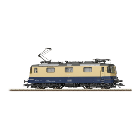
Modell der Elektrolokomotive Serie 1800
22575
F
D GB USA NL

2

3
Inhaltsverzeichnis: Seite
Informationen zum Vorbild 4
Sicherheitshinweise 6
Wichtige Hinweise 6
Multiprotokollbetrieb 6
Schaltbare Funktionen 9
Parameter/Register 10
Wartung und Instandhaltung 26
Ersatzteile 34
Table of Contents: Page
Information about the prototype 4
Safety Notes 11
Important Notes 11
Multi-Protocol Operation 11
Controllable Functions 14
Parameter/Register 15
Service and maintenance 26
Spare Parts 34
Sommaire : Page
Informations concernant la locomotive réelle 5
Remarques importantes sur la sécurité 16
Information importante 16
Mode multiprotocole 16
Fonctions commutables 19
Paramètre/Registre 20
Entretien et maintien 26
Pièces de rechange 34
Inhoudsopgave: Pagina
Informatie van het voorbeeld 5
Veiligheidsvoorschriften 21
Belangrijke aanwijzing 21
Multiprotocolbedrijf 21
Schakelbare functies 24
Parameter/Register 25
Onderhoud en handhaving 26
Onderdelen 34

4
Informationen zum Vorbild
Nach verschiedenen Versuchen mit den von den BB 9400 ab-
geleiteten Prototyp-Lokomotiven BB 30001 und 30002 (früher
als 26001 und 26002 immatrikuliert), beschloss die SNCF eine
Lokomotive zu bauen, die unter 4 verschiedenen Spannungen
fahren kann: die CC 40100. Ihr innovatives Design machte aus
diesen Maschinen die ersten mit einer sogenannten „gebro-
chenen Nase“ (nez cassé) an den Triebköpfen. Das Erschei-
nungsbild der CC 40100 ist eng verbunden mit den Edelstahl-
wagen der TEE Paris-Brüssel-Amsterdam oder Mistral 69, mit
denen sie bis zur ihrer Ausmusterung in Umlauf waren. Einige
Jahre nach der Lieferung der CC 40100 beschloss Belgien
identische, aber für 3 Spannungen ausgelegte Lokomotiven
einzustellen, die zur berühmten BR 18 gehören und in den
Farben Stahl, gelb und blau gehalten sind.
Während ihrer kurzen, kaum dreißigjährigen Laufbahn hat
die gesamte Baureihe der CC 40100 einen sehr beachtlichen
Einsatz zwischen Brüssel und Paris geleistet. Die ständig
steigenden Unterhaltskosten und ihre nachlassende Zuver-
lässigkeit ließen damals eine mehr als ungewisse Zukunft
voraussehen. Erst im Sommerfahrplan vom 31. Mai 1996
wurden die letzten noch im Einsatz stehenden Maschinen,
die 40109 und 40110, aus dem Bestand der SNCF gestrichen,
als der TGV Thalys PBA (=Paris-Brüssel-Amsterdam) seinen
Dienst aufnahm. Bis zur ihrer Ausmusterung am 12. Juli
1999 verkehrten die Maschinen der belgischen BR 18 auf
anderen Strecken.
Das Verschwinden der CC 40100 beendet die Blütezeit
der TEE, die in der zweiten Hälfte des 20. Jahrhunderts in
ganz Europa verkehrten. Die CC 40101, 40109 et 40110 sind
erhalten geblieben.
Information about the prototype
After different attempts with the BB 30001 and 30002
(designated earlier as road nos. 26001 and 26002) prototype
locomotives developed from the BB 9400, the SNCF decided
to build a locomotive that could be run under 4 different
voltages: the CC 40100. Its innovative design at the ends
of these locomotives made them the first of the so-called
„Broken Noses“ („Nez Cassé“ in French). The typical look
of the CC 40100 is closely linked with the stainless steel cars
for the Paris-Brussels-Amsterdam TEE or the Mistral 69, and
it ran with them until it was retired. Several years after the
delivery of the CC 40100, Belgium decided to use identical
locomotives (but designed for 3 voltage systems) that were
part of the famous class 18 and that were maintained in
stainless steel along with the colors yellow and blue.
All of the class CC 40100 locomotives performed notably
between Brussels and Paris during their short career of
barely 30 years. The constantly rising maintenance costs
and their decreasing reliability left them prey to a more than
uncertain future. The last units still in service, road nos.
40109 and 40110, were not removed from the SNCF roster
until the summer schedule of May 31, 1996, when the TGV
Thalys PBA (= Paris-Brussels-Amsterdam) entered service.
The Belgian class 18 units were in service on other routes
up to their retirement on July 12, 1999.
The disappearance of the CC 40100 ended the heyday of
the TEE trains that run all over Europe in the second half of
the 20th century. Road nos. CC 40101, 40109, and 40110 have
remained preserved.

5
Informations concernant le modèle réel
Après différents essais menés sur les locomotives proto-
types BB 30001 et 30002 (autrefois appelées 26001 et 26002)
dérivées des BB 9400, la SNCF décide de construire une mo-
trice capable de circuler sous quatre tensions différentes,
la CC 40100. Avec un design innovant, ces engins sont les
premiers dotés d‘une face frontale dite „Nez cassé“. Ces
motrices sont indissociables des rames formées par les voi-
tures Trans Europ Express Inox Paris-Bruxelles-Amsterdam
ou Mistral 69 avec lesquelles elles ont circulé jusqu‘à leur
radiation. La Belgique décide quelques années après la
livraison des CC 40100 de mettre en service des locomotives
tritension identiques, appartenant à la fameuse série 18 et
possédant une livrée inox, jaune et bleue.
Durant leur courte carrière à peine trentenaire, la totalité
de la série des CC 40100 a effectué un service de renom en
tête des prestigieux TEE entre Paris et Bruxelles. Les coûts
d‘entretien devenant sans cesses plus onéreux ainsi que
leur fiabilité mauvaise laissent entrevoir un devenir alors
plus qu‘incertain. Ce n‘est que lors du service d‘été du
31 mai 1996 que les dernières locomotives encore en ser-
vice, les CC 40109 et 40110 se voient rayées des effectifs de
la SNCF, lors de l‘arrivée des TGV PBA Thalys. Les machines
de la série 18 belge ont circulé quant à elles sur d‘autres
liaisons jusqu‘à leur radiation le 12 juillet 1999.
La disparition des CC 40100 a constitué la fin de l‘époque
prestigieuse des TEE sillonnant l‘Europe durant la seconde
moité du 20ème siècle. Les CC 40101, 40109 et 40110 ont été
préservées.
Informatie over het voorbeeld
Na verschillende proeven met de van de BB 9400 afgeleide
prototype locomotieven BB 30001 en 30002 (vroeger als
26001 en 26002 ingeschreven), besloot de SNCF een locomo-
tief te bouwen, die op vier verschillende spanningssystemen
kon rijden: de CC40100. Met dit innovatieve design was
het de eerste machine met een zgn. “Gebroken neus” (nez
cassé) aan het front van de loc. De verschijning van de
CC 40100 deed sterk denken aan de roestvrijstalen rijtuigen
van de TEE Parijs-Brussel-Amsterdam of de Mistral 69 waar-
door ze getrokken werden tot de buitendienststelling. Enkele
jaren na de levering van de CC 40100 besloot België identie-
ke locomotieven, echter geschikt voor drie spanningssyste-
men, in te zetten die tot de beroemde serie 18 behoren en in
de kleuren staal, geel en blauw zijn geschilderd.
Gedurende hun korte loopbaan van amper dertig jaar heeft
de hele serie CC 40100 een zeer opmerkelijk resultaat gebo-
ekt in de treindienst tussen Brussel en Parijs. Voortdurend
stijgende onderhoudskosten en nalatende betrouwbaarheid
lieten destijds zeker geen rooskleurige toekomst zien. Pas
in de zomerdienst vanaf 31 mei 1996 werden de laatste ma-
chines, de 40109 en 40110 uit het locomotievenbestand van
de SNCF gehaald toen de TGV Thalys PBA (Parijs-Brussel-
Amsterdam) in dienst genomen werd. Tot hun buitendienst-
stelling op 12 juli 1999 reden de machines van de Belgische
serie 18 op andere trajecten.
Met het verdwijnen van de CC 40100 kwam er een eind
aan de bloeitijd van de TEE die in de tweede helft van de
twintigste eeuw door heel Europa reed. De CC 40101, 40109
en de 40110 zijn bewaard gebleven.

6
Sicherheitshinweise
• DieLokdarfnurmiteinemdafürbestimmtenBetriebssys-
tem eingesetzt werden.
• Analogmax.15Volt=,digitalmax.22Volt~.
• DieLokdarfnurauseinerLeistungsquelleversorgt
werden.
• BeachtenSieunbedingtdieSicherheitshinweiseinder
Bedienungsanleitung zu Ihrem Betriebssystem.
• FürdenkonventionellenBetriebderLokmussdasAn-
schlussgleis entstört werden. Dazu ist das Entstörset
611 655 zu verwenden. Für Digitalbetrieb ist das Entstör-
set nicht geeignet.
• ACHTUNG! Funktionsbedingte scharfe Kanten und Spitzen.
• SetzenSiedasModellkeinerdirektenSonneneinstrah-
lung, starken Temperaturschwankungen oder hoher
Luftfeuchtigkeit aus.
• VerbauteLED`sentsprechenderLaserklasse1nach
Norm EN 60825-1.
Wichtige Hinweise
• DieBedienungsanleitungunddieVerpackungsind
Bestandteile des Produktes und müssen deshalb aufbe-
wahrt sowie bei Weitergabe des Produktes mitgegeben
werden.
• FürReparaturenoderErsatzteilewendenSiesichbittean
Ihren Trix-Fachhändler.
• GewährleistungundGarantiegemäßderbeiliegenden
Garantieurkunde.
• Entsorgung:www.maerklin.com/en/imprint.html
• DervolleFunktionsumfangistnurunterTrixSystems,
DCC und unter mfx verfügbar.
• Eingebaute,fahrtrichtungsabhängigeStirnbeleuchtung.
Im Digitalbetrieb schaltbar.
• BefahrbarerMindestradius360mm.
Multiprotokollbetrieb
Analogbetrieb
Der Decoder kann auch auf analogen Anlagen oder Gleis-
abschnitten betrieben werden. Der Decoder erkennt die
analoge Gleichspannung (DC) automatisch und passt sich
der analogen Gleisspannung an. Es sind alle Funktionen,
die unter mfx oder DCC für den Analogbetrieb eingestellt
wurden aktiv (siehe Digitalbetrieb).
Digitalbetrieb
Der Decoder ist ein Multiprotokolldecoder. Der Decoder
kann unter folgenden Digital-Protokollen eingesetzt werden:
mfx oder DCC.
Das Digital-Protokoll mit den meisten Möglichkeiten ist das
höchstwertige Digital-Protokoll. Die Reihenfolge der Digital-
Protokolle ist in der Wertung fallend:
Priorität 1: mfx
Priorität 2: DCC
Priorität 3: DC
Hinweis: Wenn zwei oder mehr digital-Protokolle am
Gleis erkannt werden, wählt der Decoder automatisch das
höchstwertige Protokoll. Wird z.B. mfx und DCC erkannt,
wählt der Decoder mfx.

7
Hinweis: Beachten Sie, dass nicht alle Funktionen in allen
Digital-Protokollen möglich sind. Unter mfx und DCC können
einige Einstellungen von Funktionen, welche im Analog-
Betrieb wirksam sein sollen, vorgenommen werden.
Hinweise zum Digitalbetrieb
• DiegenaueVorgehensweisezumEinstellenderdiversen
Parameter entnehmen Sie bitte der Bedienungsanleitung
Ihrer Mehrzug-Zentrale.
• DerBetriebmitgegenpoligerGleichspannungim
Bremsabschnitt ist mit der werkseitigen Einstellung
nicht möglich. Ist diese Eigenschaft gewünscht, so muss
auf den konventionellen Gleichstrombetrieb verzichtet
werden (CV 29/Bit 2 = 0).
mfx-Protokoll
Adressierung
• KeineAdresseerforderlich,jederDecodererhälteine
einmalige und eindeutige Kennung (UID).
• DerDecodermeldetsichaneinerCentralStationoder
Mobile Station mit seiner UID automatisch an.
• NameabWerk:SERIE 1804 SNCB
Programmierung
• DieEigenschaftenkönnenüberdiegrascheOberäche
der Central Station bzw. teilweise auch mit der Mobile
Station programmiert werden.
• EskönnenalleCongurationVariablen(CV)mehrfach
gelesen und programmiert werden.
• DieProgrammierungkannentwederaufdemHaupt-oder
dem Programmiergleis erfolgen.
• DieDefaulteinstellungen(Werkseinstellungen)können
wieder hergestellt werden.
• Funktionsmapping:FunktionenkönnenmitHilfeder
Central Station 60212 (eingeschränkt) und mit der Central
Station 60213/60214/60215 beliebigen Funktionstasten
zugeordnet werden (siehe Hilfe in der Central Station).

8
DCC-Protokoll
Adressierung
• MöglicheAdressen:Kurze,langeundTraktionsadresse
• Adressbereich:
1 – 127 (kurze Adresse, Traktionsadresse)
1 – 10239 (lange Adresse)
• JedeAdresseistmanuellprogrammierbar.
• KurzeoderlangeAdressewirdüberdieCVsausgewählt.
• EineangewandteTraktionsadressedeaktiviertdie
Standard-Adresse.
Programmierung
• DieEigenschaftenkönnenüberdieCongurationsVari-
ablen (CV) mehrfach geändert werden.
• DieCV-NummerunddieCV-Wertewerdendirekteinge-
geben.
• DieCVskönnenmehrfachgelesenundprogrammiert
werden (Programmierung auf dem Programmiergleis).
• DieCVskönnenbeliebigprogrammiertwerden.PoM
(Programmierung auf dem Hauptgleis PoM) ist nur bei
den in der CV-Tabelle gekennzeichneten CV möglich.
PoM muss von Ihrer Zentrale unterstützt werden (siehe
Bedienungsanleitung ihres Gerätes).
• DieDefaulteinstellungen(Werkseinstellungen)können
wieder hergestellt werden.
• 14bzw.28/126Fahrstufeneinstellbar.
Fahrstufen am Lokdecoder und am Steuergerät müssen
übereinstimmen, es sind sonst Fehlfunktionen möglich.
• AlleFunktionenkönnenentsprechenddemFunktions-
mapping geschaltet werden.
• WeitereInformation,sieheCV-TabelleDCC-Protokoll.
Es wird empfohlen, die Programmierungen grundsätzlich auf
dem Programmiergleis vorzunehmen.
Logische Funktionen
Anfahr-/Bremsverzögerung
• DieBeschleunigungs-undBremszeitkönnengetrennt
von einander eingestellt werden.
• DielogischeFunktionsabschaltungABVkannüberdas
Funktionsmapping auf jede beliebige Funktionstaste
gelegt werden.

9
Schaltbare Funktionen
Spitzensignal / Schlusslicht rot an Funktion f0 Funktion f0
Geräusch: Betriebsgeräusch — Funktion 2 Funktion f2 Funktion f2
Geräusch: Signalhorn — Funktion 3 Funktion f3 Funktion f3
ABV aus — Funktion 4 Funktion f4 Funktion f4
Geräusch: Bremsenquietschen aus — Funktion 5 Funktion f5 Funktion f5
Spitzensignal Führerstand 2 aus — + f6 f0 + f6 f0 + f6
Geräusch: Glocke — Funktion 7 Funktion f7 Funktion f7
Spitzensignal Führerstand 1 aus — + f8 f0 + f8 f0 + f8
Geräusch: Bahnhofsansage — — Funktion f9 Funktion f9
Geräusch: Signalhorn — — Funktion f10 Funktion f10
Geräusch: Schienenstöße — — Funktion f11 Funktion f11
Geräusch: Lüfter — — Funktion f12 Funktion f12
Geräusch: Schaffnerpfiff — — Funktion f13 Funktion f13
Pantograph-Geräusch (hoch/nieder) — — Funktion f14 Funktion f14
Geräusch: Ankuppeln — — Funktion f15 Funktion f15
Rangierlicht doppel A — + f6 + f8 F0 + f6 + f8 F0 + f6 + f8
STOP mobile station
15
f0 f8 f0f8
f0 - f3 f4 - f7

10
CV Bedeutung Wert DCC ab Werk
1 Adresse 1 - 127 3
2 PoM Minimalgeschwindigkeit 0 - 255 1
3 PoM Anfahrverzögerung 0 - 255 15
4 PoM Bremsverzögerung 0 - 255 15
5 PoM Maximalgeschwindigkeit 0 - 255 250
8 Werkreset/Herstellerkennung 8 131
13 PoM Funktionen F1 - F8 im Analogbetrieb 0 - 255 0
14 PoM Funktionen F9 - F15 und Licht im Analogbetrieb 0 - 255 1
17 Erweiterte Adresse (oberer Teil) CV 29, Bit 5 =1 192
18 Erweiterte Adresse (unterer Teil) CV 29, Bit 5 =1 128
19 Traktionsadresse 0 - 255 0
21 PoM Funktionen F1 - F8 bei Traktion 0 - 255 0
22 PoM Funktionen F9 - F15 und Licht bei Traktion 0 - 255 0
29 PoM
Bit 0: Umpolung Fahrtrichtung
Bit 1: Anzahl Fahrstufen 14 oder 28/128*
Bit 2: DCC Betrieb mit Bremsstrecke (kein Analogbetrieb möglich)
Bit 5: kurze / lange Adresse
0 / 1
0 / 2
0 / 4
0 / 32
0, 1, 2, 3, 4, 5, 6,
7, 32, 34, 35, 36,
37, 38, 39 6
63 PoM Lautstärke 0 - 255 255
* Fahrstufen am Lokdecoder und am Steuergerät müssen übereinstimmen, es sind sonst Fehlfunktionen möglich.

11
Systems and under DCC and mfx.
• Built-inheadlightsthatchangeoverwiththedirectionof
travel. They can be turned on and off in digital operation.
• Minimumradiusforoperationis360mm/14-3/16“.
Multi-Protocol Operation
Analog Operation
This decoder can also be operated on analog layouts or ar-
eas of track that are analog. The decoder recognizes alter-
nating current (DC) and automatically adapts to the analog
track voltage. All functions that were set under mfx or DCC
for analog operation are active (see Digital Operation).
Digital Operation
The decoders are multi-protocol decoders. These decoders
can be used under the following digital protocols: mfx or DCC.
The digital protocol with the most possibilities is the highest
order digital protocol. The sequence of digital protocols in
descending order is:
Priority 1: mfx
Priority 2: DCC
Priority 3: DC
Note: If two or more digital protocols are recognized in the
track, the decoder automatically takes on the highest value
digital protocol.For example, if mfx & DCC are recognized,
the mfx digital protocol is taken on by the decoder.
Note: Please note that not all functions are possible in all
digital protocols. Several settings for functions, which are
supposed to be active in analog operation, can be done
under mfx and DCC.
Safety Notes
• Thislocomotiveisonlytobeusedwiththeoperating
system it is designed for.
• Analogmax.15voltsDC,digitalmax.22voltsAC.
• Thislocomotivemustneverbesuppliedwithpowerfrom
more than one power pack.
• Pleasemakenoteofthesafetynotesintheinstructions
for your operating system.
• Thefeedertrackmustbeequippedtopreventinter-
ference with radio and television reception, when the
locomotive is to be run in conventional operation. The
611 655 interference suppression set is to be used for this
purpose. The interference suppression set is not suitable
for digital operation.
• WARNING! Sharp edges and points required for operation.
• Donotexposethemodeltodirectsunlight,extreme
changes in temperature, or high humidity.
• TheLEDsinthisitemcorrespondtoLaserClass1accor-
ding to Standard EN 60825-1.
Important Notes
• Theoperatinginstructionsandthepackagingareacom-
ponent part of the product and must therefore be kept as
well as transferred along with the product to others.
• PleaseseeyourauthorizedTrixdealerforrepairsor
spare parts.
• Thewarrantycardincludedwiththisproductspecies
the warranty conditions.
• Disposing:www.maerklin.com/en/imprint.html
• ThefullrangeoffunctionsisonlyavailableunderTrix

12
Notes on digital operation
• Theoperatinginstructionsforyourcentralunitwillgive
you exact procedures for setting the different parame-
ters.
• Thesettingdoneatthefactorydoesnotpermitoperation
with opposite polarity DC power in the braking block.
If you want this characteristic, you must do without
conventional DC power operation (CV 29/Bit 2 = 0).
mfx Protocol
Addresses
• Noaddressisrequired;eachdecoderisgivenaone-
time, unique identifier (UID).
• ThedecoderautomaticallyregistersitselfonaCentral
Station or a Mobile Station with its UID.
• Namesetatthefactory:SERIE 1804 SNCB
Programming
• Thecharacteristicscanbeprogrammedusingthe
graphic screen on the Central Station or also partially
with the Mobile Station.
• AlloftheCongurationVariables(CV)canbereadand
programmed repeatedly.
• Theprogrammingcanbedoneeitheronthemaintrackor
the programming track.
• Thedefaultsettings(factorysettings)canbeproduced
repeatedly.
• Functionmapping:Functionscanbeassignedtoanyof
the function buttons with the help of the 60212 Central
Station (with limitations) and with the 60213/60214/60215
Central Station (See help section in the Central Station).

13
DCC Protocol
Addresses
• Possibleaddresses:short,long,andm.u.address
• Addressrange:
1 – 127 (short address, m.u. address)
1 – 10239 (long address)
• Everyaddresscanbeprogrammedmanually.
• AshortoralongaddressisselectedusingtheCVs.
• Amultipleunitaddressthatisbeinguseddeactivatesthe
standard address.
Programming
• Thecharacteristicscanbechangedrepeatedlyusingthe
Configuration Variables (CV).
• TheCVnumbersandtheCVvaluesareentereddirectly.
• TheCVscanbereadandprogrammedrepeatedly.(Pro-
gramming is done on the programming track.)
• TheCVscanbeprogrammed,asyoudesire.PoM(Pro-
gramming on the layout track) is only possible with those
CVs marked in the CV table. PoM must be supported
by your central controller (see the instructions for your
controller).
• Thedefaultsettings(factorysettings)canbeproduced
repeatedly.
• 14or28/126speedlevelscanbeset.
The speed levels on the locomotive decoder and on the
controllermustagreewitheachother;otherwise,you
may have malfunctions.
• Allofthefunctionscanbecontrolledaccordingtothe
function mapping (see CV description).
• SeetheCVdescriptionfortheDCCprotocolforadditional
information.
We recommend that in general programming should be
done on the programming track.
Logic Functions
Acceleration / Braking Delay
• Theaccelerationandbrakingtimescanbesetseparately
from each other.
• ThelogicalfunctionshutoffforABV(Acceleration/
Braking Delay) can be assigned to any function button by
means of function mapping.

14
Controllable Functions
Headlights / Red marker light on Function f0 Function f0
Sound effect: Operating sounds — Function 2 Function f2 Function f2
Sound effect: Horn — Function 3 Function f3 Function f3
ABV off — Function 4 Function f4 Function f4
Sound effect: Squealing brakes off — Function 5 Function f5 Function f5
Headlights Engineer‘s Cab 2 off — + f6 f0 + f6 f0 + f6
Sound effect: Bell — Function 7 Function f7 Function f7
Headlights Engineer‘s Cab 1 off — + f8 f0 + f8 f0 + f8
Sound effect: Station announcements — — Function f9 Function f9
Sound effect: Horn — — Function f10 Function f10
Sound effedt: rail joints — — Function f11 Function f11
Sound effect: Blower — — Function f12 Function f12
Sound effect: Conductor whistle — — Function f13 Function f13
Pantograph sound (up/down) — — Function f14 Function f14
Sound effect: Coupling together — — Function f15 Function f15
Double A switching light — + f6 + f8 F0 + f6 + f8 F0 + f6 + f8
STOP mobile station
15
f0 f8 f0f8
f0 - f3 f4 - f7

15
* Thespeedlevelsonthelocomotivedecoderandonthecontrollermustagreewitheachother;otherwise,
you may have malfunctions.
CV Discription DCC Value Factory-Set
1 Address 1 - 127 3
2 PoM Minimum Speed 0 - 255 1
3 PoM Acceleration delay 0 - 255 15
4 PoM Braking delay 0 - 255 15
5 PoM Maximum speed 0 - 255 250
8 Factory Reset / Manufacturer Recognition 8 131
13 PoM Functions F1 - F8 in analog operation 0 - 255 0
14 PoM Functions F9 - F15 and lights in analog operation 0 - 255 1
17 Extended address (upper part) CV 29, Bit 5 =1 192
18 Extended address (lower part) CV 29, Bit 5 =1 128
19 Multiple Unit Address 0 - 255 0
21 PoM Functions F1 - F8 on Multiple Unit 0 - 255 0
22 PoM Functions F9 - F15 and lights on Multiple Unit 0 - 255 0
29 PoM
Bit 0: Reversing direction of travel
Bit 1: Number of speed levels 14 or 28/128*
Bit 2: DCC operation with a braking area (no analog operation
possible)
Bit 5: short / long address
0 / 1
0 / 2
0 / 4
0 / 32
0, 1, 2, 3, 4, 5, 6,
7, 32, 34, 35, 36,
37, 38, 39 6
63 PoM Volume 0 - 255 255

16
Remarques importantes sur la sécurité
• Lalocomotivenepeutêtreutiliséequ‘aveclesystème
d‘exploitation indiqué.
• Analogiquemax.15Volt=,digitalmax.22Volt~.
• Lalocomotivenepeutpasêtrealimentéeélectriquement
par plus d‘une source de courant à la fois.
• Ilestimpératifdetenircomptedesremarquessurla
sécurité décrites dans le mode d‘emploi de votre système
d‘exploitation.
•
Pour l’exploitation de la locomotive en mode convention-
nel, la voie de raccordement doit être déparasitée. A cet
effet, utiliser le set de déparasitage réf. 611 655. Le set de
déparasitage ne convient pas pour l’exploitation en mode
numérique.
•
ATTENTION! Pointes et bords coupants lors du fonctionne-
ment du produit.
• Nepasexposerlemodèleàunensoleillementdirect,
à de fortes variations de température ou à un taux
d‘humidité important.
• LesDELinstalléescorrespondentàlaclasselaser1
selon la norme EN 60825-1.
Information importante
• Lanoticed‘utilisationetl’emballagefontpartieintégrante
duproduit;ilsdoiventdoncêtreconservéset,lecas
échéant, transmis avec le produit.
• Pourtouteréparationouremplacementdepièces,adres-
sez vous à votre détaillant-spécialiste Trix.
• Garantielégaleetgarantiecontractuelleconformément
au certificat de garantie ci-joint.
• Elimination:www.maerklin.com/en/imprint.html
• L’intégralitédesfonctionsestdisponibleuniquementen
exploitation Trix Systems, DCC et mfx.
• Feuxdesignalisations‘inversantselonlesensdemar-
che;feuxcommutablesenexploitationdigital.
• Rayonminimald’inscriptionencourbe360mm.
Mode multiprotocole
Mode analogique
On peut aussi faire fonctionner le décodeur sur des instal-
lations ou des sections de voie analogiques. Le décodeur
identifie automatiquement la tension de voie analogique
(DC). Toutes les fonctions qui ont été paramétrée pour le
mode analogique sous mfx ou sous DCC sont actives (voir
mode numérique).
Mode numérique
Les décodeur sont des décodeur multiprotocole. Le
décodeur peut être utilisé avec les protocoles numériques
suivants : mfx, DCC
Le protocole numérique offrant les possibilités les plus
nombreuses est le protocole numérique à bit de poids
fort. La hiérarchisation des protocoles numériques est
descendante :
Priorité 1 : mfx
Priorité 2 : DCC
Priorité 3 : DC
Indication : Si deux ou plus de deux protocoles numériques
sont reconnus sur la voie, le décodeur choisit automatique-
ment le protocole numérique le plus significatif. Entre les
protocoles mfx & DCC par exemple, le décodeur choisira le

17
protocole numérique mfx.
Indication : remarquez que toutes les fonctions ne peuvent
pas être actionnées dans tous les protocoles numériques.
Sous mfx et sous DCC, il est possible de procéder à
quelques paramétrages de fonctions devant être actives
dans le cadre de l’exploitation analogique.
Remarques relatives au fonctionnement en mode digital
• Encequiconcernelaprocédurederéglagedesdivers
paramètres, veuillez vous référer au mode d‘emploi de
votre centrale de commande multitrain.
• L’exploitationaveccourantcontinudepolaritéinverse
dans les sections de freinage n’est pas possible avec
le réglage d’usine. Si cette propriété est désirée, il faut
alors renoncer à l’exploitation conventionnelle en cou-
rant continu (CV 29/Bit 2 = 0).
Protocole mfx
Adressage
• Aucuneadressen’estnécessaire,ledécodeurreçoittou-
tefois une identification unique et non équivoque (UID).
• AvecsonUID,ledécodeurindiqueautomatiquement
à une station centrale ou à une station mobile qu’il est
connecté.
• Nomencodeeenusine:SERIE 1804 SNCB
Programmation
• Lescaractéristiquespeuventêtreprogramméespar
l’intermédiaire de la couche graphique de la station cen-
trale, voire en partie aussi au moyen de la station mobile.
• Touteslescongurationsvariables(CV)peuventêtrelues
etprogramméesdefaçonréitérée.
• Laprogrammationpeutêtreréaliséesoitsurlavoie
principale, soit sur la voie de programmation.
• Lesparamétragespardéfaut(paramétragesusine)
peuvent être rétablis.
• Mappagedesfonctions:lesfonctionspeuventêtre
affectées à de quelconques touches de fonction au
moyen de la station centrale (60212) (restreinte) et avec
la station centrale 60213/60214/60215 (voir Aide au niveau
de la station centrale).

18
Protocole DCC
Adressage
• Adressepossibles:Courtes,longuesetadressesdetraction
• Catégoried’adresse:
1 à 127 (adresses courtes, adresses de traction)
1 à 10239 (adresses longues)
• Chaqueadresseestprogrammablemanuellement.
• L’adressebrèveoulongueestchoisieparl’intermédiaire
des CVs.
• Uneadressedetractionutiliséedésactivel’adresse
standard.
Programmation
• Lescaractéristiquespeuventêtremodiéesdefaçon
réitérée par l’intermédiaire des variables de configuration
(CVs).
• Touteslescongurationsvariables(CV)peuventêtrelues
etprogramméesdefaçonréitérée.
• Laprogrammationpeutêtreréaliséesoitsurlavoie
principale, soit sur la voie de programmation.
• LesCVpeuventêtreprogramméeslibrement.LaPoM
(programmation sur la voie principale) est possible
uniquement pour les CV signalées dans le tableau des CV.
La PoM doit être prise en charge par votre centrale (voir
la notice d’utilisation de votre appareil).
• Lesparamétragespardéfaut(paramétragesusine)
peuvent être rétablis.
• 14voire28/126cransdemarchesontparamétrables.
Pour éviter tout dysfonctionnement, les crans de marche
sur le décodeur de loco doivent impérativement coïncider
avec ceux de l’appareil de commande.
• Touteslesfonctionspeuventêtrecommutéesenfonction
du mappage des fonctions (voir le descriptif des CVs).
• Pourtouteinformationcomplémentaire,voirletableau
des CVs, protocole DCC.
Il est recommandé, de réaliser la programmation, fonda-
mentalement, sur la voie de programmation.
Fonctions logiques
Temporisation d’accélération et de freinage (TAF)
• Lestempsd’accélérationetdefreinagepeuventêtre
définis indépendamment l’un de l’autre.
• LadésactivationdelafonctionlogiqueTAFpeutêtre
affectée à n’importe quelle touche de fonction via le
mappage de fonctions.

19
Fonctions commutables
Fanal / Feu de fin de convoi rouge activé Fonction f0 Fonction f0
Bruitage : Bruit d’exploitation — Fonction 2 Fonction f2 Fonction f2
Bruitage : trompe, signal — Fonction 3 Fonction f3 Fonction f3
ABV, désactivé — Fonction 4 Fonction f4 Fonction f4
Bruitage : Grincement de freins désactivé — Fonction 5 Fonction f5 Fonction f5
Fanal cabine de conduite 2 éteint — + f6 f0 + f6 f0 + f6
Bruitage : Cloche — Fonction 7 Fonction f7 Fonction f7
Fanal cabine de conduite 1 éteint — + f8 f0 + f8 f0 + f8
Bruitage : Annonce en gare — — Fonction f9 Fonction f9
Bruitage : trompe, signal — — Fonction f10 Fonction f10
Bruitage : joints de rail — — Fonction f11 Fonction f11
Bruitage : ventilateur — — Fonction f12 Fonction f12
Bruitage:SifetContrôleur — — Fonction f13 Fonction f13
Bruitage pantographe (relèvement/abaissement) — — Fonction f14 Fonction f14
Bruitage : Attelage — — Fonction f15 Fonction f15
Feu de manœuvre double A — + f6 + f8 F0 + f6 + f8 F0 + f6 + f8
STOP mobile station
15
f0 f8 f0f8
f0 - f3 f4 - f7

20
CV Affectation DCC Valeur Parm. Usine
1 Adresse 1 - 127 3
2 PoM Vitesse minimale 0 - 255 1
3 PoM Temporisation d‘accélération 0 - 255 15
4 PoM Temporisation de freinage 0 - 255 15
5 PoM Vitesse maximale 0 - 255 250
8 Réinitialisation d’usine/identification du fabricant 8 131
13 PoM Fonctions F1 - F8 en mode analogique 0 - 255 0
14 PoM Fonctions F9 - F15 et éclairage en mode analogique 0 - 255 1
17 Adresse étendue (partie supérieure) CV 29, Bit 5 =1 192
18 Adresse étendue (partie inférieure) CV 29, Bit 5 =1 128
19 Adresse traction 0 - 255 0
21 PoM Fonctions F1 - F8 pour traction 0 - 255 0
22 PoM Fonctions F9 - F15 et éclairage traction 0 - 255 0
29 PoM
Bit 0 : Inversion du sens de marche
Bit 1: Nombre de crans de marche 14 ou 28/128*
Bit 2: Exploitation DCC avec section de freinage (exploitation
analogique impossible)
Bit 5: Adresse courte/longue
0 / 1
0 / 2
0 / 4
0 / 32
0, 1, 2, 3, 4, 5, 6,
7, 32, 34, 35, 36,
37, 38, 39 6
63 PoM Volume 0 - 255 255
* Pour éviter tout dysfonctionnement, les crans de marche sur le décodeur de loco doivent impérativement
coïncider avec ceux de l’appareil de commande.
This manual suits for next models
1
Table of contents
Languages:
Other Trix Toy manuals

Trix
Trix Triebzuges ET 87 User manual

Trix
Trix Diesellokomotive V 140 22153 User manual

Trix
Trix Big Boy 4014 User manual

Trix
Trix H0 BR 96.2 User manual

Trix
Trix EL 10 User manual

Trix
Trix 16084 User manual

Trix
Trix Minitrix 12560 User manual

Trix
Trix BR 74 User manual

Trix
Trix minitrix V80, BR 280 User manual

Trix
Trix H0 BR 39.0-2 User manual
Popular Toy manuals by other brands

Faller
Faller 130307 manual

Rail King
Rail King 2-8-0 STEAM ENGINE operating instructions

Radio Shack
Radio Shack Stuart Little Roadster user guide

Eduard
Eduard F-111D/E exterior quick start guide

RICICLANDIA
RICICLANDIA CARLOMARTELLO Hammerhead shark manual

Fisher-Price
Fisher-Price imaginext FPM26 instructions